EP0404495B1 - Schnellvervindungs- und Schnellöse-Kupplung - Google Patents
Schnellvervindungs- und Schnellöse-Kupplung Download PDFInfo
- Publication number
- EP0404495B1 EP0404495B1 EP19900306642 EP90306642A EP0404495B1 EP 0404495 B1 EP0404495 B1 EP 0404495B1 EP 19900306642 EP19900306642 EP 19900306642 EP 90306642 A EP90306642 A EP 90306642A EP 0404495 B1 EP0404495 B1 EP 0404495B1
- Authority
- EP
- European Patent Office
- Prior art keywords
- coupling
- coupling member
- sleeve
- slide
- hook
- Prior art date
- Legal status (The legal status is an assumption and is not a legal conclusion. Google has not performed a legal analysis and makes no representation as to the accuracy of the status listed.)
- Expired - Lifetime
Links
Images


Classifications
-
- F—MECHANICAL ENGINEERING; LIGHTING; HEATING; WEAPONS; BLASTING
- F16—ENGINEERING ELEMENTS AND UNITS; GENERAL MEASURES FOR PRODUCING AND MAINTAINING EFFECTIVE FUNCTIONING OF MACHINES OR INSTALLATIONS; THERMAL INSULATION IN GENERAL
- F16L—PIPES; JOINTS OR FITTINGS FOR PIPES; SUPPORTS FOR PIPES, CABLES OR PROTECTIVE TUBING; MEANS FOR THERMAL INSULATION IN GENERAL
- F16L37/00—Couplings of the quick-acting type
- F16L37/08—Couplings of the quick-acting type in which the connection between abutting or axially overlapping ends is maintained by locking members
- F16L37/084—Couplings of the quick-acting type in which the connection between abutting or axially overlapping ends is maintained by locking members combined with automatic locking
- F16L37/0847—Couplings of the quick-acting type in which the connection between abutting or axially overlapping ends is maintained by locking members combined with automatic locking by means of hooks
- F16L37/0848—Couplings of the quick-acting type in which the connection between abutting or axially overlapping ends is maintained by locking members combined with automatic locking by means of hooks rocking freely
-
- F—MECHANICAL ENGINEERING; LIGHTING; HEATING; WEAPONS; BLASTING
- F16—ENGINEERING ELEMENTS AND UNITS; GENERAL MEASURES FOR PRODUCING AND MAINTAINING EFFECTIVE FUNCTIONING OF MACHINES OR INSTALLATIONS; THERMAL INSULATION IN GENERAL
- F16L—PIPES; JOINTS OR FITTINGS FOR PIPES; SUPPORTS FOR PIPES, CABLES OR PROTECTIVE TUBING; MEANS FOR THERMAL INSULATION IN GENERAL
- F16L37/00—Couplings of the quick-acting type
- F16L37/08—Couplings of the quick-acting type in which the connection between abutting or axially overlapping ends is maintained by locking members
- F16L37/084—Couplings of the quick-acting type in which the connection between abutting or axially overlapping ends is maintained by locking members combined with automatic locking
- F16L37/086—Couplings of the quick-acting type in which the connection between abutting or axially overlapping ends is maintained by locking members combined with automatic locking by means of latching members pushed radially by spring-like elements
-
- F—MECHANICAL ENGINEERING; LIGHTING; HEATING; WEAPONS; BLASTING
- F16—ENGINEERING ELEMENTS AND UNITS; GENERAL MEASURES FOR PRODUCING AND MAINTAINING EFFECTIVE FUNCTIONING OF MACHINES OR INSTALLATIONS; THERMAL INSULATION IN GENERAL
- F16L—PIPES; JOINTS OR FITTINGS FOR PIPES; SUPPORTS FOR PIPES, CABLES OR PROTECTIVE TUBING; MEANS FOR THERMAL INSULATION IN GENERAL
- F16L37/00—Couplings of the quick-acting type
- F16L37/28—Couplings of the quick-acting type with fluid cut-off means
- F16L37/30—Couplings of the quick-acting type with fluid cut-off means with fluid cut-off means in each of two pipe-end fittings
- F16L37/32—Couplings of the quick-acting type with fluid cut-off means with fluid cut-off means in each of two pipe-end fittings at least one of two lift valves being opened automatically when the coupling is applied
- F16L37/35—Couplings of the quick-acting type with fluid cut-off means with fluid cut-off means in each of two pipe-end fittings at least one of two lift valves being opened automatically when the coupling is applied at least one of the valves having an axial bore communicating with lateral apertures
-
- Y—GENERAL TAGGING OF NEW TECHNOLOGICAL DEVELOPMENTS; GENERAL TAGGING OF CROSS-SECTIONAL TECHNOLOGIES SPANNING OVER SEVERAL SECTIONS OF THE IPC; TECHNICAL SUBJECTS COVERED BY FORMER USPC CROSS-REFERENCE ART COLLECTIONS [XRACs] AND DIGESTS
- Y10—TECHNICAL SUBJECTS COVERED BY FORMER USPC
- Y10T—TECHNICAL SUBJECTS COVERED BY FORMER US CLASSIFICATION
- Y10T137/00—Fluid handling
- Y10T137/8593—Systems
- Y10T137/87917—Flow path with serial valves and/or closures
- Y10T137/87925—Separable flow path section, valve or closure in each
- Y10T137/87941—Each valve and/or closure operated by coupling motion
- Y10T137/87949—Linear motion of flow path sections operates both
Definitions
- the invention relates to couplings and, more particularly to a quick connect/disconnect coupling.
- the invention is particularly applicable to valved couplings when used for high pressure hydraulic systems and will be described with particular reference thereto.
- features and embodiments of the invention have broader aspects and may be used with other fittings or fluid devices such as valves, check valves, tube connectors or the like.
- quick connect/disconnect couplings of the type under consideration can be used as is well known for many different types of fluid systems.
- the coupling assemblies shown therein include cooperating body and stem coupling assemblies comprising interfitting female and male components respectively.
- the body or female coupling assembly has an axially movable slide which moves from a closed position engaging a body valve when the assemblies are in a disconnected relationship to a position wherein the slide is open and spaced from the body valve when the two coupling assemblies are in a connected position.
- the slide is continually biased toward a closed position so that it automatically closes when the coupling assemblies are disconnected.
- positive slide moving catch means are provided such that as the male or stem coupling assembly is moved to a disconnected position the slide is positively moved to a closed position.
- the couplings of the prior patents also include a safety catch and interlock mechanism which greatly reduces the possibility of inadvertent disconnection of the coupled components.
- the disconnect assembly requires two separate movements in two directions before release can take place.
- the subject invention incorporates features of the two prior U. S. patents in a simplified structure which also permits significant improvements in both operation and strength to be achieved while retaining the beneficial aspects of the prior designs.
- US-A- 4086939 discloses a coupling member for a quick connect/disconnect coupling comprising: an elongated hollow body; a valve internally supported in said hollow body and defining therewith an annular chamber having an axially open end for receiving a mating coupling component; a slide sleeve supported by said body for axial movement in said annular chamber between a closed position engaging said valve and an open position axially displaced from said valve; and a substantially cylindrical wiper member mounted for sliding movement on said slide sleeve and having an end face which substantially fills the open end of said annular chamber.
- the present invention is characterised by at least one slide closing hook for moving said slide sleeve to said closed position, said closing hook having a body located radially outward of said cylindrical wiper member and a finger portion extending radially inwardly through an opening in said cylindrical wiper member into driving engagement with said slide sleeve.
- EP-A- 0233766 discloses a coupling member for a quick connect/disconnect coupling having slide closing hooks for moving a slide sleeve to a closed position engaging a valve member.
- the wiper member is absent as is the annular chamber to receive the mating coupling component and to be closed off by the wiper member.
- interengaging surface means are provided between the cylindrical wiper member and the hook to prevent radial separation of the hook and the wiper member while permitting relative axial movement therebetween.
- the wiper member preferably has a resilient sealing lip which extends inwardly into sliding engagement with the outer surface of the cylindrical slide sleeve to thereby maintain the slide sleeve in a clean condition and prevent the entry of dirt and foreign materials into the inner chamber of the coupling component.
- the slide closing hook member is maintained in position by cooperating interengaging surfaces on the cylindrical wiper member and the hook.
- the interengaging surfaces are such as to allow free relative axial movement of the hook relative to the wiper member so that proper functioning of each component can take place.
- the coupling member also preferably includes a plurality of radially movable locking dog members which are carried by the body radially outwardly of the annular chamber for selectively connecting the coupling member to the mating stem coupling component.
- a control sleeve surrounds the body and is axially movable thereon for controlling the radial movement of the locking dog members and maintaining them in their inward locked position when the coupling component and its mating coupling component are in a connected relationship.
- the wiper member and the locking dog members are related such that, when the coupling component is in a disconnected position the wiper member moves to an axial location wherein it acts to limit the radial inward movement of the locking dogs to maintain them spaced radially outwardly sufficiently to allow connection with the stem coupling component to take place.
- the dog members may be carried on diametrically opposite sides of the body in radially extending openings which permit movement of the locking dog members along a radial path between a first radially inner position for connecting a cooperating coupling component and a second radially outer position for permitting disconnection of the cooperating coupling component.
- the hollow body is provided with a substantially oval or elliptical cross-section in planes perpendicular to the longitudinal axis with the major axis of the elliptical cross-section lying substantially perpendicular to the radial path of movement of the detent means.
- the control sleeve which controls the movement of the detents also has a substantially elliptical outer cross-section in planes perpendicular to the longitudinal axis. It is positioned such that the major axis of its elliptical cross-section is perpendicular to the major axis of the body.
- the substantially oval or elliptical configuration of the body and the control sleeve offers distinct advantages for the subject design.
- the oval body and oval sleeve maintain their orientation relative to one another after assembly without requiring any special guides, grooves or the like.
- the oval shapes permit the user of the assembly to rapidly ascertain the location of the sleeve and a safety operating button and the like.
- the non-circular or elliptical cross-section part permit the material of the housing to be located where it is most needed and further allows the overall envelope of the resulting assembly to be reduced.
- the dog members may be received in respective slots formed through the body transversely of the longitudinal axis.
- each of the slots has a rectangular inner opening which joins the slot with the annular chamber.
- each of the dog members also has a rectangular end portion which extends through the opening into the annular chamber.
- the rectangular opening and the rectangular portion on the dog members are sized and related such that the rectangular portion of the dog member is always in the rectangular inner opening throughout all radial movement of the dog members. This assures lateral support for the dog members when they are displaced radially outwardly.
- a benefit of this arrangement is that the locking dog bearing area and strength can be increased without decreasing the overall strength of the housing. This arrangement works in conjunction with the elliptical or oval configuration of the housing end slot to produce a coupling assembly which has great strength and is particular suited for extremely high pressure use.
- an object of the invention is the provision of a quick connect/disconnect coupling design which is highly effective and particularly suited for extremely high pressure use.
- a further object of the invention in a preferred embodiment, is the provision of a quick connect/disconnect coupling of the type described wherein the housing and control slide component have an extremely efficient design which permits the body material to be most efficiently utilized.
- Another object of the invention is the provision of a quick connect coupling wherein slide closing hooks are related to a slide wiper member in a manner which allows the outer open end of the coupling to be closed during the periods when the coupling is in a disconnected relationship.
- a still further object of the invention in a preferred embodiment is the provision of a coupling of the general type described wherein the wiper member further functions to maintain the locking dogs in their outer position during periods when the coupling is disconnected.
- Yet another object of the invention in a preferred embodiment is the provision of a quick connect/disconnect type coupling which can be provided with a keyed arrangement to allow only selected coupling pairs to be joined in flow relationship.
- Yet another object of a preferred embodiment is the provision of a coupling of the general type described wherein the body and operating slide have a non-circular cross section that facilitate use of the coupling assembly.
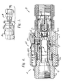
- Figure 1 shows a mating pair of body and stem coupling members or assemblies A and B respectively.
- the coupling components are in a disconnected relationship but in alignment as they are about to be connected upon movement axially towards one another.
- the body assembly A includes a main body assembly C which has a substantially annular configuration and carries a body valve element D axially therein.
- a slide valve assembly E is carried within the annular chamber and mounted for axial sliding movement between an axially outer position (as shown in Figure 3) wherein it is sealingly engaged with the valve element D to a leftward position wherein flow can take place through the assembly.
- the slide sleeve assembly E is normally continually biased to the right as illustrated in Figure 3 by a compression type coil spring 12.
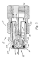
- the stem assembly B includes an elongated hollow stem body assembly F which houses a poppet valve element G that is carried and guided by a guide assembly H.
- An elongated compression type coil spring 14 functions to maintain the poppet element G continually biased to the left hand closed position illustrated in Figure 5. In this position, the poppet element G cooperates with the seal assembly 16 to close the passage through the stem body assembly F.
- the body C of body assembly A comprises a first body component 16 which has a reduced diameter right hand end portion 18 and a central stepped diameter passage 20 formed therethrough.
- the left hand end of passage 20 is provided with suitable threads or other connecting means to allow the body assembly A to be connected to associated fluid lines.
- Joined to body component 16 is an outer sleeve like body component 22.
- the body component 22 is releasably joined to body component 16 by suitable threads 24.
- a relatively short cylindrical abutment sleeve or housing member 26 having a radially inwardly extending flange 28 is located radially outwardly of the left hand end (as viewed in Figure 2) of the body component 22. It is held and clamped in position by having its inwardly extending end flange 28 captured between the threadedly connected body components 16 and 22.
- Body valve assembly D Fixedly mounted within the reduced diameter end portion of body component 16 is the body valve assembly D.
- Body valve assembly D includes an elongated rigid body or bolt portion 30 which terminates in a substantially cylindrical valve section 32. As best shown in Figure 4, the body section 30 is flat and of a width "W" to be closely received in the reduced diameter portion of passage 20. This results in a pair of flow passages 33 on opposite sides of the bolt portion 30.
- the body valve D is mechanically joined to body component 16 by three axially displaced equal crimps 34.
- the exterior of the bolt portion 30 of the body valve D is provided with three equally spaced grooves or slots 36 on each lateral edge thereof.
- the body 30 includes radially outwardly extending shoulder or flange portions 38 which are located at a diameter greater than the internal diameter of the reduced diameter section of passageway 20. Additionally, this assists in locating the bolt portion 30 for the crimping operation, the radial dimension of the sections 38 is greater than the minimum internal diameter of the slide sleeve assembly E. As will subsequently be apparent, this acts to prevent the body valve from being expelled from the assembly if failure occurs.
- body component 22 preferably has a substantially elliptical or oval exterior shape in planes perpendicular to the longitudinal axis. It is positioned with the major axis of the ellipse to extend coextensive with centerline C1. The minor axis is located on centerline axis C2.
- the center of element 22 has a cylindrical bore 40 which cooperates with the reduced diameter section of component 16 to define an outwardly open annular chamber 42.
- the assembly E comprises a substantially cylindrical slide sleeve member 44 which has a stepped internal passageway including a first section 46 which is sized to be closely received on the exterior of the reduced diameter section of body section 16.
- a reduced diameter section 48 is sized so as to closely and sealingly receive the cylindrical end section 32 of the body valve D in the manner illustrated in Figure 3.
- the exterior of sleeve 44 has a radially outward extending flange 50 which is sized to be received closely within the major internal diameter of body section 22.
- Slide sleeve member 44 is continually biased to the right hand position illustrated in Figure 3 by the previously mentioned compression spring 12.
- Movement to the right is limited by engagement of the flange 50 with the internal shoulder 52 formed in body section 22.
- the arrangement of the flange 50 and internal shoulder 52 which limits movement of the sleeve member 44 produces both structural and functional advantages. More particularly, because the body bolt 30 is not required to restrain the sleeve member 44, the bolt can be small and of lesser cross-section thus allowing greater flow area and reduced flow resistance. In addition, with the subject design axial pressure thrust is contained and resisted by the body section 22 in both the coupled and uncoupled conditions. Because of this, no additional material or strength considerations are required.
- a suitable O-ring seal 54 and a backup ring 56 are carried within an external circumferential groove formed on the right hand end of the reduced diameter portion 18 of body component 16. This provides a fluid tight seal between the sliding surfaces of the sleeve member 44 and the reduced diameter section of body member 16.
- FIG. 3A Sealing between the right hand and/or cylindrical portion 32 of the body valve D and the interior reduced diameter section 48 of the slide element 44 is accomplished by an improved seal assembly best illustrated in Figure 3A.
- the cylindrical section 32 of the body valve D is provided with a circumferentially extending contoured groove 58 including a relatively shallow axially outward groove section 60 and a significantly deeper groove section 62.
- This arrangement allows use of a continuous PTFE ring 64 to function as a backup ring for the associated O-ring seal element 66.
- the arrangement of the contoured groove 58 is such that the effective outer diameters of the backup ring and O-ring are the same but they can have significantly different internal diameters.
- the wiper can assembly I includes a substantially cylindrical thin metal can like element 70 having a cylindrical configuration and a radially inwardly extending forward flange or end wall 72.
- the main body portion of the can element 70 has an opened internal diameter sized so as to allow it to be closely and slidably received on the outer surface of the intermediate portion of sleeve member 44.
- the inner diameter of the flange end section 72 is, however, only slightly larger than the outer diameter of the reduced diameter outer end portion of the sleeve member 44.
- the relationship of the end face 72 to the body member 22 and the sleeve member 44 is best illustrated in Figure 2.
- the end wall or flange 72 acts to substantially completely fill or, in effect, close the outer end of the body member A when the coupling is in a disconnected condition as shown in Figures 2 and 3. This prevents dirt and foreign materials from entering into the internal mechanism of the coupling.
- a circumferentially continuous resilient wiper member 74 is carried by the flange section 72 and is sized so that its inner diameter is slightly smaller than the outer diameter of the end section of member 44. This produces a movable seal and wiping element as the can element 70 is axially moved relative to the sleeve member 44.
- the resilient wiper member 74 is firmly maintained in position adjacent the flange 72 by a metal backup ring 76 which is maintained in engagement against the rear side of the wiper ring 74 by a compression spring 78.
- the compression spring 78 has a substantially conical shape and acts between a shoulder on sleeve member 44 and the backup ring 76. Additionally, the compression spring 78 acts to maintain the wiper can element 70 continually biased towards the open outer end of the body assembly A.
- the limit of outer movement of the wiper can assembly I is defined by the slide hook assembly J.
- the subject device uses two slide hook members 80 located on diametrically opposite sides of the sleeve member 44.
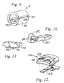
- the hook members 80 have the overall configuration best seen in Figure 10 and include an inwardly extending hook portion 82 which is received in a circumferential groove 84 formed in sleeve member 44 at the general location illustrated.
- the hook members 80 are maintained in engagement with the groove 84 by their relationship with the cylindrical wiper can element 70.
- the wiper can element 70 includes elongated slots 86 through which the hook portions 82 extend.
- each hook portion 82 is provided with inwardly extending side grooves 88 that receive the sides of the slot 86. As illustrated in Figure 9, entry of the hook portion 82 during assembly can take place through a slightly widened part 87 in the slot 86. The relationship thus far described allows the wiper can element to move axially relative to the slide hook while permitting the hook member 80 to maintain positive engagement with the groove 84 in the sleeve member 44. Additionally, as best illustrated in Figures 2 and 4, the slide hook members 80 and the wiper can element 70 are axially guided by elongated slots 90 formed radially outwardly from the interior surface of bore 40 of body member 22. As illustrated, the grooves are located in diametrically opposite sides and are sized so as to closely receive the sides of the respective slide hook members 80. This maintains the slide hook members oriented in the position shown and prevents rotation of the wiper can assembly I.
- the assembly further includes the locking dog detent assembly K which functions to maintain the body assembly A and the stem assembly in the connected relationship shown in Figure 6 until it is desired to release the locking dogs.
- the locking dog detent assembly K which functions to maintain the body assembly A and the stem assembly in the connected relationship shown in Figure 6 until it is desired to release the locking dogs.
- the locking dog elements 94 have the general configuration best shown in Figure 11.
- the locking dog elements 94 have opposed substantially parallel side walls 96 and 98 (see Figure 3) which are sized so as to be closely and slidably received in a transversely extending slot 100 formed through body component 22.
- the slots 100 guide the radial movement of the dog elements 94 and constrain them against undesired axial movement.
- the locking dog elements are constrained against circumferential movement by having a lower rectangular end section 102 which extends through a rectangular opening connecting between slot 100 and the annular chamber within body component 22. This rectangular opening is provided by a longitudinally extending slot 104 formed from the inner wall 40 of component 22.
- control sleeve 110 which is mounted for axial sliding movement between an outermost coupled position illustrated in Figure 6 and an innermost uncoupled position illustrated in Figure 3.
- control sleeve 110 is formed from powdered metal and has the exterior configuration best seen in Figures 1 through 4.
- sleeve 110 has an internal open configuration to closely receive the exterior of body component 22.
- the exterior configuration of control sleeve 110 preferably has an oval or substantially elliptical shape with the major axis of the ellipse extending in the direction of centerline C2.
- the oval or elliptical exterior surfaces of the body component 22 and the oval inner opening of control sleeve 110 maintain the desired circumferential orientation between these components and, further, allow the body end sleeve to have maximum strength in those areas and directions where such strength is required.
- the control sleeve 110 includes a longitudinally extending groove 112 that is positioned to engage the lateral ends of the dog elements 94.
- the groove is contoured as best shown in Figure 3.
- the groove 112 has a maximum radial depth at the outer end to permit the individual dog elements 94 to assume their radially outermost position and permit the sleeve member 44 to assume the right hand closed position.
- the sleeve member 44 and the wiper can element 70 are in their maximum left hand position and the dog elements 9 have then moved radially inwardly into engaged position with the stem portion 152 of stem assembly B as illustrated.
- control sleeve 110 In order to allow the control sleeve 110 to properly perform its function, it is maintained under a continual bias to the right towards the position shown in Figure 6. Movement to the right is limited by engagement of the axially inner end of groove 112 with the radially outer edge of the associated dog elements 94. Biasing of the control sleeve 110 is accomplished by a compression spring 116 which acts between the end wall 28 of sleeve 26 and the end of the sleeve 110.
- the subject device includes a lock button assembly 120 which prevents inadvertent release movement of the sleeve 110 by requiring a separate radial inward movement of the lock button assembly 120 before it is possible to slide the control sleeve 110 against the bias of spring 116.
- the lock button assembly 120 includes a stamped metal lock button element 122 which is suitably mounted in an opening 124 formed through the control sleeve 110. This allows the outer surface of the button element 122 to be exposed for manual access.
- the button element 122 is maintained in its operating position by a leaf spring element 126 (see Figures 3 and 12) which has an end portion 128 suitably received in a recess formed in the interior of the control sleeve 110.
- the upper end or left hand portion of the leaf spring 126 is suitably received under the button element 122 and maintains it biased to the position shown in Figure 6.
- the pair of stop elements 130 extend upwardly from the surface of button element 122 to a position for engagement with the end 26A of sleeve 26. As shown in Figure 6, this prevents axial movement of operating sleeve 110 unless the button 122 is pivoted inwardly to a position wherein the elements 130 can pass under the sleeve 26.
- Figure 3 illustrates the button element 122 in this depressed position.
- the button element 122 is arranged such that, considering the positioning of the spring 126 and the shape of the button element 122, rotation of this button during the release operation takes place about the inner corner of opening 124. Since the rotation is about an axis that is further inward than the outside diameter of the control sleeve release is less likely to be a problem with this particular design.
- the stem assembly B comprises a main stem body assembly F which is a two part assembly comprises a main body component 150 and a threadedly connected stem component 152.
- the main body component 150 is substantially cylindrical with external wrench flats as shown in Figure 1.
- a first end 154 is suitably provided with internal threads to permit connection of the stem assembly to associated piping, tubing or the like.
- the second end 156 is threadedly connected to the stem component 152 and sealing between the components 150 and 152 is accomplished by a seal ring 158 captured between suitable internal shoulders.
- the stem component 152 is provided with a stepped diameter internal passageway 160 which terminates in a reduced diameter outer end which receives the substantially cylindrical poppet valve element G.
- a suitable O-ring 162 and an associated backup ring 164 are received in a groove 166 formed about the inner end of stem component 152.
- the O-ring 162 is sized so as to be closely received about the outer surface of the poppet element G to provide a fluid tight seal relative thereto. Outward movement of the poppet element is limited by cooperating shoulder 170 and 172 formed on the poppet element and the passageway 160 respectively.
- the poppet element G is maintained continually under a bias towards the position illustrated in Figure 5 by the previously mentioned spring 14 and the guide assembly H.
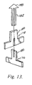
- the guide assembly H is best shown in Figure 13 and comprises a first support member 176 which is comprised of two substantially T-shaped components 177, 178 which are interfitted as shown to provide a support base and upwardly extending guide stem 180.
- the support base and the guide stem have a substantially X-shaped configuration in planes transverse to their longitudinal axis.
- a movable guide member 182 is provided with a central elongated slot 184 to provide a pair of legs 186 which can extend on diametrically opposite sides of the guide stem 180 for guide movement relative thereto.
- a pointed outer end 188 on the member 182 is arranged to engage within an internal bore 190 formed in the poppet element G.
- This assembly guides the poppet element G during reciprocatory movement from the position shown in Figure 5 to the open position shown in Figure 6.
- the exterior surface of the stem component 152 is provided with a pair of axially spaced circumferentially extending grooves 200 and 202.
- the axially outer groove 200 is arranged to provide a point of engagement for the slide hook members 80.
- the hook member 80 has an inwardly extending hook end portion 204 which is adapted to be received within the groove 200 when the components are in the coupled position of Figures 6 and 7.
- the groove 202 is arranged to receive the locking dog elements 94 and maintain the components in the coupled position shown in Figure 6.
- the contour of the groove 202 is such as to provide a camming action against the suitable inclined inner end of the locking dog elements 94.
- the design of the slide hook members 80 and their relationship to the stem coupling assembly B is such that the design can readily be used to provide a keyed arrangement between various different coupling members.
- matched, coded coupling sets can be provided merely by changing the stem component 152 on the stem coupling assembly and the pairs of hook elements 80.
Landscapes
- Engineering & Computer Science (AREA)
- General Engineering & Computer Science (AREA)
- Mechanical Engineering (AREA)
- Quick-Acting Or Multi-Walled Pipe Joints (AREA)
Claims (13)
- Kupplungsteil für eine Schnellverbindungs- und schnellösekupplung mit den folgenden Merkmalen: ein längliches, hohles Gehäuse (A); ein Ventil (D), das intern im genannten hohen Gehäuse (A) getragen ist und mit diesem eine Ringkammer festlegt, die ein axial offenes ende zur Aufnahme einer passenden Kupplungskomponente (B) aufweist; eine Schiebehülse (E), die vom genannten Gehäuse (A) für die axiale Bewegung in der genannten Ringkammer zwischen einer geschlossenen Lage, in der sie in das genannte Ventil (D) eingreift, und einer offenen Lage, die gegenüber dem genannten Ventil axial versetzt ist, getragen ist; und ein im wesentlichen zylindrisches Wischerteil (I), das für die Verschiebebewegung an der genannten Schiebehülse (E) angebracht ist und eine Endfläche aufweist, die im wesentlichen das offene ende der genannten Ringkammer ausfüllt; gekennzeichnet durch mindestens einen Schließhaken (J) zum Bewegen der genannten Schiebehülse (E) in die genannte geschlossene Lage, wobei der genannte Schließhaken (J) einen Körper aufweist, der radial außerhalb des zylindrischen Wischerteils (I) angeordnet ist, sowie einen Fingerabschnitt (82), der sich radial einwärts durch eine Öffnung im genannten zylindrischen Wischerteil (I) bis in Antriebseingriff mit der genannten Schiebehülse (E) erstreckt.
- Kupplungsteil nach Anspruch 1, worin der Haken (J) in das genannte zylindrische Wischerteil (I) eingreift, um die radiale Trennung des genannten Hakens und des genannten Wischerteils zu vermeiden, während eine axiale Relativbewegung gestattet ist.
- Kupplungsteil nach Anspruch 1 oder 2, mit einer Vorspanneinrichtung (12, 78), um die genannte Schiebehülse (E) und das genannte Wischerteil (I) axial zum genannten offenen Ende der genannten Ringkammer hin vorbelastet zu halten.
- Kupplungsteil nach Anspruch 1, 2 oder 3, worin das genannte hohle Gehäuse (A) eine Nuteinrichtung (90) zum axialen Führen des genannten Schließhakens (J) und des genannten Wischerteiles (I) aufweist.
- Kupplungsteil nach irgendeinem der Ansprüche 1 bis 4, worin der genannte Haken (J) ein äußeres freies Ende umfaßt, das einen Axialabstand zum genannten Finger (82) aufweist und einen Abschnitt (204) hat, der dazu eingerichtet ist, in eine dazu passende Kupplungskomponente einzugreifen.
- Kupplungsteil nach irgendeinem der Ansprüche 1 bis 5, worin das genannte zylindrische Wischerteil (I) eine federnde Dichtung (74) aufweist, die sich im wesentlichen radial von der genannten Endfläche nach innen bis in Dichtungseingriff mit der genannten Schiebehülse (E) erstreckt.
- Kupplungsteil nach irgendeinem der Ansprüche 1 bis 6, worin eine Anzahl der genannten Schiebe-Schließhaken (J) an mit Umfangsabstand angeordneten Stellen rund um die genannte Schiebehülse (E) angeordnet ist.
- Kupplungsteil nach irgendeinem der Ansprüche 1 bis 7, worin radial bewegliche Sperrnasen (K) vom genannten Gehäuse (A) radial außerhalb der genannten Ringkammer getragen sind, um wahlweise das Kupplungsteil mit einer passenden Kupplungskomponente zu verbinden; und worin eine Steuerhülse (110) das genannte Gehäuse (A) umgibt, um die Radialbewegung der genannten Sperrnasen (K) zu steuern.
- Kupplungsteil nach Anspruch 8, worin das genannte zylindrische Wischerteil (I) so angeordnet ist, daß es die radial einwärts gerichtete Bewegung der genannten Sperrnasen (K) begrenzt, wenn sich das Wischerteil in seiner axial äußersten Lage befindet.
- Kupplungsteil nach Anspruch 8 oder 9, worin das genannte Gehäuse (A) einen im wesentlichen elliptischen Querschnitt in Ebenen senkrecht zu seiner Längsachse aufweist, und die Sperrnasen (K) gezwungen sind, sich radial im wesentlichen längs der Nebenachse des genannten elliptischen Querschnitts zu bewegen.
- Kupplungsteil nach Anspruch 8, 9 oder 10, worin die genannte Steuerhülse (110) einen im wesentlichen elliptischen äußeren Querschnitt in Ebenen senkrecht zur Längsachse der Kupplung aufweist und durch die genannten Sperrnasen (K) hindurchläuft.
- Kupplungsteil nach Anspruch 10 und 11, worin die Hauptachse des elliptischen Querschnitts der genannten Steuerhülse (110) im wesentlichen senkrecht steht zur Hauptachse des elliptischen Querschnitts des Gehäuses (A).
- Kupplungsteil nach irgendeinem vorangehenden Anspruch, worin die genannte Schiebehülse (E) eine im wesentlichen zylindrische Ausbildung aufweist und in Umfangsrichtung des genannten Ventils (D) angebracht ist.
Applications Claiming Priority (2)
| Application Number | Priority Date | Filing Date | Title |
|---|---|---|---|
| US369070 | 1970-01-19 | ||
| US07/369,070 US4982761A (en) | 1989-06-20 | 1989-06-20 | Valved quick connect/disconnect coupling |
Publications (3)
| Publication Number | Publication Date |
|---|---|
| EP0404495A2 EP0404495A2 (de) | 1990-12-27 |
| EP0404495A3 EP0404495A3 (de) | 1991-04-24 |
| EP0404495B1 true EP0404495B1 (de) | 1993-09-22 |
Family
ID=23453982
Family Applications (1)
| Application Number | Title | Priority Date | Filing Date |
|---|---|---|---|
| EP19900306642 Expired - Lifetime EP0404495B1 (de) | 1989-06-20 | 1990-06-19 | Schnellvervindungs- und Schnellöse-Kupplung |
Country Status (6)
| Country | Link |
|---|---|
| US (1) | US4982761A (de) |
| EP (1) | EP0404495B1 (de) |
| JP (1) | JPH0396790A (de) |
| CA (1) | CA2019227A1 (de) |
| DE (1) | DE69003467T2 (de) |
| HK (1) | HK122696A (de) |
Families Citing this family (32)
| Publication number | Priority date | Publication date | Assignee | Title |
|---|---|---|---|---|
| US5123447A (en) * | 1991-03-11 | 1992-06-23 | Calvin John H | Quick disconnect coupling |
| US5123446A (en) * | 1991-07-05 | 1992-06-23 | Aeroquip Corporation | Dual seal coupling |
| SE9203040L (sv) * | 1992-10-16 | 1994-04-11 | Bjoern Engdahl | Slangkoppling för tryckluft med don för tryckavlastning vid isärkoppling |
| JPH06288405A (ja) * | 1993-03-31 | 1994-10-11 | Japan Aircraft Mfg Co Ltd | 接続機構 |
| AU4854596A (en) * | 1995-01-06 | 1996-07-24 | Colder Products Company | Low spill high flow quick coupling valve assembly |
| US6082401A (en) * | 1995-01-06 | 2000-07-04 | Colder Products Company | Low spill high flow quick coupling valve assembly |
| TW327672B (en) * | 1995-10-05 | 1998-03-01 | Babcock & Wilcox Co | Field serviceable fill tube for use on heat pipes |
| SE506405C2 (sv) * | 1996-03-22 | 1997-12-15 | Nyberg Bo Erik | Snabbkoppling med tryckavlastning för säkert lösgörande |
| US6161578A (en) * | 1996-10-09 | 2000-12-19 | Colder Products Company | Low spill high flow quick coupling valve assembly |
| FR2786849B1 (fr) * | 1998-12-03 | 2001-01-26 | Staubli Sa Ets | Raccord rapide de securite pour la jonction amovible de canalisations |
| US6460899B1 (en) * | 1999-02-11 | 2002-10-08 | Airmo, Inc. | Disconnect coupling |
| JP2002102105A (ja) * | 2000-10-02 | 2002-04-09 | 津杰 ▲リュウ▼ | 心棒無しホルダー |
| FR2822920B1 (fr) * | 2001-04-03 | 2003-10-31 | Staubli Sa Ets | Raccord rapide pour la jonction amovible de deux canalisations, et son utilisation |
| ITMI20011105A1 (it) * | 2001-05-25 | 2002-11-25 | Faster Srl | Innesto rapido a faccia piana, con mezzi per evitare una fuoriuscita di fluido idraulico durante la fase di accoppiamento o di disaccoppiame |
| US7712794B2 (en) * | 2003-05-02 | 2010-05-11 | Asia Pacific Fuel Cell Technologies, Ltd. | Rapid coupling device for hydrogen storage canister |
| SE529075C2 (sv) * | 2005-05-23 | 2007-04-24 | Bjoern Engdahl | Kombinerad spärr- och låskropp |
| TW200717906A (en) * | 2005-07-18 | 2007-05-01 | Bic Soc | Fuel supply with improved connecting valve |
| FR2895058B1 (fr) * | 2005-12-20 | 2008-03-14 | Parker Hannifin France Sas Soc | Coupleur rigide pour conduites de fluide sous pression, permettant la connexion de ces conduites alors que du fluide sous pression subsiste dans l'une d'elles |
| EP2024673B1 (de) * | 2006-05-15 | 2013-05-15 | Colder Products Company | Aseptische kupplungsvorrichtungen |
| WO2009062875A1 (en) * | 2007-11-12 | 2009-05-22 | Nestec S.A. | Fitment for connecting a container to a dispensing appliance |
| US8191575B2 (en) * | 2008-04-11 | 2012-06-05 | International Business Machines Corporation | Double poppet quick connect |
| EP2425160A1 (de) * | 2009-05-01 | 2012-03-07 | Swagelok Company | Dichtung mit dichtungsstützhalterung |
| WO2011010939A1 (en) * | 2009-07-20 | 2011-01-27 | Illinois Tool Works, Inc. | Fluid dispensing assembly |
| ES2455592T3 (es) * | 2011-04-14 | 2014-04-16 | Cejn Ab | Acoplamiento para aire comprimido |
| US10941892B2 (en) | 2017-02-17 | 2021-03-09 | Hewlett Packard Enterprise Development Lp | Valved connector |
| US10814533B2 (en) | 2017-11-30 | 2020-10-27 | The Boeing Company | Systems and methods for applying vacuum pressure to composite parts |
| US11608919B2 (en) * | 2018-02-27 | 2023-03-21 | Intel Corporation | Universal quick disconnect |
| GB2575620A (en) * | 2018-04-27 | 2020-01-22 | John Guest International Ltd | A collet for locking a tube in a coupling body |
| US12203579B2 (en) | 2020-11-16 | 2025-01-21 | Colder Products Company | Fluid handling couplings |
| WO2022103569A1 (en) * | 2020-11-16 | 2022-05-19 | Colder Products Company | Fluid handling couplings |
| CN115126545B (zh) * | 2021-03-26 | 2025-08-01 | 中国航发商用航空发动机有限责任公司 | 航空发动机 |
| CN119712986B (zh) * | 2025-01-22 | 2025-10-10 | 江南造船(集团)有限责任公司 | 一种船岸连接保护装置及使用方法 |
Family Cites Families (26)
| Publication number | Priority date | Publication date | Assignee | Title |
|---|---|---|---|---|
| US3123099A (en) * | 1964-03-03 | High pressure fluid coupling | ||
| US2208286A (en) * | 1937-01-26 | 1940-07-16 | Berger Julius | Pipe coupling |
| US2425500A (en) * | 1943-07-07 | 1947-08-12 | Wiggins Irene Lane | Valved coupling |
| US2381962A (en) * | 1943-12-09 | 1945-08-14 | Wheaton Brass Works | Hose coupling |
| US2413978A (en) * | 1945-05-08 | 1947-01-07 | Wheaton Brass Works | Quick hose coupling |
| US2727759A (en) * | 1951-10-27 | 1955-12-20 | Hughes Tool Co | Valved couplers for fluid-conducting conduits |
| BE542454A (de) * | 1954-11-08 | 1900-01-01 | ||
| US2951713A (en) * | 1956-03-12 | 1960-09-06 | Hoffstrom Bo Nilsson | Couplings |
| US2888278A (en) * | 1956-06-18 | 1959-05-26 | E B Wiggins Oil Tool Company I | Coupling with automatically actuated cam sleeve |
| US2952482A (en) * | 1957-02-04 | 1960-09-13 | E B Wiggins Oil Tool Company I | Coupling with automatically actuated cam sleeve |
| US3039794A (en) * | 1958-07-14 | 1962-06-19 | On Mark Couplings Inc | Quick disconnect coupling for high pressure fluids |
| US3028179A (en) * | 1958-12-29 | 1962-04-03 | Weatherhead Co | Self-sealing locking coupling with manipulator and pivoted latch means |
| US3113588A (en) * | 1960-05-09 | 1963-12-10 | On Mark Couplings Inc | Fluid conduit coupling |
| US3097867A (en) * | 1961-04-13 | 1963-07-16 | Snap Tite Inc | Coupling |
| US3234965A (en) * | 1962-09-17 | 1966-02-15 | E B Wiggins Oil Tool Company I | Coupling assembly |
| US3367366A (en) * | 1965-10-11 | 1968-02-06 | Universal Oil Prod Co | Disconnect with minimum inclusion |
| US3613726A (en) * | 1965-12-02 | 1971-10-19 | Purolator Products Inc | Balanced pressure coupling |
| US3435848A (en) * | 1967-03-20 | 1969-04-01 | James R Johnston | Fluid line coupler |
| DE2138103C3 (de) * | 1971-07-30 | 1980-04-30 | Otto Dipl.-Ing. 5828 Ennepetal Busselmeier | Schnellkupplung für Flüssigkeitsund Gasleitungen |
| US4086939A (en) * | 1976-09-03 | 1978-05-02 | Snap-Tite, Inc. | Coupling assembly |
| SE428721B (sv) * | 1980-01-30 | 1983-07-18 | Ronny Ekman | Anordning vid kopplingsdel |
| US4685490A (en) * | 1983-01-19 | 1987-08-11 | Swagelok Company | Coupling |
| US4637432A (en) * | 1983-01-19 | 1987-01-20 | Swagelok Company | Coupling |
| US4596272A (en) * | 1984-02-27 | 1986-06-24 | Swagelok Company | Coupling |
| GB2166501B (en) * | 1984-11-01 | 1988-06-15 | Sterling Hydraulics Limited | Sealing member |
| US4693497A (en) * | 1986-06-19 | 1987-09-15 | Cameron Iron Works, Inc. | Collet connector |
-
1989
- 1989-06-20 US US07/369,070 patent/US4982761A/en not_active Expired - Fee Related
-
1990
- 1990-06-18 CA CA 2019227 patent/CA2019227A1/en not_active Abandoned
- 1990-06-19 EP EP19900306642 patent/EP0404495B1/de not_active Expired - Lifetime
- 1990-06-19 DE DE90306642T patent/DE69003467T2/de not_active Expired - Fee Related
- 1990-06-20 JP JP2162528A patent/JPH0396790A/ja active Pending
-
1996
- 1996-07-11 HK HK122696A patent/HK122696A/en not_active IP Right Cessation
Also Published As
| Publication number | Publication date |
|---|---|
| EP0404495A2 (de) | 1990-12-27 |
| US4982761A (en) | 1991-01-08 |
| EP0404495A3 (de) | 1991-04-24 |
| HK122696A (en) | 1996-07-19 |
| JPH0396790A (ja) | 1991-04-22 |
| DE69003467D1 (de) | 1993-10-28 |
| DE69003467T2 (de) | 1994-01-20 |
| CA2019227A1 (en) | 1990-12-20 |
Similar Documents
| Publication | Publication Date | Title |
|---|---|---|
| EP0404495B1 (de) | Schnellvervindungs- und Schnellöse-Kupplung | |
| US4485845A (en) | Quick disconnect coupling | |
| EP0238201A2 (de) | Kegelsitzventil-Montage | |
| CA1173074A (en) | Quick connect coupling | |
| EP0753120B1 (de) | Tiefziehbare schnellkupplung | |
| AU733118B2 (en) | Low spill quick coupling | |
| US6257278B1 (en) | High pressure fluidline connector | |
| US6637779B2 (en) | Fluid quick connector with grooved endform | |
| US4685490A (en) | Coupling | |
| US4637432A (en) | Coupling | |
| US7314209B2 (en) | Stub out fluid quick connector with shut off valve interface | |
| EP1348090B1 (de) | Schnellverbinder mit rückschlagventil | |
| US7121592B2 (en) | Fluid quick connect with adjustable flow control valve | |
| AU697154B2 (en) | Low spill female coupling | |
| US6802491B1 (en) | Fluid shut off valve cartridge with quick connection | |
| GB2293221A (en) | Hydraulic coupling with axial preloading of seal | |
| EP1479962A1 (de) | Schnellverbindungsvorrichtung |
Legal Events
| Date | Code | Title | Description |
|---|---|---|---|
| PUAI | Public reference made under article 153(3) epc to a published international application that has entered the european phase |
Free format text: ORIGINAL CODE: 0009012 |
|
| AK | Designated contracting states |
Kind code of ref document: A2 Designated state(s): BE DE FR GB IT NL |
|
| PUAL | Search report despatched |
Free format text: ORIGINAL CODE: 0009013 |
|
| RHK1 | Main classification (correction) |
Ipc: F16L 37/28 |
|
| AK | Designated contracting states |
Kind code of ref document: A3 Designated state(s): BE DE FR GB IT NL |
|
| 17P | Request for examination filed |
Effective date: 19910926 |
|
| 17Q | First examination report despatched |
Effective date: 19920724 |
|
| GRAA | (expected) grant |
Free format text: ORIGINAL CODE: 0009210 |
|
| AK | Designated contracting states |
Kind code of ref document: B1 Designated state(s): BE DE FR GB IT NL |
|
| REF | Corresponds to: |
Ref document number: 69003467 Country of ref document: DE Date of ref document: 19931028 |
|
| ITF | It: translation for a ep patent filed | ||
| ET | Fr: translation filed | ||
| PLBE | No opposition filed within time limit |
Free format text: ORIGINAL CODE: 0009261 |
|
| STAA | Information on the status of an ep patent application or granted ep patent |
Free format text: STATUS: NO OPPOSITION FILED WITHIN TIME LIMIT |
|
| 26N | No opposition filed | ||
| PGFP | Annual fee paid to national office [announced via postgrant information from national office to epo] |
Ref country code: NL Payment date: 19960328 Year of fee payment: 7 |
|
| PGFP | Annual fee paid to national office [announced via postgrant information from national office to epo] |
Ref country code: GB Payment date: 19960509 Year of fee payment: 7 |
|
| PGFP | Annual fee paid to national office [announced via postgrant information from national office to epo] |
Ref country code: FR Payment date: 19960607 Year of fee payment: 7 |
|
| PGFP | Annual fee paid to national office [announced via postgrant information from national office to epo] |
Ref country code: DE Payment date: 19960625 Year of fee payment: 7 |
|
| PGFP | Annual fee paid to national office [announced via postgrant information from national office to epo] |
Ref country code: BE Payment date: 19960703 Year of fee payment: 7 |
|
| PG25 | Lapsed in a contracting state [announced via postgrant information from national office to epo] |
Ref country code: GB Free format text: LAPSE BECAUSE OF NON-PAYMENT OF DUE FEES Effective date: 19970619 |
|
| PG25 | Lapsed in a contracting state [announced via postgrant information from national office to epo] |
Ref country code: BE Effective date: 19970630 |
|
| BERE | Be: lapsed |
Owner name: SWAGELOK QUICK-CONNECT CO. Effective date: 19970630 |
|
| PG25 | Lapsed in a contracting state [announced via postgrant information from national office to epo] |
Ref country code: NL Effective date: 19980101 |
|
| GBPC | Gb: european patent ceased through non-payment of renewal fee |
Effective date: 19970619 |
|
| PG25 | Lapsed in a contracting state [announced via postgrant information from national office to epo] |
Ref country code: FR Free format text: LAPSE BECAUSE OF NON-PAYMENT OF DUE FEES Effective date: 19980227 |
|
| NLV4 | Nl: lapsed or anulled due to non-payment of the annual fee |
Effective date: 19980101 |
|
| PG25 | Lapsed in a contracting state [announced via postgrant information from national office to epo] |
Ref country code: DE Free format text: LAPSE BECAUSE OF NON-PAYMENT OF DUE FEES Effective date: 19980303 |
|
| REG | Reference to a national code |
Ref country code: FR Ref legal event code: ST |
|
| REG | Reference to a national code |
Ref country code: FR Ref legal event code: ST |
|
| PG25 | Lapsed in a contracting state [announced via postgrant information from national office to epo] |
Ref country code: IT Free format text: LAPSE BECAUSE OF NON-PAYMENT OF DUE FEES Effective date: 20050619 |