EP0403940B1 - Hochfeste Befestigungsmittel aus faserverstärkten Polymeren mit Gewinden, zum Beispiel Schraubenmutter und -bolzen - Google Patents
Hochfeste Befestigungsmittel aus faserverstärkten Polymeren mit Gewinden, zum Beispiel Schraubenmutter und -bolzen Download PDFInfo
- Publication number
- EP0403940B1 EP0403940B1 EP90111148A EP90111148A EP0403940B1 EP 0403940 B1 EP0403940 B1 EP 0403940B1 EP 90111148 A EP90111148 A EP 90111148A EP 90111148 A EP90111148 A EP 90111148A EP 0403940 B1 EP0403940 B1 EP 0403940B1
- Authority
- EP
- European Patent Office
- Prior art keywords
- die
- fastener
- contours
- side walls
- thread
- Prior art date
- Legal status (The legal status is an assumption and is not a legal conclusion. Google has not performed a legal analysis and makes no representation as to the accuracy of the status listed.)
- Expired - Lifetime
Links
- 239000000835 fiber Substances 0.000 title claims description 8
- 238000000034 method Methods 0.000 claims description 26
- 229920005989 resin Polymers 0.000 claims description 25
- 239000011347 resin Substances 0.000 claims description 25
- 239000000463 material Substances 0.000 claims description 13
- 238000000465 moulding Methods 0.000 claims description 11
- 230000001427 coherent effect Effects 0.000 claims description 10
- 230000003014 reinforcing effect Effects 0.000 claims description 10
- 238000005304 joining Methods 0.000 claims description 5
- 238000002347 injection Methods 0.000 claims description 4
- 239000007924 injection Substances 0.000 claims description 4
- 238000009736 wetting Methods 0.000 claims description 3
- 239000002952 polymeric resin Substances 0.000 claims description 2
- 238000003825 pressing Methods 0.000 claims description 2
- 229920003002 synthetic resin Polymers 0.000 claims description 2
- 229920001187 thermosetting polymer Polymers 0.000 claims description 2
- 239000011435 rock Substances 0.000 description 11
- 229920002430 Fibre-reinforced plastic Polymers 0.000 description 6
- 239000004568 cement Substances 0.000 description 6
- 239000011151 fibre-reinforced plastic Substances 0.000 description 6
- 239000011152 fibreglass Substances 0.000 description 6
- 238000004519 manufacturing process Methods 0.000 description 6
- 239000011295 pitch Substances 0.000 description 6
- 230000002787 reinforcement Effects 0.000 description 6
- 230000000694 effects Effects 0.000 description 5
- 238000005065 mining Methods 0.000 description 5
- 239000004412 Bulk moulding compound Substances 0.000 description 4
- 229910001209 Low-carbon steel Inorganic materials 0.000 description 4
- 239000003677 Sheet moulding compound Substances 0.000 description 4
- 229910052751 metal Inorganic materials 0.000 description 4
- 239000002184 metal Substances 0.000 description 4
- 229910000831 Steel Inorganic materials 0.000 description 3
- 238000005520 cutting process Methods 0.000 description 3
- 239000012530 fluid Substances 0.000 description 3
- 239000011440 grout Substances 0.000 description 3
- 239000010959 steel Substances 0.000 description 3
- RTAQQCXQSZGOHL-UHFFFAOYSA-N Titanium Chemical compound [Ti] RTAQQCXQSZGOHL-UHFFFAOYSA-N 0.000 description 2
- 229910003460 diamond Inorganic materials 0.000 description 2
- 239000010432 diamond Substances 0.000 description 2
- 239000000945 filler Substances 0.000 description 2
- 238000009434 installation Methods 0.000 description 2
- 150000002739 metals Chemical class 0.000 description 2
- 239000000203 mixture Substances 0.000 description 2
- 229920000728 polyester Polymers 0.000 description 2
- 238000003892 spreading Methods 0.000 description 2
- 229910001220 stainless steel Inorganic materials 0.000 description 2
- 239000010935 stainless steel Substances 0.000 description 2
- 239000000126 substance Substances 0.000 description 2
- 239000010936 titanium Substances 0.000 description 2
- 229910052719 titanium Inorganic materials 0.000 description 2
- 229920001567 vinyl ester resin Polymers 0.000 description 2
- 241000196324 Embryophyta Species 0.000 description 1
- 239000004593 Epoxy Substances 0.000 description 1
- 240000002129 Malva sylvestris Species 0.000 description 1
- 235000006770 Malva sylvestris Nutrition 0.000 description 1
- 230000015572 biosynthetic process Effects 0.000 description 1
- 239000003054 catalyst Substances 0.000 description 1
- 235000013351 cheese Nutrition 0.000 description 1
- 230000006835 compression Effects 0.000 description 1
- 238000007906 compression Methods 0.000 description 1
- 238000010276 construction Methods 0.000 description 1
- 230000007797 corrosion Effects 0.000 description 1
- 238000005260 corrosion Methods 0.000 description 1
- 238000006073 displacement reaction Methods 0.000 description 1
- 239000011521 glass Substances 0.000 description 1
- 239000003365 glass fiber Substances 0.000 description 1
- 239000004615 ingredient Substances 0.000 description 1
- 230000014759 maintenance of location Effects 0.000 description 1
- 239000011159 matrix material Substances 0.000 description 1
- 239000000206 moulding compound Substances 0.000 description 1
- ISWSIDIOOBJBQZ-UHFFFAOYSA-N phenol group Chemical group C1(=CC=CC=C1)O ISWSIDIOOBJBQZ-UHFFFAOYSA-N 0.000 description 1
- 239000000049 pigment Substances 0.000 description 1
- 239000004033 plastic Substances 0.000 description 1
- 229920003023 plastic Polymers 0.000 description 1
- 229920001225 polyester resin Polymers 0.000 description 1
- 239000004645 polyester resin Substances 0.000 description 1
- 229920000642 polymer Polymers 0.000 description 1
- 239000002990 reinforced plastic Substances 0.000 description 1
- 235000013580 sausages Nutrition 0.000 description 1
- 239000004634 thermosetting polymer Substances 0.000 description 1
- 230000007704 transition Effects 0.000 description 1
Images




Classifications
-
- B—PERFORMING OPERATIONS; TRANSPORTING
- B29—WORKING OF PLASTICS; WORKING OF SUBSTANCES IN A PLASTIC STATE IN GENERAL
- B29C—SHAPING OR JOINING OF PLASTICS; SHAPING OF MATERIAL IN A PLASTIC STATE, NOT OTHERWISE PROVIDED FOR; AFTER-TREATMENT OF THE SHAPED PRODUCTS, e.g. REPAIRING
- B29C53/00—Shaping by bending, folding, twisting, straightening or flattening; Apparatus therefor
- B29C53/56—Winding and joining, e.g. winding spirally
- B29C53/58—Winding and joining, e.g. winding spirally helically
- B29C53/583—Winding and joining, e.g. winding spirally helically for making tubular articles with particular features
- B29C53/585—Winding and joining, e.g. winding spirally helically for making tubular articles with particular features the cross-section varying along their axis, e.g. tapered, with ribs, or threads, with socket-ends
-
- B—PERFORMING OPERATIONS; TRANSPORTING
- B29—WORKING OF PLASTICS; WORKING OF SUBSTANCES IN A PLASTIC STATE IN GENERAL
- B29C—SHAPING OR JOINING OF PLASTICS; SHAPING OF MATERIAL IN A PLASTIC STATE, NOT OTHERWISE PROVIDED FOR; AFTER-TREATMENT OF THE SHAPED PRODUCTS, e.g. REPAIRING
- B29C43/00—Compression moulding, i.e. applying external pressure to flow the moulding material; Apparatus therefor
- B29C43/02—Compression moulding, i.e. applying external pressure to flow the moulding material; Apparatus therefor of articles of definite length, i.e. discrete articles
- B29C43/021—Compression moulding, i.e. applying external pressure to flow the moulding material; Apparatus therefor of articles of definite length, i.e. discrete articles characterised by the shape of the surface
-
- B—PERFORMING OPERATIONS; TRANSPORTING
- B29—WORKING OF PLASTICS; WORKING OF SUBSTANCES IN A PLASTIC STATE IN GENERAL
- B29C—SHAPING OR JOINING OF PLASTICS; SHAPING OF MATERIAL IN A PLASTIC STATE, NOT OTHERWISE PROVIDED FOR; AFTER-TREATMENT OF THE SHAPED PRODUCTS, e.g. REPAIRING
- B29C43/00—Compression moulding, i.e. applying external pressure to flow the moulding material; Apparatus therefor
- B29C43/32—Component parts, details or accessories; Auxiliary operations
- B29C43/36—Moulds for making articles of definite length, i.e. discrete articles
- B29C43/361—Moulds for making articles of definite length, i.e. discrete articles with pressing members independently movable of the parts for opening or closing the mould, e.g. movable pistons
-
- B—PERFORMING OPERATIONS; TRANSPORTING
- B29—WORKING OF PLASTICS; WORKING OF SUBSTANCES IN A PLASTIC STATE IN GENERAL
- B29C—SHAPING OR JOINING OF PLASTICS; SHAPING OF MATERIAL IN A PLASTIC STATE, NOT OTHERWISE PROVIDED FOR; AFTER-TREATMENT OF THE SHAPED PRODUCTS, e.g. REPAIRING
- B29C70/00—Shaping composites, i.e. plastics material comprising reinforcements, fillers or preformed parts, e.g. inserts
- B29C70/04—Shaping composites, i.e. plastics material comprising reinforcements, fillers or preformed parts, e.g. inserts comprising reinforcements only, e.g. self-reinforcing plastics
- B29C70/28—Shaping operations therefor
- B29C70/40—Shaping or impregnating by compression not applied
- B29C70/42—Shaping or impregnating by compression not applied for producing articles of definite length, i.e. discrete articles
- B29C70/46—Shaping or impregnating by compression not applied for producing articles of definite length, i.e. discrete articles using matched moulds, e.g. for deforming sheet moulding compounds [SMC] or prepregs
-
- B—PERFORMING OPERATIONS; TRANSPORTING
- B29—WORKING OF PLASTICS; WORKING OF SUBSTANCES IN A PLASTIC STATE IN GENERAL
- B29C—SHAPING OR JOINING OF PLASTICS; SHAPING OF MATERIAL IN A PLASTIC STATE, NOT OTHERWISE PROVIDED FOR; AFTER-TREATMENT OF THE SHAPED PRODUCTS, e.g. REPAIRING
- B29C70/00—Shaping composites, i.e. plastics material comprising reinforcements, fillers or preformed parts, e.g. inserts
- B29C70/04—Shaping composites, i.e. plastics material comprising reinforcements, fillers or preformed parts, e.g. inserts comprising reinforcements only, e.g. self-reinforcing plastics
- B29C70/28—Shaping operations therefor
- B29C70/40—Shaping or impregnating by compression not applied
- B29C70/42—Shaping or impregnating by compression not applied for producing articles of definite length, i.e. discrete articles
- B29C70/46—Shaping or impregnating by compression not applied for producing articles of definite length, i.e. discrete articles using matched moulds, e.g. for deforming sheet moulding compounds [SMC] or prepregs
- B29C70/48—Shaping or impregnating by compression not applied for producing articles of definite length, i.e. discrete articles using matched moulds, e.g. for deforming sheet moulding compounds [SMC] or prepregs and impregnating the reinforcements in the closed mould, e.g. resin transfer moulding [RTM], e.g. by vacuum
-
- B—PERFORMING OPERATIONS; TRANSPORTING
- B29—WORKING OF PLASTICS; WORKING OF SUBSTANCES IN A PLASTIC STATE IN GENERAL
- B29D—PRODUCING PARTICULAR ARTICLES FROM PLASTICS OR FROM SUBSTANCES IN A PLASTIC STATE
- B29D1/00—Producing articles with screw-threads
- B29D1/005—Producing articles with screw-threads fibre reinforced
-
- B—PERFORMING OPERATIONS; TRANSPORTING
- B29—WORKING OF PLASTICS; WORKING OF SUBSTANCES IN A PLASTIC STATE IN GENERAL
- B29C—SHAPING OR JOINING OF PLASTICS; SHAPING OF MATERIAL IN A PLASTIC STATE, NOT OTHERWISE PROVIDED FOR; AFTER-TREATMENT OF THE SHAPED PRODUCTS, e.g. REPAIRING
- B29C43/00—Compression moulding, i.e. applying external pressure to flow the moulding material; Apparatus therefor
- B29C43/32—Component parts, details or accessories; Auxiliary operations
- B29C43/36—Moulds for making articles of definite length, i.e. discrete articles
- B29C43/361—Moulds for making articles of definite length, i.e. discrete articles with pressing members independently movable of the parts for opening or closing the mould, e.g. movable pistons
- B29C2043/3615—Forming elements, e.g. mandrels or rams or stampers or pistons or plungers or punching devices
-
- B—PERFORMING OPERATIONS; TRANSPORTING
- B29—WORKING OF PLASTICS; WORKING OF SUBSTANCES IN A PLASTIC STATE IN GENERAL
- B29C—SHAPING OR JOINING OF PLASTICS; SHAPING OF MATERIAL IN A PLASTIC STATE, NOT OTHERWISE PROVIDED FOR; AFTER-TREATMENT OF THE SHAPED PRODUCTS, e.g. REPAIRING
- B29C2793/00—Shaping techniques involving a cutting or machining operation
- B29C2793/009—Shaping techniques involving a cutting or machining operation after shaping
-
- B—PERFORMING OPERATIONS; TRANSPORTING
- B29—WORKING OF PLASTICS; WORKING OF SUBSTANCES IN A PLASTIC STATE IN GENERAL
- B29K—INDEXING SCHEME ASSOCIATED WITH SUBCLASSES B29B, B29C OR B29D, RELATING TO MOULDING MATERIALS OR TO MATERIALS FOR MOULDS, REINFORCEMENTS, FILLERS OR PREFORMED PARTS, e.g. INSERTS
- B29K2105/00—Condition, form or state of moulded material or of the material to be shaped
- B29K2105/06—Condition, form or state of moulded material or of the material to be shaped containing reinforcements, fillers or inserts
-
- B—PERFORMING OPERATIONS; TRANSPORTING
- B29—WORKING OF PLASTICS; WORKING OF SUBSTANCES IN A PLASTIC STATE IN GENERAL
- B29L—INDEXING SCHEME ASSOCIATED WITH SUBCLASS B29C, RELATING TO PARTICULAR ARTICLES
- B29L2001/00—Articles provided with screw threads
Definitions
- This invention relates to a threaded polymeric fastener.
- polymeric fastener there are many examples wherein there is a requirement for polymeric fastener, particularly in underground mining, chemical plant installation and marine work.
- the requirement for polymerics in underground mining is to avoid the tedious withdrawal of rock bolts, which, if polymeric, can be cut away by a mining machine along with the rock.
- polymeric fasteners are required for anticorrosion properties, stainless steel quite often being only partially valuable, in certain circumstances corroding and in some circumstances being subject to stress corrosion which makes stainless steel an unreliable material in these applications.
- Titanium is an alternative metal which can be used in many instances because of its excellent anti-corrosive and strength properties but titanium is a very expensive metal.
- Another requirement is light weight, particularly for aerospace applications, steel rock bolts for example often being too heavy for easy handling.
- Document AU-B-586930/AU-A-76314/87 discloses a polymeric tensionable dowel which receives a nut with a frangible flange which fractures upon tightening the nut so as to indicate proper dowel retention.
- its shank has a profile such as commonly used with steel rock bolts, and, as with steel rock bolts, upon rotation this agitates bonding resin within the rock hole to effect a bond between the shank and rock hole surface.
- Document GB-A-2108900 discloses a method according to the preamble of claim 1.
- a fibre reinforced plastics sucker rod and a method of forming the sucker rod, wherein reinforcing fibres are deformed into thread forming contours of a die which is split about a central longitudinal plane with the rod, the bottom and the top portion of the die having the same configuration.
- the deformation of the fibres is achieved by screwing a male flaring tool into the open ends of the closed die, thereby spreading out the fibres so that they are positioned adjacent the threaded cavity surface, removing the tool after curing and plugging the recess formed by the flaring tool, or filling it with castable resin.
- expulsion of wetted fibres into the space between the die faces at the part plane of the die can occur.
- wetted fibre glass or other reinforced plastic is subjected to pressure during its setting phase to prevent voids and remove excess resin, the tensile strength is increased by a useful amount.
- any projections outstanding from a shank such as threads or ribs, make it necessary for the moulding die to have re-entrant surfaces unless the die part plane lies across the central axis of the fastener.
- a serious difficulty occurs however, in that application of pressure to the cable of wetted fibres in the regular die arrangement referred to above will cause wet fibres to be expelled from the die space and lodged between the faces at the die part plane.
- the main object of the invention is to overcome these two associated problems.
- a still further object is to provide a method of production wherein a threaded end can be of larger diameter than the remainder of the shank.
- expulsion of wetted fibres into the space between the die faces is substantially avoided by using a die configuration wherein a female die part has a thread forming recess surmounted by spaced parallel sides between which a male die part slides.
- reinforcing fibres are wetted out in a bath of thermoset resin, drawn together into a wetted cable which is placed in a 'U'-shaped die recess of a first die part, having parallel inner side walls, a second part of the moulding die having side walls and a concave die surface then closes the recess by slidably engaging the parallel inner side walls, and pressure is applied to the wetted cable without expulsion of wetted fibres.
- Both die parts have die surfaces which include contours of fastener surfaces, which may be outstanding threads, or annular buttress type projections radiating from the shank.
- the fastener may be expanded by a male insert located centrally within the wet fibres which urges some of the fibres into the female thread so that at least some of the fibres partly follow contours of the thread.
- the insert is forced into the die while the die is closed and under pressure. Forcing the reinforcing fibres into the threads so that they follow the contours thereof has the effect of increasing the thread strength very considerably.
- the male insert may comprise circular dowel driven into the end of the rod before the resin sets, the dowel may itself have thread contours of the same pitch as but smaller diameter than the female thread and can be screwed in, or the insert may comprise settable polymeric material.
- the method of producing a fibre reinforced polymeric fastener having a male thread comprises the following steps:
- a male insert expands an end of the wetted coherent cable when the die is closed.
- the male insert is a circular dowel, it is inserted by driving in from one end of the die.
- the dowel has thread contours as described, it is inserted by screwing into the wetted fibres from the die end.
- the male insert is a settable polymeric materials it is inserted by injecting into the end of the die. Although it is necessary for the injection nozzle to be inserted before setting of the resin, so as to force some of the reinforcing fibres into the contours of the fastener surfaces of the die, it is not always essential to withdraw the nozzle and inject the polymeric material before the resin has set.
- the invention also provides a means whereby a nut can have its threads considerably increased in strength, and in an embodiment of the invention the nut is formed by firstly laying fibres on the thread profile of a mandrel to increase the strength in both the longitudinal and circumferential directions (to respectively resist tensile and hoop stresses in the nut), the mandrel is inserted in a die which is closed over settable resin, the die providing the nut outer profile, the die 13 is opened, and the mandrel and nut are removed.
- a woven or braided material may be used to provide the required tensile and shear strengths for the nut thread, and the overlying strand can provide further hoop strength.
- the nut may be moulded with a dough (bulk) moulding compound or a sheet moulding compound.
- a dough moulding compound or a sheet moulding compound.
- Either may comprise vinylester or polyester resin and catalyst, respectively with up to 20% glass, or 70% glass fibre reinforcement by weight.
- the threaded rod (male portion) of the fastener is formed from a fibre reinforced plastics material which has a higher modulus elasticity than the modulus of the nut, and in such an instance dough or sheet moulding compound can meet the strength requirements of the nut.
- a bolt shank is frequently grouted to the walls of a predrilled hole in the wall of a shaft, with a two pot mix cement or a catalysed filled resin.
- the shanks are often provided with outstanding ribs, and are rotated. Sometimes the grout fails, and this had been found to be associated with poor mixing.
- ribs extending around a shank are discontinuous and are staggered, and this greatly improves mixing. They may be generally alternate left hand and right hand helixes. If a small section near the fastener end has a single helix direction, say left hand, the effect of shank rotation in a bore hole is to pump the cement or filler resin inwardly.
- a plurality of strands of fibreglass 20 are unwound from their cheeses, 21, and passed through a bath 22 of catalysed resin.
- Suitable resins include vinylester, polyester epoxy or phenolic and may contain pigment or fillers, as required to provide further properties, such as electrical conductivity, fire retardency or reduced density.
- the wetted strands are drawn out to form a coherent wetted cable 23.
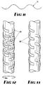
- the next stage is to place cable 23 into an open moulding die 24, the open die 24 having an internal 'U'-shape which includes inner parallel side walls 25, a concave base 26 joining the inner side walls 25, and containing recesses 27 for the formation of outstanding projections 28 as shown in Figs. 12 and 13, the die including at least one movable die part 29 having parallel side walls 30 which slidably engage the inner side walls 25.
- Each die part has a thread form 31 the contour of which is generally sinusoidal as shown in Fig. 11
- a male insert 32 is inserted into an end of wetted cable 23 after the die is closed.
- a cylindrical insert is used. This has the effect of forcing the formerly straight fibreglass strands 20 up into the female thread form to partly conform to its contours.
- the insert can subsequently be removed and be replaced by settable resin, it is preferred that the insert should remain in the rod after moulding, and desirable but not essential that the cross-sectional area of the insert be such that the cross-section of fibre reinforced plastic in the annulus surrounding the insert should equal the cross-sectional area of the shank of the fastener.
- FIGs. 5 and 6 illustrate the enlarged threaded end 33 of the fastener, and the thread terminates in a short parallel portion 34 of the fastener, which itself merges into a tapered portion 35, and finally a parallel portion 36 from which the projections 28 are outstanding. Tests have indicated that this arrangement reduces incidence of stress concentration failure in the fastener, since there is a smooth transition of direction of fibreglass strands 20.
- a three part die may be used as shown in Fig. 4.
- the open die 24 comprises two portions 24a and 24b which are laterally separable to allow release of the threads 31 and projections 28.
- the die may be as shown in Fig. 3 for the length of the shank, but may include a conventional die portion at the threaded end where the diameter of the cable is expanded, since pressure is not applied at that end until after the die is closed.
- Fig. 6 illustrates to a much larger scale the form of the thread 31 wherein the wetted fibres 20 will be seen to have taken a shape approximately corresponding to the outer surface of the thread.
- Fig. 7 illustrates an injecting head 38 insertable into an end of cable 23 in the same way as dowel 32. If settable polymeric material is injected through the head 38, and the head withdrawn, the settable material remains as a male insert in the space created by head 38.
- An advantage of this method is that the settable material can be injected at high pressure, and further assist entry of the fibres 20 into the voids of the female thread form 31 under hydraulic pressure which is unlikely to damage the fibres.
- Fig. 8 is a diagrammatic representation of a production line wherein, after moulding and setting of a fastener in a three part die 24 as set forth above and illustrated in Fig. 4, the three parts 24a, 24b and 29 are separated, the set fastener is drawn out of the die 24 by windlass 39, and a further portion of wetted cable 23 (in two parts) is drawn into die 24 before its reclosure.
- Injection head 38 is inserted into the entry end of die 24 after closure of die 24 but before setting of the resin, valve 40 is opened to inject a settable dough moulding compound through head 38, from pressure vessel 41 (or an equivalent, e.g. accumulator). After setting and withdrawal from die 24, the resin continues to cure until it has hardened sufficiently to be severed by saw 42.
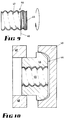
- Figs. 9 and 10 illustrate the production of a nut 44 (also shown in Fig. 5).
- a mandrel 45 is provided with a thread form 46 corresponding to the thread form 31 but having a very slightly greater pitch.
- a layer of woven reinforcement material 47 is laid up over the mandrel 45, with the warp threads extending longitudinally and the weft threads extending circumferentially.
- the warp threads should be of sufficient strength to provide the longitudinal reinforcement for the screw thread.
- the nut of course is also subject to considerable hoop stress, and to provide hoop stress reinforcement a strand 48 is wound in spiral fashion over the woven reinforcement material 47.
- the external nut shape is achieved in a pressure die 49, the die 49 being closed over added dough moulding compound, sheet moulding compound, or catalysed resin 46 which overlies the reinforced thread, and the mandrel 45 is removed (after the resin is at least partly cross-linked).
- the reinforced nut is arranged to have a slightly less modulus of elasticity than the reinforced rod so that the load applied will be more evenly spread over the length of the nut.
- the nut may be made slightly longer and moulded from dough or sheet moulding compound.
- Figs. 12 and 13 illustrate alternative shapes and configurations of the ribs 26 on a shank of an elongate fastener which can be used in mining operations.
- the ribs 26 are part-helical, discontinuous and staggered, and alternately right/left hand helical.
- Fig. 14 shows the advantage of using a large number of fibres, and in a fibreglass/polyester combination it is desirable to have not less than 10%, but not more than 80% fibreglass by weight of the rod 23.
- Fig. 15 illustrates that the shanks of threaded rods made in accordance with this invention can have strengths which are at least comparable with mild steel nuts and bolts.
- a male insert 50 has a tapered leading end 51 (as in the case of dowel 31), and the outer surface 52 of the insert 50 has a thread form of the same pitch, but smaller diameter, than the required outer surface 53 of the thread to be formed.
- the cable is placed into die 24, which is closed, and the insert 50, with or without additional strands wound over the outer surface 53, is screwed into the cable end, whereby the cable is forced out into the conformations of the die 24, and the reinforcing fibres at least partly conform to the thread shape.
- This method again retains the constant cross-sectional area of the fibre reinforced plastics.
- the fibre displacement into the thread form is particularly consistent with this method, and the resin/fibre matrix remains substantially void-free.
Landscapes
- Engineering & Computer Science (AREA)
- Mechanical Engineering (AREA)
- Chemical & Material Sciences (AREA)
- Composite Materials (AREA)
- Moulding By Coating Moulds (AREA)
Claims (17)
- Verfahren zur Herstellung eines faserverstärkten polymeren Befestigungsmittels, das an einem Ende Befestigungsflächen aufweist, mit den Verfahrensschritten:(a) Benetzen mehrerer Verstärkungsfasern (20) mit wärmehärtbarem polymerem Harz (22),(b) Zusammenfügen der benetzten Fasern zur Bildung eines benetzten kohärenten Stranges (23), gekennzeichnet durch:(c) zumindest teilweises Einlegen des benetzten kohärenten Stranges (23) in eine Ausnehmung eines ersten Teiles einer Gußform mit U-Profil (24); die Ausnehmung hat parallele innere Seitenwände (25) und eine erste konkave Gußformfläche, die in einem Basisteil (26) angeordnet ist und in die inneren Seitenwände übergeht, wobei der Basisteil (26) nahe einem Ende der Ausnehmung passende Konturen (31) der Befestigungsflächen aufweist,(d) Verschließen des ersten Teiles durch einen zweiten beweglichen Teil (29) der Gußform, der äußere Seitenwände (30) aufweist, die zwischen die parallelen inneren Seitenwände (25) der Ausnehmung gleiten, sowie eine zweite konkave Gußformfläche, die in die parallelen äußeren Seitenwände übergeht, wobei die zweite Gußformfläche an dem einen Ende ebenfalls passende Konturen (31) der Befestigungsflächen aufweist, und Beaufschlagen der Gußformteile mit Druck zwecks Verformung der benetzten Fasern (20), so daß sich das Harz den passenden Konturen anpaßt und sich die Fasern (20) zumindest teilweise in diese Konturen einschmiegen, und(e) zumindest teilweises Aushärtenlassen des Harzes, Öffnen der Gußform (24) und Entfernen des Befestigungsmittels aus der Form.
- Verfahren nach Anspruch 1,
dadurch gekennzeichnet, daß die Form (24) eine zweiteilige Form ist und Querschnitte der passenden Konturen den Abstand zwischen den inneren Seitenwänden (25) nicht übersteigen, wobei nach dem Verfahren das Befestigungsmittel derart geformt wird, daß es zwei an den inneren Seitenwänden (25) anliegende ebene Flächen (37) aufweist, und wobei das Befestigungsmittel aus dem Raum zwischen den inneren Seitenwänden (25) in zu diesen Seitenwänden paralleler Richtung aus der Form (24) entfernt wird. - Verfahren nach Anspruch 1,
dadurch gekennzeichnet, daß der erste Teil der Gußform (24) seinerseits aus zwei Teilen (24a, 24b) besteht, die in einer Ebene voneinander zu trennen sind, die sich mittig zwischen und parallel zu den inneren Seitenwänden (25) erstreckt, und daß die lichte Weite der passenden Konturen (31) den Abstand zwischen den inneren Seitenwänden (25) übersteigt, wobei nach dem Verfahren das Befestigungsmittel derart geformt wird, daß es Befestigungsflächen (31) aufweist, von denen es völlig umschlossen ist, und wobei das Befestigungsmittel durch Trennen der Gußformteile (24, 29) und Trennen der Teile (24a, 24b) des ersten Gußformteiles (24) aus der Form entfernt wird. - Verfahren nach Anspruch 3,
gekennzeichnet durch Entfernen des Befestigungsmittels aus der Form durch Anlegen von Zugspannung an das Befestigungsmittel, wodurch auch der benetzte kohärente Strang (23) weiter in den Raum zwischen den Gußformteilen (24, 29) hineingezogen wird, Wiederholen des Formverfahrens und Entfernen eines weiteren Befestigungsmittels sowie anschließendes Abschneiden des ersten geformten Befestigungsmittels von dem weiteren Befestigungsmittel. - Verfahren nach Anspruch 1,
gekennzeichnet durch Einsetzen eines positiven Einsatzes (32) in ein Ende des benetzten kohärenten Stranges (23), während sich dieser in der Gußform befindet und die Gußformteile (24, 29) geschlossen werden, um den Durchmesser dieses Endes zu vergrößern und zu bewirken, daß sich einige Fasern des Strangendes in die passenden Konturen (31) hineinschmiegen. - Verfahren nach Anspruch 5,
dadurch gekennzeichnet, daß die Konturen Gewindekonturen (31) sind, und daß der positive Einsatz (32) ein Außengewinde aufweist, das dieselbe Steigung wie die Konturen (31) hat, dessen Durchmesser jedoch geringer ist, und daß der positive Einsatz (32) in das Ende des benetzten kohärenten Stranges (23) eingeschraubt wird. - Verfahren nach Anspruch 3,
dadurch gekennzeichnet, daß der positive Einsatz (32) ein Keil ist, und daß der Keil in axialer Richtung in das Strangende hineingedrückt wird. - Verfahren nach Anspruch 3,
dadurch gekennzeichnet, daß der positive Einsatz (50) ein Außengewinde (52) aufweist, und daß der Einsatz (50) in das Strangende eingeschraubt wird. - Verfahren nach Anspruch 3,
gekennzeichnet durch Einsetzen eines Spritzkopfes (38) in das Strangende, Einspritzen eines härtbaren polymeren Stoffes durch den Spritzkopf (38) in das Strangende und Herausziehen des Spritzkopfes. - Verfahren nach Anspruch 1,
dadurch gekennzeichnet, daß jede Gußformfläche ebenfalls passende Konturen (27) mit spiralförmigen Vorsprüngen (28) aufweist, und daß das Befestigungsmittel derart geformt wird, daß es einen Schaft mit mehreren spiralförmigen Vorsprüngen aufweist, die den Schaft jeweils zumindest teilweise umschließen. - Verfahren nach Anspruch 10,
dadurch gekennzeichnet, daß abwechselnd vorspringende Konturen (27) zumindest einiger Konturen gegensinnig gewendelt sind. - Verfahren nach Anspruch 10,
dadurch gekennzeichnet, daß zumindest einige nebeneinanderliegende vorspringende Konturen (27) gleichsinnig gewendelt sind. - Verfahren nach Anspruch 1,
dadurch gekennzeichnet, daß zumindest einige passende Konturen Gewindekonturen (31) sind. - Verfahren nach Anspruch 13,
dadurch gekennzeichnet, daß das Profil der Gewindekonturen (31) im wesentlichen sinusförmig ist. - Kombination aus einem faserverstärkten polymeren Befestigungsmittel, das nach dem Verfahren nach Anspruch 1 hergestellt wird und einen Schaft relativ geringen Durchmessers hat, der an einem Ende ein Gewinde (31) relativ großen Durchmessers aufweist, wobei sich Fasern (20) in die Konturen des Gewindes einlegen,
und einer faserverstärkten polymeren Mutter (44), die einen niedrigeren Elastizitätsmodul als das Befestigungsmittel hat und auf das Gewinde (31) des Befestigungsmittels aufgeschraubt ist. - Kombination nach Anspruch 15,
bei der der Schaft herausstehende Vorsprünge (28) aufweist, wobei abwechselnde Vorsprünge zumindest einiger Vorsprünge gegensinnig gewendelt sind. - Kombination nach Anspruch 15,
bei der der Schaft herausstehende Vorsprünge (28) aufweist, wobei abwechselnde Vorsprünge zumindest einiger Vorsprünge gleichsinnig gewendelt sind.
Applications Claiming Priority (2)
| Application Number | Priority Date | Filing Date | Title |
|---|---|---|---|
| AUPJ468689 | 1989-06-14 | ||
| AU4686/89 | 1989-06-14 |
Publications (2)
| Publication Number | Publication Date |
|---|---|
| EP0403940A1 EP0403940A1 (de) | 1990-12-27 |
| EP0403940B1 true EP0403940B1 (de) | 1994-05-11 |
Family
ID=3773984
Family Applications (1)
| Application Number | Title | Priority Date | Filing Date |
|---|---|---|---|
| EP90111148A Expired - Lifetime EP0403940B1 (de) | 1989-06-14 | 1990-06-13 | Hochfeste Befestigungsmittel aus faserverstärkten Polymeren mit Gewinden, zum Beispiel Schraubenmutter und -bolzen |
Country Status (5)
| Country | Link |
|---|---|
| US (1) | US5152945A (de) |
| EP (1) | EP0403940B1 (de) |
| AU (1) | AU631881B2 (de) |
| CA (1) | CA2018966C (de) |
| DE (1) | DE69008777T2 (de) |
Families Citing this family (24)
| Publication number | Priority date | Publication date | Assignee | Title |
|---|---|---|---|---|
| GB2267249B (en) * | 1991-11-01 | 1996-01-24 | Applied Res Australia | Polymeric mouldings reinforced with tows of fibres |
| AU672143B2 (en) * | 1991-11-01 | 1996-09-19 | Applied Research Of Australia Pty Ltd | Polymeric mouldings reinforced with tows of fibres |
| US5567374A (en) * | 1991-11-01 | 1996-10-22 | Applied Research Of Australia, Pty. Ltd. | Polymeric moldings reinforced with tows of fibers |
| AU654594B2 (en) * | 1991-11-01 | 1994-11-10 | Applied Research Of Australia Pty Ltd | Polymeric mouldings reinforced with tows of fibres |
| DE4209265A1 (de) * | 1991-12-21 | 1993-06-24 | Dyckerhoff & Widmann Ag | Vorrichtung zur verankerung eines stabfoermigen zugglieds aus faserverbundwerkstoff |
| US5609806A (en) * | 1994-06-28 | 1997-03-11 | Reichhold Chemicals, Inc. | Method of making prepreg |
| US5763042A (en) * | 1994-06-28 | 1998-06-09 | Reichhold Chemicals, Inc. | Reinforcing structural rebar and method of making the same |
| WO1996016792A1 (en) * | 1994-12-01 | 1996-06-06 | Applied Research Of Australia Pty. Ltd. | Inhibiting resin expulsion during molding of elongate fiber reinforced products |
| DE19544804C2 (de) * | 1995-12-01 | 2001-06-13 | Mtu Aero Engines Gmbh | Verfahren zur Herstellung einer Anschlußverbindung an einem Verbundbauteil, das durch Fasern oder Fäden verstärkt ist |
| DE69710202D1 (de) | 1996-10-07 | 2002-03-14 | Marshall Ind Composites Lima | Verstärkter verbundgegenstand und vorrichtung und verfahren zu seiner herstellung |
| US6800164B2 (en) * | 2000-04-06 | 2004-10-05 | Randel Brandstrom | Method of making a fiber reinforced rod |
| ITMI20031066A1 (it) * | 2003-05-28 | 2004-11-29 | Top Glass Spa | Procedimento per conferire una forma finale ad una barra. |
| US20060090416A1 (en) * | 2004-10-29 | 2006-05-04 | Schock Bauteile Gmbh | Reinforcing element for concrete construction |
| US7862585B2 (en) * | 2005-06-23 | 2011-01-04 | Johnson & Johnson | Tissue repair device and fabrication thereof |
| US7641836B2 (en) * | 2005-06-23 | 2010-01-05 | Ethicon, Inc. | Tissue repair device and fabrication thereof |
| US7622068B2 (en) * | 2005-06-23 | 2009-11-24 | Ethicon, Inc. | Tissue repair device and fabrication thereof |
| US20060293675A1 (en) * | 2005-06-23 | 2006-12-28 | Zhigang Li | Tissue repair device and fabrication thereof |
| WO2008124885A1 (en) * | 2007-04-17 | 2008-10-23 | Phillip Hanford Boot | Plastic rock-bolt or dowel and method of manufacture of the same |
| DE102007027015A1 (de) * | 2007-06-08 | 2008-12-11 | Schöck Bauteile GmbH | Bewehrungsstab |
| GB2473007B (en) * | 2009-08-26 | 2012-11-21 | Messier Dowty Ltd | Apparatus comprising an end fitting connected to a body |
| MX391384B (es) | 2011-08-30 | 2025-03-21 | Johnson Controls Tech Co | Sistema y método para fabricar un componente de guarnición para vehículo mediante moldeo por conformación e inyección por compresión concurrente. |
| US10464280B2 (en) | 2011-08-30 | 2019-11-05 | Shanghai Yanfeng Jinqiao Automotive Trim Systems Co. Ltd. | Trim component for vehicle interior |
| US10093268B2 (en) | 2012-08-27 | 2018-10-09 | Shanghai Yanfeng Jinqiao Automotive Trim Systems Co. Ltd. | Trim component for vehicle interior |
| WO2020006290A1 (en) | 2018-06-28 | 2020-01-02 | Shanghai Yanfeng Jinqiao Automotive Trim Systems Co. Ltd. | Vehicle trim component |
Family Cites Families (9)
| Publication number | Priority date | Publication date | Assignee | Title |
|---|---|---|---|---|
| US3283050A (en) * | 1965-04-06 | 1966-11-01 | Universal Moulded Fiber Glass | Method and apparatus for making continuous lengths of threaded fiber reinforced resin articles |
| US3651188A (en) * | 1969-04-21 | 1972-03-21 | Vaughan & Bushnell Mfg Co | Method of producing a hollow hammer handle with longitudinally tensioned fibers |
| US4292101A (en) * | 1979-03-05 | 1981-09-29 | Reichert James B | Method of fabricating composite members |
| GB2108900B (en) * | 1981-11-12 | 1985-07-24 | Edwin E Conley | Fibre-reinforced sucker rod |
| ATE36035T1 (de) * | 1985-01-17 | 1988-08-15 | Weidmann H Ag | Anker zur sicherung von waenden in hohlraumbauten. |
| JP2664446B2 (ja) * | 1988-12-16 | 1997-10-15 | フクビ化学工業株式会社 | 合成樹脂製螺子の製造方法 |
| JPH02286226A (ja) * | 1989-04-27 | 1990-11-26 | Fukuvi Chem Ind Co Ltd | 合成樹脂製締結部材の製造方法 |
| JPH0759383B2 (ja) * | 1988-12-16 | 1995-06-28 | フクビ化学工業株式会社 | 合成樹脂製螺子の製造方法 |
| JP2664445B2 (ja) * | 1988-12-16 | 1997-10-15 | フクビ化学工業株式会社 | 合成樹脂製螺子の製造方法 |
-
1990
- 1990-06-13 EP EP90111148A patent/EP0403940B1/de not_active Expired - Lifetime
- 1990-06-13 AU AU56990/90A patent/AU631881B2/en not_active Expired
- 1990-06-13 DE DE69008777T patent/DE69008777T2/de not_active Expired - Lifetime
- 1990-06-13 CA CA002018966A patent/CA2018966C/en not_active Expired - Lifetime
- 1990-06-20 US US07/541,270 patent/US5152945A/en not_active Expired - Lifetime
Also Published As
| Publication number | Publication date |
|---|---|
| AU5699090A (en) | 1990-12-20 |
| DE69008777D1 (de) | 1994-06-16 |
| AU631881B2 (en) | 1992-12-10 |
| CA2018966A1 (en) | 1990-12-14 |
| CA2018966C (en) | 2001-01-16 |
| US5152945A (en) | 1992-10-06 |
| DE69008777T2 (de) | 1994-12-08 |
| EP0403940A1 (de) | 1990-12-27 |
Similar Documents
| Publication | Publication Date | Title |
|---|---|---|
| US5152945A (en) | High strength fiber reinforced polymeric fasteners having threads, for example a nut and bolt | |
| US4861197A (en) | Roof bolt system | |
| CA1270670A (en) | Anchoring system for the tension member of an anchor, particularly a rock anchor | |
| US5437830A (en) | Process of making a rod for use in reinforcing an underground rock formation | |
| RU2078258C1 (ru) | Анкер для закрепления в просверленном в бетонном элементе отверстии с помощью композитной массы | |
| US5437526A (en) | Arrangement for anchoring a rod-shaped tension member of composite fiber material | |
| CN101413397A (zh) | 自钻孔岩石锚杆 | |
| US4584247A (en) | Threading deformed bars | |
| US7645096B2 (en) | Yielding rock bolt | |
| GB2295572A (en) | Moulding fibre-reinforced products | |
| CN111594242A (zh) | 预应力涨壳锚杆及其施工方法 | |
| RU2178082C2 (ru) | Канатный анкер | |
| US5775850A (en) | Rock bolt | |
| US20100290840A1 (en) | Plastic rock-bolt or dowel and method of manufacturing of the same | |
| US7296950B1 (en) | Point anchor coated mine roof bolt | |
| US20250305416A1 (en) | Rock bolt installation | |
| RU2202042C2 (ru) | Канатный анкер | |
| US20030031525A1 (en) | Resin embedded rock bolt | |
| AU2014203249A1 (en) | Rock bolt | |
| AU2003287766B2 (en) | A yielding rock bolt | |
| AU2021218166B2 (en) | Rock bolt | |
| CN112065480B (zh) | 隧道掌子面可循环利用式超前灌浆锚索及其应用方法 | |
| CN121781960A (zh) | 一种基于复合材料的机械扩张式锚杆系统及其施工方法 | |
| CA2182492C (en) | Inhibiting resin expulsion during molding of elongate fiber reinforced products | |
| AU677089B2 (en) | A rock bolt |
Legal Events
| Date | Code | Title | Description |
|---|---|---|---|
| PUAI | Public reference made under article 153(3) epc to a published international application that has entered the european phase |
Free format text: ORIGINAL CODE: 0009012 |
|
| AK | Designated contracting states |
Kind code of ref document: A1 Designated state(s): CH DE FR GB LI |
|
| 17P | Request for examination filed |
Effective date: 19910615 |
|
| 17Q | First examination report despatched |
Effective date: 19920807 |
|
| GRAA | (expected) grant |
Free format text: ORIGINAL CODE: 0009210 |
|
| AK | Designated contracting states |
Kind code of ref document: B1 Designated state(s): CH DE FR GB LI |
|
| PG25 | Lapsed in a contracting state [announced via postgrant information from national office to epo] |
Ref country code: CH Effective date: 19940511 Ref country code: LI Effective date: 19940511 |
|
| REF | Corresponds to: |
Ref document number: 69008777 Country of ref document: DE Date of ref document: 19940616 |
|
| ET | Fr: translation filed | ||
| REG | Reference to a national code |
Ref country code: CH Ref legal event code: PL |
|
| PLBE | No opposition filed within time limit |
Free format text: ORIGINAL CODE: 0009261 |
|
| STAA | Information on the status of an ep patent application or granted ep patent |
Free format text: STATUS: NO OPPOSITION FILED WITHIN TIME LIMIT |
|
| 26N | No opposition filed | ||
| REG | Reference to a national code |
Ref country code: GB Ref legal event code: IF02 |
|
| PGFP | Annual fee paid to national office [announced via postgrant information from national office to epo] |
Ref country code: FR Payment date: 20090615 Year of fee payment: 20 |
|
| PGFP | Annual fee paid to national office [announced via postgrant information from national office to epo] |
Ref country code: GB Payment date: 20090618 Year of fee payment: 20 Ref country code: DE Payment date: 20090622 Year of fee payment: 20 |
|
| REG | Reference to a national code |
Ref country code: GB Ref legal event code: PE20 Expiry date: 20100612 |
|
| PG25 | Lapsed in a contracting state [announced via postgrant information from national office to epo] |
Ref country code: GB Free format text: LAPSE BECAUSE OF EXPIRATION OF PROTECTION Effective date: 20100612 |
|
| PG25 | Lapsed in a contracting state [announced via postgrant information from national office to epo] |
Ref country code: DE Free format text: LAPSE BECAUSE OF EXPIRATION OF PROTECTION Effective date: 20100613 |