EP0403467A2 - Anti-aliasing optical system - Google Patents
Anti-aliasing optical system Download PDFInfo
- Publication number
- EP0403467A2 EP0403467A2 EP90890178A EP90890178A EP0403467A2 EP 0403467 A2 EP0403467 A2 EP 0403467A2 EP 90890178 A EP90890178 A EP 90890178A EP 90890178 A EP90890178 A EP 90890178A EP 0403467 A2 EP0403467 A2 EP 0403467A2
- Authority
- EP
- European Patent Office
- Prior art keywords
- optical
- low
- aliasing
- pass filter
- pyramidal structure
- Prior art date
- Legal status (The legal status is an assumption and is not a legal conclusion. Google has not performed a legal analysis and makes no representation as to the accuracy of the status listed.)
- Withdrawn
Links
Images
Classifications
-
- G—PHYSICS
- G02—OPTICS
- G02B—OPTICAL ELEMENTS, SYSTEMS OR APPARATUS
- G02B27/00—Optical systems or apparatus not provided for by any of the groups G02B1/00 - G02B26/00, G02B30/00
- G02B27/42—Diffraction optics, i.e. systems including a diffractive element being designed for providing a diffractive effect
- G02B27/46—Systems using spatial filters
Definitions
- the present invention pertains to an optical, low-pass filter, anti-aliasing apparatus and, in particular, to an optical, low-pass filter, anti-aliasing apparatus for use with a focal plane array such as an image sensing device, for example, a solid-state image sensing device using a CCD (charge-coupled device) or the like, which produces a predetermined image pickup output by carrying out spatial sampling.
- a focal plane array such as an image sensing device, for example, a solid-state image sensing device using a CCD (charge-coupled device) or the like, which produces a predetermined image pickup output by carrying out spatial sampling.
- a color video camera typically produces a color signal output corresponding to the viewed object scene by color coding an image of the object scene with a color filter which is disposed at the front of the video camera and by spatially sampling each color using an array of photosensitive elements such as, for example, a CCD, as a solid-state image sensing device.
- a CCD photosensitive elements
- an imaging system it is well known that components in the object scene which contain frequencies too large to be analyzed with the sampling interval used contribute to the amplitudes of lower frequency components and produce, thereby, image errors which are referred to in the art as aliasing distortion or undersampling artifacts.
- an optical system for the array can eliminate aliasing if it has a frequency response which cuts out the higher frequency content of the object scene.
- an optical apparatus such as, for example, a birefringent blur filter has become a common component in consumer color video cameras.
- Such apparatus are typically placed between a lens and the photosensor array to provide a low-pass filter function which reduces the spatial frequency content of the object scene at frequencies above the Nyquist frequency of the photosensor array to make the imaging system less susceptible to aliasing distortion.
- an achromatic low-pass filter or "blur" is effective in minimizing aliasing distortion.
- optical low-pass filter for a Single-Vidicon Color Television Camera
- M. Mino and Y. Okano in Journal of the SMPTE , Vol. 81, April, 1972, pp. 282-285 describes several desirable conditions which an optical low-pass filter used to remove aliasing distortion should satisfy.
- one condition is that the optical low-pass filter should preferably be a phase filter which does not diminish the light level in the transmitted light.
- Another condition for the optical low-pass filter is that its effect should be independent of the aperture of the optical imaging system. In addition to these conditions, one may add the condition that the optical low-pass filter be easily manufactured at a relatively low cost.
- an aliasing suppression phase filter which is commonly used in commercially available video cameras is a birefringent blur filter.
- a birefringent blur filter is typically made of crystalline quartz wherein the crystal axis of the filter plates are oriented at about a 45° angle with respect to the surface. In this orientation, the birefringent quartz exhibits the double-refraction effect, and an unpolarized input ray passing into the filter emerges as two polarized output rays.
- This type of filter suffers from the drawback that it is rather expensive, and it is also rather complicated to manufacture.
- optical noise phase filter which is comprised of statistically distributed phase elements.
- the optical noise filter suffers from a drawback in that it becomes difficult for the phase elements to be distributed statistically as the aperture stop of the objective lens of the imaging system is reduced.
- phase diffraction grating can be used as a frequency selective filter.
- a grating is frequency selective, and the size of the grating is restricted by the objective aperture stop.
- gratings are rather expensive and are also rather complicated to manufacture.
- Embodiments of the present invention satisfy the above-described need by providing a wavelength independent, optical, low-pass phase filter which is effective at substantially all aperture stops of an optical imaging system and which is relatively simple and inexpensive to manufacture.
- an embodiment of the inventive optical apparatus comprises a substantially transparent, convex, pyramidal structure comprised of four shallow, wedge-like protrusions or a substantially transparent, concave, pyramidal structure comprised of four shallow, wedge-like depressions.
- the wedge-like protrusions of the pyramidal structure are formed from barium fluoride (BaF2) which has been coated with magnesium fluoride (MgF2) to prevent absorption of H2O.
- BaF2 barium fluoride
- MgF2 magnesium fluoride
- the pyramidal structure may be formed on a glass plate, a plastic plate or even on the surface of a lens.
- the pyramidal structure may be fabricated by pressing a softened material as, for example, a plastic material against a harder surface coating of a structure having a form which will provide either the desired convex or concave pyramidal structure in the softened material.
- the inventive apparatus is preferably used by placing it in the aperture stop plane or its image where the iris would also be conveniently located for an optical imaging system. This placement ensures that the iris of the aperture stop can be opened or closed while the inventive apparatus provides substantially the same amount of low-pass filtering action.
- the wedge angle of a particular wedge portion of the inventive pyramidal structure determines the amount by which the light passing therethrough is shifted in direction.
- wedges disposed on opposite sides of the inventive pyramidal structure will shift the light passing therethrough in opposite directions.
- the wedge angles of the pyramidal structure are made large enough to shift the light passing through the structure so that on average it impinges simultaneously on several pixels or sensors in the photosensor array. This causes a blurring effect which provides a spatial low-pass filter.
- apparatus 100 comprises wedges or tetrahedra 101-104 which are disposed on glass plate 110.
- Wedges 101- 104 are comprised of barium fluoride (BaF2) which has been coated with a layer of magnesium flouride (MgF2) to prevent the absorption of H2O.
- BaF2 barium fluoride
- MgF2 magnesium flouride
- Pyramidal apparatus 100 is fabricated in accordance with methods well known to those of ordinary skill in the art. Specifically, in one embodiment, pyramidal apparatus 100 is formed by vacuum depositing BaF2 upon glass plate 110 through a square mask. The aperture provided by the square mask is gradually diminished so that the area of glass plate 110 which is exposed to vacuum deposition of the BaF2 is also gradually diminished. Then, in accordance with methods well known to those of ordinary skill in the art, an MgF2 coating is applied to the BaF2 pyramid structure by vacuum deposition. As one can readily appreciate, this method of fabrication provides a optical apparatus which is substantially wavelength independent and which is substantially transparent to light passing therethrough.
- FIG. 2 shows optical apparatus 100 disposed in aperture stop plane 150, substantially at the iris, of an optical system 200.
- Optical system 200 is used to image an object scene onto photosensor array 250 which is comprised of spaced apart photosensor elements, also referred to as pixels.
- apparatus 100 is placed at the opening of adjustable iris in the form of two counter-reciprocating shutter blades 190 located substantially at or near the aperture stop plane 150 between senses 170 and 180 of optical system 200. Diverging lens 180 spreads the light passing between lens 160 and 170 a sufficient amount so that substantially one-quarter of the incident light which passes through optical system 200 passes through each of wedges 101-104 of apparatus 100.
- adjustable iris 190 at aperture stop plane 150 of optical system 200 can be opened or closed while apparatus 100 provides substantially the same amount of low-pass filtering action.
- each wedge 101-104 of inventive apparatus 100 Approximately one-quarter of the incident light passes through each wedge 101-104 of inventive apparatus 100, and the wedge angle of each wedge determines the amount by which the light passing therethrough is shifted in direction.
- wedges disposed on opposite sides of apparatus 100 for example, wedges 101 and 103 and wedges 102 and 104, shift the light passing therethrough in opposite directions.
- the light which passes through apparatus 100 is shifted so that it impinges, on the average, simultaneously upon several elements or pixels in photosensor array 250.
- This causes a blurring effect which provides a spatial low-pass filter. That is, light from an object scene which passes through each of the wedges is angled slightly away from light which passes through the other wedges.
- the thickness of wedges 101-104 at the center and, hence, the wedge angles is made to be sufficiently large so that the desired blur of light which passes therethrough is obtained at photosensor array 250.
- an embodiment of the present invention which comprises a substantially transparent, convex, pyramidal structure comprised of four shallow, wedge-like protrusions
- the present invention is not limited to such embodiments.
- further embodiments of the present invention comprise a substantially transparent, concave, pyramidal structure comprised of four shallow, wedge-like depressions.
- embodiments of the convex or concave inventive pyramidal structure may be fabricated by pressing a softened material such as, for example, a plastic material, against a harder surface coating of a structure having a form which will provide either the desired convex or concave pyramidal structure in the softened material.
- a softened material such as, for example, a plastic material
- embodiments of the present invention are not limited to the formation of a pyramidal structure upon or in a plate and, in fact, further embodiments of the present invention comprise the formation of the pyramidal structure directly on a lens.
- wedges may each be fabricated separately and glued together to provide a convex, pyramidal structure. In such a case, it is advantageous to polish the outer surface of the completed apparatus after the pieces have been joined.
- the pyramid For use with very small apertures, such that the diffraction blur of the aperture itself can accomplish the anti-aliasing function, the pyramid would be flattened at the very center, forming a frustrum.
Abstract
Description
- The present invention pertains to an optical, low-pass filter, anti-aliasing apparatus and, in particular, to an optical, low-pass filter, anti-aliasing apparatus for use with a focal plane array such as an image sensing device, for example, a solid-state image sensing device using a CCD (charge-coupled device) or the like, which produces a predetermined image pickup output by carrying out spatial sampling.
- A color video camera typically produces a color signal output corresponding to the viewed object scene by color coding an image of the object scene with a color filter which is disposed at the front of the video camera and by spatially sampling each color using an array of photosensitive elements such as, for example, a CCD, as a solid-state image sensing device. In such an imaging system, it is well known that components in the object scene which contain frequencies too large to be analyzed with the sampling interval used contribute to the amplitudes of lower frequency components and produce, thereby, image errors which are referred to in the art as aliasing distortion or undersampling artifacts.
- In general, an optical system for the array can eliminate aliasing if it has a frequency response which cuts out the higher frequency content of the object scene. As a result, it is well known in the prior art that the design of electronic imaging systems involves a trade-off between image sharpness and the susceptibility of the imaging system to aliasing distortions or undersampling artifacts. To effect this trade-off, an optical apparatus such as, for example, a birefringent blur filter has become a common component in consumer color video cameras. Such apparatus are typically placed between a lens and the photosensor array to provide a low-pass filter function which reduces the spatial frequency content of the object scene at frequencies above the Nyquist frequency of the photosensor array to make the imaging system less susceptible to aliasing distortion. For example, for many available sensors wherein equal pixel densities in each of the sensed colors provide that each of the sensed colors have the same Nyquist frequency, an achromatic low-pass filter or "blur" is effective in minimizing aliasing distortion.
- An article entitled "Optical Low-Pass Filter for a Single-Vidicon Color Television Camera" by M. Mino and Y. Okano, in Journal of the SMPTE, Vol. 81, April, 1972, pp. 282-285 describes several desirable conditions which an optical low-pass filter used to remove aliasing distortion should satisfy. Specifically, one condition is that the optical low-pass filter should preferably be a phase filter which does not diminish the light level in the transmitted light. Another condition for the optical low-pass filter is that its effect should be independent of the aperture of the optical imaging system. In addition to these conditions, one may add the condition that the optical low-pass filter be easily manufactured at a relatively low cost.
- In the art, many attempts have been made to provide apparatus to low-pass filter the spatial frequency of an object scene. However, each of these has at least one drawback. For example, an aliasing suppression phase filter which is commonly used in commercially available video cameras is a birefringent blur filter. Such a filter is typically made of crystalline quartz wherein the crystal axis of the filter plates are oriented at about a 45° angle with respect to the surface. In this orientation, the birefringent quartz exhibits the double-refraction effect, and an unpolarized input ray passing into the filter emerges as two polarized output rays. This type of filter suffers from the drawback that it is rather expensive, and it is also rather complicated to manufacture.
- Another example which is well known in the art is an optical noise phase filter which is comprised of statistically distributed phase elements. The optical noise filter suffers from a drawback in that it becomes difficult for the phase elements to be distributed statistically as the aperture stop of the objective lens of the imaging system is reduced.
- In addition to the birefringent blur filter and the optical phase noise filter briefly discussed above, it is well known in the art that a phase diffraction grating can be used as a frequency selective filter. However, such a grating is frequency selective, and the size of the grating is restricted by the objective aperture stop. In addition, such gratings are rather expensive and are also rather complicated to manufacture.
- As one can readily appreciate from the above, there is a need in the art for an optical, low-pass, phase filter which is effective at substantially all aperture stops of an optical imaging system and which is relatively simply and inexpensive to manufacture.
- Embodiments of the present invention satisfy the above-described need by providing a wavelength independent, optical, low-pass phase filter which is effective at substantially all aperture stops of an optical imaging system and which is relatively simple and inexpensive to manufacture. In particular, an embodiment of the inventive optical apparatus comprises a substantially transparent, convex, pyramidal structure comprised of four shallow, wedge-like protrusions or a substantially transparent, concave, pyramidal structure comprised of four shallow, wedge-like depressions.
- In a preferred embodiment of the convex, pyramidal structure of the present invention, the wedge-like protrusions of the pyramidal structure are formed from barium fluoride (BaF₂) which has been coated with magnesium fluoride (MgF₂) to prevent absorption of H₂O. Further, the pyramidal structure may be formed on a glass plate, a plastic plate or even on the surface of a lens.
- In further embodiments of the present invention, the pyramidal structure may be fabricated by pressing a softened material as, for example, a plastic material against a harder surface coating of a structure having a form which will provide either the desired convex or concave pyramidal structure in the softened material.
- The inventive apparatus is preferably used by placing it in the aperture stop plane or its image where the iris would also be conveniently located for an optical imaging system. This placement ensures that the iris of the aperture stop can be opened or closed while the inventive apparatus provides substantially the same amount of low-pass filtering action.
- In use, approximately one-quarter of the light incident upon the inventive apparatus passes through each facet of the pyramidal structure. Further, the wedge angle of a particular wedge portion of the inventive pyramidal structure determines the amount by which the light passing therethrough is shifted in direction. Still further, as one of ordinary skill in the art will readily appreciate, wedges disposed on opposite sides of the inventive pyramidal structure will shift the light passing therethrough in opposite directions. In accordance with this, the wedge angles of the pyramidal structure are made large enough to shift the light passing through the structure so that on average it impinges simultaneously on several pixels or sensors in the photosensor array. This causes a blurring effect which provides a spatial low-pass filter.
- The novel features that are considered characteristic of the present invention are set forth with particularity herein, both as to their organization and method of operation, together with other objects and advantages thereof, and will be best understood from the following description of the illustrated embodiments when read in connection with the accompanying drawings wherein:
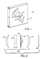
- FIG. 1 shows, in pictorial form, an embodiment of the inventive optical, low-pass filter, anti-aliasing apparatus, and
- FIG. 2 shows, in pictorial form, the use of the inventive optical, low-pass filter, anti-aliasing apparatus in the aperture stop plane of an optical system.
- Referring now to FIG. 1, there is shown at 100 an embodiment of the inventive optical, low-pass filter, anti-aliasing apparatus. Specifically,
apparatus 100 comprises wedges or tetrahedra 101-104 which are disposed onglass plate 110. Wedges 101- 104 are comprised of barium fluoride (BaF₂) which has been coated with a layer of magnesium flouride (MgF₂) to prevent the absorption of H₂O. -
Pyramidal apparatus 100 is fabricated in accordance with methods well known to those of ordinary skill in the art. Specifically, in one embodiment,pyramidal apparatus 100 is formed by vacuum depositing BaF₂ uponglass plate 110 through a square mask. The aperture provided by the square mask is gradually diminished so that the area ofglass plate 110 which is exposed to vacuum deposition of the BaF₂ is also gradually diminished. Then, in accordance with methods well known to those of ordinary skill in the art, an MgF₂ coating is applied to the BaF₂ pyramid structure by vacuum deposition. As one can readily appreciate, this method of fabrication provides a optical apparatus which is substantially wavelength independent and which is substantially transparent to light passing therethrough. - FIG. 2 shows
optical apparatus 100 disposed inaperture stop plane 150, substantially at the iris, of anoptical system 200.Optical system 200 is used to image an object scene ontophotosensor array 250 which is comprised of spaced apart photosensor elements, also referred to as pixels. Specifically, as shown in FIG. 2,apparatus 100 is placed at the opening of adjustable iris in the form of twocounter-reciprocating shutter blades 190 located substantially at or near theaperture stop plane 150 betweensenses optical system 200. Diverginglens 180 spreads the light passing betweenlens 160 and 170 a sufficient amount so that substantially one-quarter of the incident light which passes throughoptical system 200 passes through each of wedges 101-104 ofapparatus 100. As one can readily appreciate from this,adjustable iris 190 ataperture stop plane 150 ofoptical system 200 can be opened or closed whileapparatus 100 provides substantially the same amount of low-pass filtering action. - Approximately one-quarter of the incident light passes through each wedge 101-104 of
inventive apparatus 100, and the wedge angle of each wedge determines the amount by which the light passing therethrough is shifted in direction. For example, wedges disposed on opposite sides ofapparatus 100, for example,wedges 101 and 103 andwedges apparatus 100 is shifted so that it impinges, on the average, simultaneously upon several elements or pixels inphotosensor array 250. This causes a blurring effect which provides a spatial low-pass filter. That is, light from an object scene which passes through each of the wedges is angled slightly away from light which passes through the other wedges. The thickness of wedges 101-104 at the center and, hence, the wedge angles, is made to be sufficiently large so that the desired blur of light which passes therethrough is obtained atphotosensor array 250. - Although the we have described an embodiment of the present invention which comprises a substantially transparent, convex, pyramidal structure comprised of four shallow, wedge-like protrusions, the present invention is not limited to such embodiments. For example, further embodiments of the present invention comprise a substantially transparent, concave, pyramidal structure comprised of four shallow, wedge-like depressions. In addition, embodiments of the convex or concave inventive pyramidal structure may be fabricated by pressing a softened material such as, for example, a plastic material, against a harder surface coating of a structure having a form which will provide either the desired convex or concave pyramidal structure in the softened material. Instead of the preferred location of the inventive apparatus at or near the aperture stop of an imaging system, it could also be at or near the image of the aperture stop with beneficial effect.
- Other embodiments of the invention, including additions, subtractions, deletions and other modifications of the preferred disclosed embodiments of the invention will be obvious to those skilled in the art and are within the scope of the following claims. For example, it should be clear to those of ordinary skill in the art that embodiments of the present invention are not limited to the formation of a pyramidal structure upon or in a plate and, in fact, further embodiments of the present invention comprise the formation of the pyramidal structure directly on a lens. In addition, wedges may each be fabricated separately and glued together to provide a convex, pyramidal structure. In such a case, it is advantageous to polish the outer surface of the completed apparatus after the pieces have been joined.
- For use with very small apertures, such that the diffraction blur of the aperture itself can accomplish the anti-aliasing function, the pyramid would be flattened at the very center, forming a frustrum.
Claims (9)
forming a pyramidal structure in a first material;
coating the structure with a second material having a predetermined degree of hardness;
pressing a substantially transparent, softened material against the coated structure to provide the optical, low-pass, anti-aliasing apparatus in the substantially transparent material.
Applications Claiming Priority (2)
| Application Number | Priority Date | Filing Date | Title |
|---|---|---|---|
| US07/364,658 US4989959A (en) | 1989-06-12 | 1989-06-12 | Anti-aliasing optical system with pyramidal transparent structure |
| US364658 | 1989-06-12 |
Publications (2)
| Publication Number | Publication Date |
|---|---|
| EP0403467A2 true EP0403467A2 (en) | 1990-12-19 |
| EP0403467A3 EP0403467A3 (en) | 1991-03-06 |
Family
ID=23435490
Family Applications (1)
| Application Number | Title | Priority Date | Filing Date |
|---|---|---|---|
| EP19900890178 Withdrawn EP0403467A3 (en) | 1989-06-12 | 1990-06-07 | Anti-aliasing optical system |
Country Status (7)
| Country | Link |
|---|---|
| US (1) | US4989959A (en) |
| EP (1) | EP0403467A3 (en) |
| JP (1) | JPH0355981A (en) |
| CA (1) | CA2016058A1 (en) |
| DE (1) | DE403467T1 (en) |
| ES (1) | ES2020796A4 (en) |
| GR (1) | GR910300012T1 (en) |
Cited By (3)
| Publication number | Priority date | Publication date | Assignee | Title |
|---|---|---|---|---|
| WO2003079093A2 (en) * | 2002-03-14 | 2003-09-25 | Science & Engineering Associates, Inc. | Multiple imaging system and method for designing same |
| WO2007137293A2 (en) * | 2006-05-23 | 2007-11-29 | Omnivision Cdm Optics, Inc. | Saturation optics |
| KR101475529B1 (en) | 2006-04-17 | 2014-12-23 | 옴니비젼 씨디엠 옵틱스 인코퍼레이티드 | Arrayed imaging systems and associated methods |
Families Citing this family (29)
| Publication number | Priority date | Publication date | Assignee | Title |
|---|---|---|---|---|
| JP3506144B2 (en) * | 1992-10-19 | 2004-03-15 | ソニー株式会社 | Image display device and optical filter for display device |
| US5299275A (en) * | 1993-03-31 | 1994-03-29 | Eastman Kodak Company | Optical fiber filter for reducing artifacts in imaging apparatus |
| US5322998A (en) * | 1993-03-31 | 1994-06-21 | Eastman Kodak Company | Conical blur filter for reducing artifacts in imaging apparatus |
| US5438366A (en) * | 1993-03-31 | 1995-08-01 | Eastman Kodak Company | Aspherical blur filter for reducing artifacts in imaging apparatus |
| US5541653A (en) * | 1993-07-27 | 1996-07-30 | Sri International | Method and appartus for increasing resolution of digital color images using correlated decoding |
| US5353728A (en) * | 1993-12-17 | 1994-10-11 | Marine Safety Systems Inc. | Centrally-located-ballast-tank vessel |
| US6025873A (en) * | 1994-04-07 | 2000-02-15 | Olympus Optical Co., Ltd. | Endoscope system provided with low-pass filter for moire removal |
| JPH0821991A (en) | 1994-07-08 | 1996-01-23 | Sony Corp | Picture display device |
| US20020195548A1 (en) * | 2001-06-06 | 2002-12-26 | Dowski Edward Raymond | Wavefront coding interference contrast imaging systems |
| US7218448B1 (en) * | 1997-03-17 | 2007-05-15 | The Regents Of The University Of Colorado | Extended depth of field optical systems |
| US6911638B2 (en) | 1995-02-03 | 2005-06-28 | The Regents Of The University Of Colorado, A Body Corporate | Wavefront coding zoom lens imaging systems |
| US20020118457A1 (en) * | 2000-12-22 | 2002-08-29 | Dowski Edward Raymond | Wavefront coded imaging systems |
| US5682266A (en) * | 1995-04-05 | 1997-10-28 | Eastman Kodak Company | Blur filter for eliminating aliasing in electrically sampled images |
| US5684293A (en) * | 1995-11-29 | 1997-11-04 | Eastman Kodak Company | Anti-aliasing low-pass blur filter for reducing artifacts in imaging apparatus |
| US5696371A (en) * | 1996-05-23 | 1997-12-09 | Eastman Kodak Company | Diffractive/refractive lenslet array |
| US5751492A (en) * | 1996-06-14 | 1998-05-12 | Eastman Kodak Company | Diffractive/Refractive lenslet array incorporating a second aspheric surface |
| US6937283B1 (en) | 1996-12-03 | 2005-08-30 | Eastman Kodak Company | Anti-aliasing low-pass blur filter for reducing artifacts in imaging apparatus |
| US6040857A (en) * | 1997-05-27 | 2000-03-21 | Eastman Kodak Company | Phase-noise type broad spectral bandwidth optical low-pass anti-aliasing filter |
| US6326998B1 (en) * | 1997-10-08 | 2001-12-04 | Eastman Kodak Company | Optical blur filter having a four-feature pattern |
| US6021005A (en) * | 1998-01-09 | 2000-02-01 | University Technology Corporation | Anti-aliasing apparatus and methods for optical imaging |
| JP2000089114A (en) * | 1998-09-08 | 2000-03-31 | Olympus Optical Co Ltd | Zoom lens |
| US6536898B1 (en) * | 2000-09-15 | 2003-03-25 | The Regents Of The University Of Colorado | Extended depth of field optics for human vision |
| US6873733B2 (en) | 2001-01-19 | 2005-03-29 | The Regents Of The University Of Colorado | Combined wavefront coding and amplitude contrast imaging systems |
| US6842297B2 (en) | 2001-08-31 | 2005-01-11 | Cdm Optics, Inc. | Wavefront coding optics |
| US7164807B2 (en) * | 2003-04-24 | 2007-01-16 | Eastman Kodak Company | Method and system for automatically reducing aliasing artifacts |
| US7171055B2 (en) * | 2003-04-24 | 2007-01-30 | Eastman Kodak Company | Parametric means for reducing aliasing artifacts |
| US7321112B2 (en) * | 2003-08-18 | 2008-01-22 | Gentex Corporation | Optical elements, related manufacturing methods and assemblies incorporating optical elements |
| US20090096915A1 (en) * | 2007-10-16 | 2009-04-16 | Kelly Sean C | Anti-aliasing spatial filter system |
| WO2009066770A1 (en) * | 2007-11-22 | 2009-05-28 | Nikon Corporation | Digital camera and digital camera system |
Citations (3)
| Publication number | Priority date | Publication date | Assignee | Title |
|---|---|---|---|---|
| JPS55108613A (en) * | 1979-02-14 | 1980-08-21 | Minolta Camera Co Ltd | Optical low-pass filter |
| EP0038557A2 (en) * | 1980-04-18 | 1981-10-28 | Victor Company Of Japan, Ltd. | Optical low-pass filter |
| JPS61254924A (en) * | 1985-05-07 | 1986-11-12 | Ricoh Co Ltd | Optical low-pass filter |
Family Cites Families (14)
| Publication number | Priority date | Publication date | Assignee | Title |
|---|---|---|---|---|
| US1371969A (en) * | 1920-05-29 | 1921-03-15 | Furman Ira | Color-picture |
| US2200466A (en) * | 1934-01-15 | 1940-05-14 | Cristiani Luigi | Apparatus for color photography |
| US2200467A (en) * | 1938-05-12 | 1940-05-14 | Cristiani Luigi | Apparatus for color photography |
| US2527896A (en) * | 1945-01-08 | 1950-10-31 | Thirard Armand Henri Julien | Optical image separating device with plural prism for dividing the light beam for colored photography and cinematography |
| JPS517381B1 (en) * | 1970-10-14 | 1976-03-06 | ||
| JPS52100930A (en) * | 1976-02-20 | 1977-08-24 | Minolta Camera Co Ltd | Optical system of uni-tube type color tv camera using optical low-pass filter |
| JPS53119063A (en) * | 1977-03-26 | 1978-10-18 | Minolta Camera Co Ltd | Optical low pass filter |
| JPS5445152A (en) * | 1977-09-17 | 1979-04-10 | Victor Co Of Japan Ltd | Optical comb type filter |
| US4318123A (en) * | 1980-06-05 | 1982-03-02 | Rca Corporation | Solid-state, color-encoding television camera |
| JPS57103402U (en) * | 1980-12-16 | 1982-06-25 | ||
| JPS57180313U (en) * | 1981-05-13 | 1982-11-16 | ||
| JPH0620316B2 (en) * | 1982-05-17 | 1994-03-16 | 株式会社日立製作所 | Imaging optical system |
| JPS5991412A (en) * | 1982-11-17 | 1984-05-26 | Matsushita Electric Ind Co Ltd | Image splitter |
| US4720637A (en) * | 1986-06-19 | 1988-01-19 | Polaroid Corporation | Electro-optical imaging system and lens therefor |
-
1989
- 1989-06-12 US US07/364,658 patent/US4989959A/en not_active Expired - Fee Related
-
1990
- 1990-05-04 CA CA002016058A patent/CA2016058A1/en not_active Abandoned
- 1990-06-07 ES ES90890178T patent/ES2020796A4/en active Pending
- 1990-06-07 DE DE199090890178T patent/DE403467T1/en active Pending
- 1990-06-07 EP EP19900890178 patent/EP0403467A3/en not_active Withdrawn
- 1990-06-08 JP JP2151458A patent/JPH0355981A/en active Pending
-
1991
- 1991-11-15 GR GR91300012T patent/GR910300012T1/en unknown
Patent Citations (4)
| Publication number | Priority date | Publication date | Assignee | Title |
|---|---|---|---|---|
| JPS55108613A (en) * | 1979-02-14 | 1980-08-21 | Minolta Camera Co Ltd | Optical low-pass filter |
| EP0038557A2 (en) * | 1980-04-18 | 1981-10-28 | Victor Company Of Japan, Ltd. | Optical low-pass filter |
| JPS56147120A (en) * | 1980-04-18 | 1981-11-14 | Victor Co Of Japan Ltd | Optical low-pass filter |
| JPS61254924A (en) * | 1985-05-07 | 1986-11-12 | Ricoh Co Ltd | Optical low-pass filter |
Non-Patent Citations (4)
| Title |
|---|
| PATENT ABSTRACTS OF JAPAN vol. 11, no. 107 (P-563), 4 April 1987; & JP-A-61254924 (RICOH) 12.11.1986 * |
| PATENT ABSTRACTS OF JAPAN vol. 4, no. 160 (P-35), 8 November 1980; & JP-A-55108613 (MINOLTA) 21.08.1980 * |
| PATENT ABSTRACTS OF JAPAN vol. 6, no. 171 (P-140)(1049), 4 September 1982; & JP-A-5789721 (NIPPON VICTOR K.K.) 04.06.1982 * |
| PATENT ABSTRACTS OF JAPAN vol. 6, no. 27 (P-102), 17 February 1982; & JP-A-56147120 (VICTOR CO. OF JAPAN) 14.11.1981 * |
Cited By (11)
| Publication number | Priority date | Publication date | Assignee | Title |
|---|---|---|---|---|
| WO2003079093A2 (en) * | 2002-03-14 | 2003-09-25 | Science & Engineering Associates, Inc. | Multiple imaging system and method for designing same |
| WO2003079093A3 (en) * | 2002-03-14 | 2004-04-15 | Science & Engineering Associat | Multiple imaging system and method for designing same |
| US7177085B2 (en) | 2002-03-14 | 2007-02-13 | Science & Engineering Associates, Inc. | Multiple imaging system and method for designing same |
| KR101475529B1 (en) | 2006-04-17 | 2014-12-23 | 옴니비젼 씨디엠 옵틱스 인코퍼레이티드 | Arrayed imaging systems and associated methods |
| WO2007137293A2 (en) * | 2006-05-23 | 2007-11-29 | Omnivision Cdm Optics, Inc. | Saturation optics |
| WO2007137293A3 (en) * | 2006-05-23 | 2008-03-27 | Cdm Optics Inc | Saturation optics |
| EP2256538A1 (en) * | 2006-05-23 | 2010-12-01 | OmniVision CDM Optics, Inc. | Optical system with segmented pupil function |
| US8164040B2 (en) | 2006-05-23 | 2012-04-24 | Omnivision Technologies, Inc. | Saturation optics |
| CN101449195B (en) * | 2006-05-23 | 2013-04-10 | 全视技术有限公司 | Saturation optics |
| KR101305868B1 (en) * | 2006-05-23 | 2013-09-09 | 옴니비젼 씨디엠 옵틱스 인코퍼레이티드 | Saturation optics |
| TWI447502B (en) * | 2006-05-23 | 2014-08-01 | Omnivision Tech Inc | Imaging system for imaging electromagnetic energy, phase modifying optics and method for designing a pupil function |
Also Published As
| Publication number | Publication date |
|---|---|
| GR910300012T1 (en) | 1991-11-15 |
| JPH0355981A (en) | 1991-03-11 |
| EP0403467A3 (en) | 1991-03-06 |
| US4989959A (en) | 1991-02-05 |
| CA2016058A1 (en) | 1990-12-12 |
| ES2020796A4 (en) | 1991-10-01 |
| DE403467T1 (en) | 1991-04-11 |
Similar Documents
| Publication | Publication Date | Title |
|---|---|---|
| US4989959A (en) | Anti-aliasing optical system with pyramidal transparent structure | |
| US5322998A (en) | Conical blur filter for reducing artifacts in imaging apparatus | |
| US5438366A (en) | Aspherical blur filter for reducing artifacts in imaging apparatus | |
| US7110034B2 (en) | Image pickup apparatus containing light adjustment portion with reflection of a portion of light onto adjacent pixels | |
| EP1046075B1 (en) | Anti-aliasing apparatus and methods for optical imaging | |
| US6326998B1 (en) | Optical blur filter having a four-feature pattern | |
| US4878737A (en) | Optical low-pass filter | |
| US5684293A (en) | Anti-aliasing low-pass blur filter for reducing artifacts in imaging apparatus | |
| US5589882A (en) | Integral infrared absorbing optical low-pass filter | |
| US20080124070A1 (en) | Camera using programmable aperture | |
| JPS5813891B2 (en) | optical low pass filter | |
| US6937283B1 (en) | Anti-aliasing low-pass blur filter for reducing artifacts in imaging apparatus | |
| EP0585638A1 (en) | Wavelength-selective phase grating type optical low-pass filter comprising adhesive layer between transparent layers | |
| US5321251A (en) | Angled optical fiber filter for reducing artifacts in imaging apparatus | |
| US20060132641A1 (en) | Optical filter and image pickup apparatus having the same | |
| JP3542374B2 (en) | Imaging device | |
| JP2000209510A (en) | Image pickup device | |
| US5715085A (en) | Optical filter | |
| JP2653436B2 (en) | Moire removal method | |
| JP2722753B2 (en) | Optical filter | |
| JPH10148754A (en) | Digital still camera | |
| JPH07119901B2 (en) | Optical low pass filter | |
| JPH01916A (en) | shooting lens | |
| JPH01248673A (en) | Image sensor | |
| JPH0219821A (en) | Optical low-pass filter |
Legal Events
| Date | Code | Title | Description |
|---|---|---|---|
| PUAI | Public reference made under article 153(3) epc to a published international application that has entered the european phase |
Free format text: ORIGINAL CODE: 0009012 |
|
| AK | Designated contracting states |
Kind code of ref document: A2 Designated state(s): AT BE CH DE DK ES FR GB GR IT LI LU NL SE |
|
| PUAL | Search report despatched |
Free format text: ORIGINAL CODE: 0009013 |
|
| ITCL | It: translation for ep claims filed |
Representative=s name: RICCARDI SERGIO & CO. |
|
| RHK1 | Main classification (correction) |
Ipc: G02B 27/46 |
|
| TCAT | At: translation of patent claims filed | ||
| AK | Designated contracting states |
Kind code of ref document: A3 Designated state(s): AT BE CH DE DK ES FR GB GR IT LI LU NL SE |
|
| TCNL | Nl: translation of patent claims filed | ||
| DET | De: translation of patent claims | ||
| EL | Fr: translation of claims filed | ||
| 17P | Request for examination filed |
Effective date: 19910829 |
|
| 17Q | First examination report despatched |
Effective date: 19930506 |
|
| STAA | Information on the status of an ep patent application or granted ep patent |
Free format text: STATUS: THE APPLICATION IS DEEMED TO BE WITHDRAWN |
|
| 18D | Application deemed to be withdrawn |
Effective date: 19930917 |