EP0403422A2 - Verfahren zum Schutz einer Wasserheizanlage gegen ein Einfrieren und Wasserheizanlage zu dessen Durchführung - Google Patents
Verfahren zum Schutz einer Wasserheizanlage gegen ein Einfrieren und Wasserheizanlage zu dessen Durchführung Download PDFInfo
- Publication number
- EP0403422A2 EP0403422A2 EP90710014A EP90710014A EP0403422A2 EP 0403422 A2 EP0403422 A2 EP 0403422A2 EP 90710014 A EP90710014 A EP 90710014A EP 90710014 A EP90710014 A EP 90710014A EP 0403422 A2 EP0403422 A2 EP 0403422A2
- Authority
- EP
- European Patent Office
- Prior art keywords
- burner
- water heating
- air
- drive
- heating system
- Prior art date
- Legal status (The legal status is an assumption and is not a legal conclusion. Google has not performed a legal analysis and makes no representation as to the accuracy of the status listed.)
- Granted
Links
Images

Classifications
-
- F—MECHANICAL ENGINEERING; LIGHTING; HEATING; WEAPONS; BLASTING
- F24—HEATING; RANGES; VENTILATING
- F24D—DOMESTIC- OR SPACE-HEATING SYSTEMS, e.g. CENTRAL HEATING SYSTEMS; DOMESTIC HOT-WATER SUPPLY SYSTEMS; ELEMENTS OR COMPONENTS THEREFOR
- F24D19/00—Details
- F24D19/0095—Devices for preventing damage by freezing
Definitions
- the invention initially relates to a method for protecting a water heating system against freezing of the water heater operated with a burner independent of the ambient air.
- the object of the invention is to develop a method which does not require such an outside temperature sensor and which can be carried out using simple technical means.
- the drive of the burner fan is stopped for a predetermined minimum period of time after a predetermined period of time starting with the failure of the air monitor to signal.
- This method therefore makes it unnecessary to record the respective actual outside temperature and moreover ensures that sporadically occurring errors in the air monitor, for example the clamping of a pressure cell, do not lead to a permanent blockage of the burner operation.
- the invention also extends to a method suitable for carrying it out Water heating system, consisting of a water heater with a forced draft burner, preferably a gas burner, which is fed with combustion air via a fan and a heat exchanger, and a preferably pressure-sensitive air monitor, for example a pressure socket, arranged in the combustion air duct, and a general supply of fuel to the burner and control of combustion air, inter alia, control connected to the air monitor and the fan drive via control lines.
- a forced draft burner preferably a gas burner
- a heat exchanger preferably preferably pressure-sensitive air monitor, for example a pressure socket, arranged in the combustion air duct, and a general supply of fuel to the burner and control of combustion air, inter alia, control connected to the air monitor and the fan drive via control lines.
- a circuit with timing elements connected to the general control via a control line and connected to a clock oscillator, is provided in order to maintain the above two time periods.
- a circuit can contain two counters / comparators which are linked to one another via a bistable multivibrator (flip-flop) and AND and OR gates.
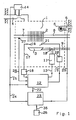
- a water heating system for example a circulation water heating system, comprises a water heater, generally designated 1, with a burner 3, for example a gas burner, which heats a heat exchanger 2 and is supplied with fuel, for example fuel gas, and combustion air.
- a burner for example a gas burner, which heats a heat exchanger 2 and is supplied with fuel, for example fuel gas, and combustion air.
- This burner is independent of the ambient air, i.e. it draws its combustion air from the atmosphere and emits its exhaust gases there.
- the combustion air is supplied from a combustion air duct 4 by means of a fan 5, the exhaust gases of the combustion chamber are discharged by this fan 5 via an exhaust duct 6.
- the flow of the heat exchanger 2 is denoted by 7, the return by 8.
- the fuel supply from a fuel supply line 9 is controlled by a solenoid valve 10, the drive 11 of which is connected via a control line 13 to a general control 12 which also serves to regulate and monitor the operation of the system.
- a general control 12 which also serves to regulate and monitor the operation of the system.
- an air monitor 14 arranged in the combustion air duct 4 for example a pressure can associated with a Venturi tube, connected via a control line 15.
- a burner 3 is assigned a monitoring electrode 16, which is connected to the general control 12 via a control line 17 with a flame measuring amplifier 18 arranged therein.
- a control line 19 extends from the general control 12 to an ignition device 20 and an ignition electrode 21.
- a further control line 22 leads to a circuit 23 according to the invention, into which a control line 24 branches off from the control line 15 and from which a control line 25 for driving the blower 5 extends.
- a clock oscillator 26 is assigned to this circuit 23, which is used for frost protection.
- the system also includes a temperature sensor 27 which is connected to the general control 12 via a control line 28.
- a branch line 30 branches off from the control line 22 at the branching point 29 to the branching point 31, in which a line 32 branches off to the negated input of the OR gate 33.
- the branch Line 30 continues to the input of the AND gate 34, which is fed via an input line 35 from the clock oscillator 26.
- the outputs 36 and 37 of the OR gate 33 and the AND gate 34 are connected to a first counter / comparator 38, specifically the OR gate 33 via a reset input 39.
- the control line 22 branches at the branch point 40 a line 41 to the negated input of a further OR gate 42, which is connected via its other input and via line 43 to a line 44 which leads from the OR gate 33 to a second counter / comparator 45.
- the output of the OR gate 42 is connected to the reset input of a bistable multivibrator (flip-flop) 47, the set input of which is connected via a line 48 to the output of the counter / comparator 38.
- a non-inverted output 49 of this flip-flop 47 connects it to the branch point 51 located on line 50.
- the other inverted output 52 of this flip-flop 47 is connected via a line 53 to the reset input of the second counter / comparator 45.
- a line 55 connects the oscillator 26 to the via a branch point 54 of the line 35 Input of an AND gate 56, which in turn is connected via its output line 57 to the input of the second counter / comparator 45.
- Another AND element 58 arranged in line 22 is connected with its negated input to AND element 56 via line 50 already mentioned above and branch point 51.
- the overflow or underflow of the counters / comparators 38 and 45 is prevented by measures not shown.
- the function of the circuit 23 can also be implemented as a program of a microprocessor and results from its structure in the sense of the invention as follows: If the switch contact of the air monitor 14, for example a pressure socket, remains open as a result of a fault even with sufficient air throughput, the drive of the Blower 5 (and thus burner operation) interrupted for a predetermined period of time, for example for a period of about 15 minutes, but only if the blower 5 was in operation for a predetermined period of time, for example 3 minutes, without feedback from the air watchman 14.
- this shutdown and blocking of the blower and burner operation is ended before the specified minimum duration has expired, if, for example, as a result the completion of a tap, no more heat is requested.
- this prevents excessive cooling of the heat exchanger 2 in the event of a faulty behavior of the air monitor 14, but on the other hand, sporadic errors, for example a mere one-time clamping of a pressure cell, do not permanently block the burner operation.
- the blower 5 is only switched off independently of the level of the outside temperature if this blower has been in operation for a measurable period of time without the air monitor 14 reporting back.
- this switch-off is reversed after a specified period of time or after the heating requirement ceases to exist, for example after a domestic water tap has ended. Then, if there is again a need for heat, another attempt to start the burner operation can take place.
Landscapes
- Engineering & Computer Science (AREA)
- Physics & Mathematics (AREA)
- Thermal Sciences (AREA)
- Chemical & Material Sciences (AREA)
- Combustion & Propulsion (AREA)
- Mechanical Engineering (AREA)
- General Engineering & Computer Science (AREA)
- Regulation And Control Of Combustion (AREA)
- Control Of Combustion (AREA)
- Steam Or Hot-Water Central Heating Systems (AREA)
- Filling Or Discharging Of Gas Storage Vessels (AREA)
- Heat-Pump Type And Storage Water Heaters (AREA)
Abstract
Description
- Die Erfindung betrifft zunächst ein Verfahren zum Schutz einer Wasserheizanlage gegen ein Einfrieren des mit einem raumluftunabhängigen Brenner betriebenen Wasserheizers.
- Bekanntlich erfolgt die Freigabe eines solchen Brenners nur dann, wenn über einen in der Verbrennungsluftführung angeordneten Luftwächter, vorzugsweise eine sogenannte Druckdose, ausreichender Luftdurchsatz gemeldet wird. Bleibt aus irgendwelchen Gründen, zum Beispiel infolge eines Defektes, der Schaltkontakt eines solchen Luftwächters geöffnet, wird der Brennraum weiterhin von Frischluft durchflutet, und dies kann bei niedrigen Außentemperaturen zu einem Einfrieren des Primärwärmetauschers führen.
- Es ist bereits bekannt, das Einfrieren des Wasserheizers einer solchen Wasserheizanlage dadurch zu verhindern, daß der Wasserheizer dann abgeschaltet und verriegelt wird, wenn die Außentemperatur unter einen Mindestwert absinkt und das Gebläse angesteuert wird, ohne daß eine Rückmeldung vom Luftwächter erfolgt.
- Eine solche von der Außentemperatur gesteuerte Abschaltung ist allerdings nur kostenaufwendig zu verwirklichen, zumal sie eines Außentemperaturfühlers bedarf, dessen Installation und Einbindung zusätzlichen Aufwand erfordern.
- Aufgabe der Erfindung ist es, ein Verfahren zu entwickeln, das keines solchen Außentemperaturfühlers bedarf und das sich mit einfachen technischen Mitteln durchführen läßt.
- Erfindungsgemäß wird der Antrieb des Brennergebläses nach Ablauf einer mit der Fehlanzeige des Luftwächters beginnenden, vorgegebenen Zeitspanne auf eine vorgegebene Mindestzeitspanne stillgesetzt.
- Dieses Verfahren erübrigt demnach ein Erfassen der jeweiligen Ist-Außentemperatur und gewährleistet überdies, daß sporadisch auftretende Fehler des Luftwächters, zum Beispiel das Klemmen einer Druckdose, nicht zu einer dauernden Blockierung des Brennerbetriebes führen.
- Im Zusammenhang mit diesem Verfahren erstreckt sich die Erfindung auch auf eine zu dessen Durchführung geeignete Wasserheizanlage, bestehend aus einem Wasserheizer mit einem über ein Gebläse mit Verbrennungsluft gespeisten, einen Wärmetauscher beheizenden Gebläsebrenner, vorzugsweise einem Gasbrenner, sowie einem in der Verbrennungsluftführung angeordneten, vorzugsweise druckempfindlichen Luftwächter, zum Beispiel einer Druckdose, und einer allgemeinen, die Versorgung des Brenners mit Brennstoff und Verbrennungsluft steuernden, unter anderem mit dem Luftwächter und dem Gebläseantrieb über Steuerleitungen verbundenen Steuerung.
- Erfindungsgemäß ist in einer vom Luftwächter zum Antrieb des Gebläses führenden Steuerleitung eine mit der allgemeinen Steuerung über eine Steuerleitung verbundene, an einen Taktoszillator angeschlossene Schaltung mit Zeitgliedern zur Einhaltung der oben genannten beiden Zeitspannen vorgesehen. Eine solche Schaltung kann - nach einer bevorzugten Ausführungsform - zwei über einen bistabilen Multivibrator (Flip-Flop) sowie UND- und ODER-Glieder miteinander verknüpfte Zähler/Vergleicher enthalten.
- Ein Ausführungsbeispiel des Erfindungsgegenstandes ist in den Zeichnungen veranschaulicht, und zwar zeigt
- Figur 1 das Schema einer Wasserheizanlage und
- Figur 2 das Schaubild einer erfindungsgemäßen Schaltung.
- Gemäß Figur 1 umfaßt eine Wasserheizanlage, zum Beispiel eine Umlauf-Wasserheizanlage, einen allgemein mit 1 bezeichneten Wasserheizer mit einem einen Wärmetauscher 2 beheizenden, mit Brennstoff, zum Beispiel Brenngas, und Verbrennungsluft gespeisten Brenner 3, zum Beispiel einem Gasbrenner. Dieser Brenner ist raumluftunabhängig, das heißt bezieht seine Verbrennungsluft aus der Atmosphäre und gibt seine Abgase dorthin ab.
- Die Zufuhr der Verbrennungsluft aus einer Verbrennungsluftführung 4 erfolgt mittels eines Gebläses 5, die Abgase des Brennraumes werden von diesem Gebläse 5 über eine Abgasführung 6 abgeführt.
- Der Vorlauf des Wärmetauschers 2 ist mit 7 bezeichnet, der Rücklauf mit 8.
- Die Brennstoffzufuhr aus einer Brennstoffzufuhrleitung 9 wird von einem Magnetventil 10 gesteuert, dessen Antrieb 11 über eine Steuerleitung 13 mit einer allgemeinen Steuerung 12 verbunden ist, die auch der Regelung und Überwachung des Betriebes der Anlage dient. Mit dieser allgemeinen Steuerung 12 ist zu diesem Zweck ein in der Verbrennungsluftführung 4 angeordneter Luftwächer 14, zum Beispiel eine einem Venturirohr zugeordnete Druckdose, über eine Steuerleitung 15 verbunden.
- Dem Brenner 3 ist eine Überwachungselektrode 16 zugeordnet, die über eine Steuerleitung 17 mit einem darin angeordneten Flammenmeßverstärker 18 mit der allgemeinen Steuerung 12 verbunden ist.
- Ferner erstreckt sich eine Steuerleitung 19 von der allgemeinen Steuerung 12 zu einer Zündeinrichtung 20 und einer Zündelektrode 21.
- Schließlich führt noch eine weitere Steuerleitung 22 zu einer erfindungsgemäßen Schaltung 23, in die auch eine von der Steuerleitung 15 abzweigende Steuerleitung 24 mündet und von der eine Steuerleitung 25 zum Antrieb des Gebläses 5 ausgeht. Dieser Schaltung 23, die dem Frostschutz dient, ist ein Taktoszillator 26 zugeordnet.
- Zur Überwachung der Vorlauftemperatur des Heizwassers umfaßt die Anlage auch noch einen Temperaturfühler 27, der mit der allgemeinen Steuerung 12 über eine Steuerleitung 28 verbunden ist.
- Der Aufbau der erfindungsgemäßen Schaltung 23 ist aus Figur 2 ersichtlich. Von der Steuerleitung 22 zweigt zunächst im Verzweigungspunkt 29 eine Zweigleitung 30 zum Verzweigungspunkt 31 ab, in dem eine Leitung 32 zum negierten Eingang des ODER-Gliedes 33 abzweigt. Die Zweig leitung 30 führt weiter zum Eingang des UND-Gliedes 34, das über eine Eingangsleitung 35 vom Taktoszillator 26 gespeist wird. Das ODER-Glied 33 und das UND-Glied 34 sind mit ihren Ausgängen 36 beziehungsweise 37 an einen ersten Zähler/Vergleicher 38 angeschlossen, und zwar das ODER-Glied 33 über einen Rücksetz-Eingang 39. Ferner zweigt von der Steuerleitung 22 im Verzweigungspunkt 40 eine Leitung 41 zum negierten Eingang eines weiteren ODER-Gliedes 42 ab, das über seinen anderen Eingang und über die Leitung 43 mit einer Leitung 44 verbunden ist, die vom ODER-Glied 33 zu einem zweiten Zähler/Vergleicher 45 führt.
- Der Ausgang des ODER-Gliedes 42 ist mit dem Rücksetz-Eingang eines bistabilen Multivibrators (Flip-Flops) 47 verbunden, dessen Setz-Eingang über eine Leitung 48 mit dem Ausgang des Zählers/Vergleichers 38 verbunden ist.
- Ein nicht invertierter Ausgang 49 dieses Flip-Flops 47 verbindet ihn mit dem in der Leitung 50 gelegenen Verzweigungspunkt 51. Der andere invertierte Ausgang 52 dieses Flip-Flops 47 ist über eine Leitung 53 mit dem Rücksetz-Eingang des zweiten Zählers/Vergleichers 45 verbunden.
- Schließlich verbindet eine Leitung 55 den Oszillator 26 über einen Verzweigungspunkt 54 der Leitung 35 mit dem Eingang eines UND-Gliedes 56, das seinerseits über seine Ausgangsleitung 57 mit dem Eingang des zweiten Zählers/Vergleichers 45 verbunden ist.
- Ein weiteres in der Leitung 22 angeordnetes UND-Glied 58 ist mit seinem negierten Eingang über die bereits oben erwähnte Leitung 50 und den Verzweigungspunkt 51 mit dem UND-Glied 56 verbunden.
- Das Über- oder Unterlaufen der Zähler/Vergleicher 38 und 45 wird durch nicht dargestellte Maßnahmen verhindert. Die Funktion der Schaltung 23 ist auch als Programm eines Mikroprozessors realisierbar und ergibt sich aus deren Aufbau im Sinne der Erfindung wie folgt: Bleibt der Schaltkontakt des Luftwächters 14, zum Beispiel einer Druckdose, infolge eines Fehlers auch bei ausreichendem Luftdurchsatz offen, wird der Antrieb des Gebläses 5 (und damit auch der Brennerbetrieb) auf eine vorbestimmte Zeitspanne, zum Beispiel auf eine Dauer von etwa 15 Minuten, unterbrochen, jedoch nur dann, wenn das Gebläse 5 über eine vorgegebene Zeitspanne von beispielsweise 3 Minuten in Betrieb war, ohne daß eine Rückmeldung vom Luftwächter 14 erfolgte.
- Diese Abschaltung und Blockierung des Gebläse- und Brennerbetriebes wird allerdings noch vor Ablauf der vorgegebenen Mindestdauer beendet, sofern, zum Beispiel infolge der Beendigung einer Brauchwasserzapfung, keine Wärme mehr angefordert wird.
Dadurch wird einerseits bei einem Fehlverhalten des Luftwächters 14 eine zu weit gehende Abkühlung des Wärmetauschers 2 vermieden, andererseits verursachen aber sporadisch auftretende Fehler, zum Beispiel ein bloß einmaliges Klemmen einer Druckdose, keine dauernde Blockierung des Brennerbetriebes.
Demnach erfolgt beim erfindungsgemäßen Verfahren eine von der Höhe der Außentemperatur unabhängige Abschaltung des Gebläses 5 nur dann, wenn dieses Gebläse über eine bemeßbare Zeitspanne in Betrieb war, ohne daß eine Rückmeldung seitens des Luftwächters 14 erfolgte. - Diese Abschaltung wird allerdings nach einer vorgegebenen Zeitspanne oder nach Wegfall des Wärmebedarfes, zum Beispiel nach Beendigung einer Brauchwasserzapfung, rückgängig gemacht. Danach kann, falls abermals ein Wärmebedarf vorliegt, neuerlich ein Versuch zum Starten des Brennerbetriebes stattfinden.
Claims (5)
Applications Claiming Priority (2)
| Application Number | Priority Date | Filing Date | Title |
|---|---|---|---|
| AT1440/89 | 1989-06-13 | ||
| AT0144089A AT397572B (de) | 1989-06-13 | 1989-06-13 | Verfahren zum schutz einer wasserheizanlage gegen ein einfrieren, wasserheizanlage zu dessen durchführung sowie schaltung für eine solche wasserheizanlage |
Publications (3)
| Publication Number | Publication Date |
|---|---|
| EP0403422A2 true EP0403422A2 (de) | 1990-12-19 |
| EP0403422A3 EP0403422A3 (de) | 1991-04-17 |
| EP0403422B1 EP0403422B1 (de) | 1994-03-30 |
Family
ID=3513934
Family Applications (1)
| Application Number | Title | Priority Date | Filing Date |
|---|---|---|---|
| EP90710014A Expired - Lifetime EP0403422B1 (de) | 1989-06-13 | 1990-06-13 | Verfahren zum Schutz einer Wasserheizanlage gegen ein Einfrieren und Wasserheizanlage zu dessen Durchführung |
Country Status (3)
| Country | Link |
|---|---|
| EP (1) | EP0403422B1 (de) |
| AT (2) | AT397572B (de) |
| DE (2) | DE59005155D1 (de) |
Cited By (1)
| Publication number | Priority date | Publication date | Assignee | Title |
|---|---|---|---|---|
| US6368556B1 (en) | 1994-06-28 | 2002-04-09 | Akeda Dental A/S | Apparatus for operational cleaning of dental handpieces |
Family Cites Families (3)
| Publication number | Priority date | Publication date | Assignee | Title |
|---|---|---|---|---|
| SU1038743A2 (ru) * | 1982-03-17 | 1983-08-30 | Предприятие П/Я А-7080 | Устройство автоматической защиты калорифера от замораживани |
| JPS59167646A (ja) * | 1983-03-14 | 1984-09-21 | Sanyo Electric Co Ltd | 温水ボイラの制御装置 |
| SU1180653A1 (ru) * | 1984-04-23 | 1985-09-23 | Предприятие П/Я В-2616 | Система регулировани и защиты от замораживани калорифера приточно-вентил ционной установки |
-
1989
- 1989-06-13 AT AT0144089A patent/AT397572B/de not_active IP Right Cessation
-
1990
- 1990-06-13 DE DE90710014T patent/DE59005155D1/de not_active Expired - Fee Related
- 1990-06-13 AT AT90710014T patent/ATE103698T1/de not_active IP Right Cessation
- 1990-06-13 EP EP90710014A patent/EP0403422B1/de not_active Expired - Lifetime
- 1990-06-13 DE DE4018985A patent/DE4018985A1/de not_active Withdrawn
Cited By (1)
| Publication number | Priority date | Publication date | Assignee | Title |
|---|---|---|---|---|
| US6368556B1 (en) | 1994-06-28 | 2002-04-09 | Akeda Dental A/S | Apparatus for operational cleaning of dental handpieces |
Also Published As
| Publication number | Publication date |
|---|---|
| EP0403422A3 (de) | 1991-04-17 |
| DE4018985A1 (de) | 1990-12-20 |
| DE59005155D1 (de) | 1994-05-05 |
| AT397572B (de) | 1994-05-25 |
| ATA144089A (de) | 1993-09-15 |
| ATE103698T1 (de) | 1994-04-15 |
| EP0403422B1 (de) | 1994-03-30 |
Similar Documents
| Publication | Publication Date | Title |
|---|---|---|
| DE69506475T2 (de) | Steuerungsverfahren für eine Eiserzeugungsmaschine und Gerät dafür | |
| DE69027350T2 (de) | Kontrollverfahren für Kraftstoffbrenner mit heisser Oberflächenzündung | |
| EP4015904A1 (de) | Verfahren und vorrichtung zum schutz eines heizgerätes beim zünden eines gemisches aus luft und wasserstoffhaltigem brenngas | |
| DE19903305C5 (de) | Verfahren zur Flammüberwachung in einem Fahrzeugheizgerät | |
| DE2700921A1 (de) | Vereisungsdetektor | |
| EP0403422B1 (de) | Verfahren zum Schutz einer Wasserheizanlage gegen ein Einfrieren und Wasserheizanlage zu dessen Durchführung | |
| DE3020228C2 (de) | Sicherheitseinrichtung für brennstoffbeheizte Geräte | |
| DE3339429A1 (de) | Einrichtung zur reduzierung von abgas-schadstoffen | |
| DE1551950B2 (de) | Schaltungsanordnung zur programmsteuerung einer feuerungs anlage | |
| EP0676682B1 (de) | Solarkollektor mit Störungsüberwachung | |
| EP0398011B1 (de) | Steuergerät-Kühlsystem für eine Brennkraftmaschine | |
| DE69110214T2 (de) | Steuerungsverfahren für Brenner. | |
| DE4433387A1 (de) | Steuerung | |
| DE2138869A1 (de) | Überwachungseinrichtung für einen Verbrennungsregler | |
| DE4142841C2 (de) | Verfahren zum Starten der Verbrennung eines Brennstoff-Luft-Gemisches in einem Brennraum und Vorrichtung zur Durchführung dieses Verfahrens | |
| EP4089329B1 (de) | Verfahren und vorrichtung zum sicheren wiederstart eines mit hohem wasserstoffanteil betriebenen brenners | |
| EP1039227B1 (de) | Verfahren zur Erkennung und Beurteilung von Zündproblemen | |
| EP1039226A2 (de) | Zündeinheit ohne Zündflamme | |
| EP0315055B1 (de) | Verfahren zum Überprüfen eines Gasventils und Vorrichtung zur Durchführung des Verfahrens | |
| DE4038925C2 (de) | ||
| AT412419B (de) | Verfahren und eine vorrichtung zur überprüfung der zündfunktion einer zündeinrichtung | |
| EP1645803B1 (de) | Verfahren zum Starten eines Heizgerätes, insbesondere Fahrzeugheizgerätes | |
| EP0315054B1 (de) | Verfahren zum Überwachen eines einen Mikroprozessor überwachenden Watchdog-Timers und Vorrichtung zur Durchführung des Verfahrens | |
| CH658117A5 (en) | Method of testing the monitoring members of a steam boiler and arrangement for implementing the method | |
| CH682011A5 (de) |
Legal Events
| Date | Code | Title | Description |
|---|---|---|---|
| PUAI | Public reference made under article 153(3) epc to a published international application that has entered the european phase |
Free format text: ORIGINAL CODE: 0009012 |
|
| AK | Designated contracting states |
Kind code of ref document: A2 Designated state(s): AT BE CH DE DK ES FR GB GR IT LI LU NL SE |
|
| PUAL | Search report despatched |
Free format text: ORIGINAL CODE: 0009013 |
|
| AK | Designated contracting states |
Kind code of ref document: A3 Designated state(s): AT BE CH DE DK ES FR GB GR IT LI LU NL SE |
|
| 17P | Request for examination filed |
Effective date: 19910318 |
|
| 17Q | First examination report despatched |
Effective date: 19911118 |
|
| RAP1 | Party data changed (applicant data changed or rights of an application transferred) |
Owner name: N.V. VAILLANT S.A. Owner name: VAILLANT S.A.R.L Owner name: VAILLANT GES.M.B.H Owner name: VAILLANT LTD. Owner name: JOH. VAILLANT GMBH U. CO. Owner name: VAILLANT B.V. Owner name: VAILLANT GMBH |
|
| GRAA | (expected) grant |
Free format text: ORIGINAL CODE: 0009210 |
|
| AK | Designated contracting states |
Kind code of ref document: B1 Designated state(s): AT BE CH DE DK ES FR GB GR IT LI LU NL SE |
|
| PG25 | Lapsed in a contracting state [announced via postgrant information from national office to epo] |
Ref country code: BE Effective date: 19940330 Ref country code: ES Free format text: THE PATENT HAS BEEN ANNULLED BY A DECISION OF A NATIONAL AUTHORITY Effective date: 19940330 Ref country code: NL Effective date: 19940330 Ref country code: DK Effective date: 19940330 Ref country code: GB Effective date: 19940330 Ref country code: FR Effective date: 19940330 Ref country code: SE Free format text: THE PATENT HAS BEEN ANNULLED BY A DECISION OF A NATIONAL AUTHORITY Effective date: 19940330 Ref country code: GR Free format text: LAPSE BECAUSE OF FAILURE TO SUBMIT A TRANSLATION OF THE DESCRIPTION OR TO PAY THE FEE WITHIN THE PRESCRIBED TIME-LIMIT Effective date: 19940330 |
|
| REF | Corresponds to: |
Ref document number: 103698 Country of ref document: AT Date of ref document: 19940415 Kind code of ref document: T |
|
| ITF | It: translation for a ep patent filed | ||
| REF | Corresponds to: |
Ref document number: 59005155 Country of ref document: DE Date of ref document: 19940505 |
|
| PG25 | Lapsed in a contracting state [announced via postgrant information from national office to epo] |
Ref country code: LU Free format text: LAPSE BECAUSE OF NON-PAYMENT OF DUE FEES Effective date: 19940630 |
|
| EN | Fr: translation not filed | ||
| NLV1 | Nl: lapsed or annulled due to failure to fulfill the requirements of art. 29p and 29m of the patents act | ||
| GBV | Gb: ep patent (uk) treated as always having been void in accordance with gb section 77(7)/1977 [no translation filed] |
Effective date: 19940330 |
|
| PLBE | No opposition filed within time limit |
Free format text: ORIGINAL CODE: 0009261 |
|
| STAA | Information on the status of an ep patent application or granted ep patent |
Free format text: STATUS: NO OPPOSITION FILED WITHIN TIME LIMIT |
|
| 26N | No opposition filed | ||
| PG25 | Lapsed in a contracting state [announced via postgrant information from national office to epo] |
Ref country code: IT Free format text: LAPSE BECAUSE OF NON-PAYMENT OF DUE FEES;WARNING: LAPSES OF ITALIAN PATENTS WITH EFFECTIVE DATE BEFORE 2007 MAY HAVE OCCURRED AT ANY TIME BEFORE 2007. THE CORRECT EFFECTIVE DATE MAY BE DIFFERENT FROM THE ONE RECORDED. Effective date: 20050613 |
|
| PGFP | Annual fee paid to national office [announced via postgrant information from national office to epo] |
Ref country code: CH Payment date: 20080606 Year of fee payment: 19 |
|
| PGFP | Annual fee paid to national office [announced via postgrant information from national office to epo] |
Ref country code: AT Payment date: 20080520 Year of fee payment: 19 |
|
| PGFP | Annual fee paid to national office [announced via postgrant information from national office to epo] |
Ref country code: DE Payment date: 20080515 Year of fee payment: 19 |
|
| REG | Reference to a national code |
Ref country code: CH Ref legal event code: PL |
|
| PG25 | Lapsed in a contracting state [announced via postgrant information from national office to epo] |
Ref country code: CH Free format text: LAPSE BECAUSE OF NON-PAYMENT OF DUE FEES Effective date: 20090630 Ref country code: LI Free format text: LAPSE BECAUSE OF NON-PAYMENT OF DUE FEES Effective date: 20090630 |
|
| PG25 | Lapsed in a contracting state [announced via postgrant information from national office to epo] |
Ref country code: DE Free format text: LAPSE BECAUSE OF NON-PAYMENT OF DUE FEES Effective date: 20100101 Ref country code: AT Free format text: LAPSE BECAUSE OF NON-PAYMENT OF DUE FEES Effective date: 20090613 |