EP0403364A2 - Bidirektionale Datenübertragungsanordnung zum Datenaustausch zwischen einer Zentralstation und lokalen Stationen - Google Patents
Bidirektionale Datenübertragungsanordnung zum Datenaustausch zwischen einer Zentralstation und lokalen Stationen Download PDFInfo
- Publication number
- EP0403364A2 EP0403364A2 EP90401614A EP90401614A EP0403364A2 EP 0403364 A2 EP0403364 A2 EP 0403364A2 EP 90401614 A EP90401614 A EP 90401614A EP 90401614 A EP90401614 A EP 90401614A EP 0403364 A2 EP0403364 A2 EP 0403364A2
- Authority
- EP
- European Patent Office
- Prior art keywords
- line
- station
- data
- local
- central station
- Prior art date
- Legal status (The legal status is an assumption and is not a legal conclusion. Google has not performed a legal analysis and makes no representation as to the accuracy of the status listed.)
- Ceased
Links
Images

Classifications
-
- H—ELECTRICITY
- H04—ELECTRIC COMMUNICATION TECHNIQUE
- H04L—TRANSMISSION OF DIGITAL INFORMATION, e.g. TELEGRAPHIC COMMUNICATION
- H04L12/00—Data switching networks
- H04L12/28—Data switching networks characterised by path configuration, e.g. LAN [Local Area Networks] or WAN [Wide Area Networks]
- H04L12/42—Loop networks
- H04L12/427—Loop networks with decentralised control
- H04L12/43—Loop networks with decentralised control with synchronous transmission, e.g. time division multiplex [TDM], slotted rings
Definitions
- the present invention relates generally to digital data transmission networks on a physical link, and more particularly relates to a method for transferring digital data from a central station to a set of local stations, and vice versa, as well as a device for the simultaneous bidirectional transfer of digital data between at least two stations, allowing the implementation of the method.
- the invention applies in particular, but not exclusively, to an industrial field network, in which the central station is an equipment for controlling and regulating an industrial process, and the local stations are sensors and actuators involved in the industrial process.
- the stations have appropriate interfaces to be able to exchange data on the line.
- access to the network is generally carried out under the control or arbitration of the central station.
- the central station and a local station wish to exchange data, on the initiative of one or the other, they inform each other by appropriate dialogue protocols, then one or more frames are transmitted on the line during a reserved time interval. Other data transfers may occur after the line has been released.
- the first object of the present is to overcome these drawbacks of the prior art and to propose a data exchange method which allows a data exchange simultaneously in both directions, in a way considerably simplified and in particular without using complex protocols to carry out these transfers.
- the present invention relates first of all to a method of transferring digital data from a central station to a set of local stations, and vice versa, the local stations being provided in succession on a loop line starting from the central station. and returning to it, characterized in that it comprises the stages according to which: the central station transmits on the line a first sub-frame including an ordered set of data intended for the local stations, and each local station receiving a subframe extracts from it the data which is intended for it, recognized by its position in the frame, substitutes for it another data intended for the central station, and retransmits the new subframe thus formed to the next station on the loop, the last local station thus retransmitting to the central station a last sub-frame including an ordered set of data originating from said local stations.
- the present invention also aims to simplify the physical link of a data exchange network, allowing in particular the implementation of the above method, in particular allowing a bidirectional link in full duplex on the same pair of shielded conductors connecting two any stations.
- the present invention also relates to a device for the simultaneous bidirectional transfer of digital data between at least two stations via at least one line segment consisting of a pair of screened conductors, characterized in that: - at each end of line segment terminating at a station is associated a line coupler; - each line coupler includes: . two analog terminals connected to the two conductors of the associated segment, and a logic input and a logic output connected to the station, . an electric generator having an electromotive force whose value depends on the value of the signal present on its logic input and an internal resistance substantially equal to the characteristic impedance of the associated line segment, and .
- Such a device is advantageous in that it allows, for example, the implementation of the process described above without requiring a loop mounting of the line, the various stations being simply provided one after the other, with the only link physical line segment consisting of a pair of shielded conductors between two adjacent stations.
- the central station and the local stations communicate with each other via appropriate interfaces and a physical link.
- the local station comprises a network coupler, denoted CPR, while each local station comprises a junction box, respectively BJo to BJ P-1 .
- the user assigns an identifier i K of between 0 and 63, the identifiers i0 to i P-1 being all different in pairs.
- any identifier i is assigned two so-called central variables, each in the form of a 16-bit word, namely a transmitted word, noted ei , and a received word noted ri .
- the two groups of 64 words physically constitute two memories, denoted respectively E and R, in the network coupler CPR.
- the user can write data to memory E and read data from memory R.
- each junction box two so-called local variables are associated with the identifier i considered, each in the form of a 16-bit word, namely an transmitted word denoted ⁇ i and a received word denoted ⁇ i . These words physically constitute two registers located in the junction box considered.
- the user of the junction box can write the word ⁇ i in the associated register and read the word ⁇ i from the associated register.
- the essential function of the network according to the invention is for any identifier i actually assigned to a junction box, to transfer ⁇ i in ri and to transfer ei in ⁇ i , which allows exchanges of information from the central station to each local station and reciprocally.
- the above information transfers are carried out by circulation of frames on the loop of FIG. 1, in a determined direction.
- Each frame is broken down, according to the segment of the link where we are placed, into P + 1 different subframes, denoted S0 to S P , corresponding respectively to the segments m0 to m P.
- Each subframe S K conveys digital data D K consisting of an ordered sequence of 64 words of 16 bits, denoted d (0, K) to d (63, K).
- the role of the junction box BJ K is therefore to receive the subframe S K , to extract the word ei whose rank in the received subframe S K is determined by the value of the identifier i K considered, to memorize it in the corresponding register, to form the new frame S K + 1 by replacing ei by ⁇ i , read in the other register of the box, and to emit this new frame.
- this ensures, by circulation of the frame, all of the data transfers from ⁇ i to ri and from ei to ⁇ i , for all the i allocated to a junction box, and therefore for all junction boxes.
- each subframe contains 8 16-bit words.
- the data received e6 (data sent by the network coupler), contained in the sub-frame S0, is stored in the corresponding register ⁇ 6 , while the data sent ⁇ 6 is read in the register with the same name and it is substituted for the word e6 in the sub-frame S0, to form the sub-frame S1.
- the word e2 of the subframe S1 is replaced by the word ⁇ 2 to form the subframe S2, and so on.
- the words e1 , e5 and e7 are present but remain unchanged. They demonstrate the availability of the network to add three additional junction boxes without modification and ensure the transfer of words between them and the network coupler.
- Another advantage of the data exchange method according to the invention lies in the fact that, during the circulation of each frame in the network, the transfer of data from the central station to each local station is simultaneously ensured and the transfer another data from each local station to the central station. As a result, it is not necessary to use special exchange protocols, depending on whether the local station is data generator (sensor type station) or data receiver (actuator type station), or the of them.
- the organization of the circulation of frames on the network in its temporal aspect, will be done in a way simple, at a regular rate, under the control of the central station.
- the sub-frames of the same frame are transmitted by each station in synchronism, to the nearest propagation times.
- the encoding or modulation of the digital information to be conveyed on the network will use conventional techniques.
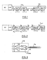
- FIG. 2 shows a network in which there is no return segment m P properly speaking.
- each segment m K is bidirectional and allows on the one hand the circulation of the subframe SK to the next junction box, and on the other hand the circulation of the final subframe SP towards the network coupler .
- each junction box is able on the one hand to modify the subframe received from the previous junction box and to send the new subframe to the next junction box, and on the other hand to transfer without modification of the final subframe received from the next junction box to the previous junction box.
- the physical link used is a shielded pair of conductors, for example twisted, whose impedance is denoted Z and whose weakening is denoted A (in nepers).
- the different line segments m0 to m P-1 are connected to the network coupler CPR and to the various junction boxes by devices called line couplers, denoted CM.
- the line couplers are represented by conventional diagrams in which: x designates a two-state logic input terminal, y designates a two-state logical echo terminal, a and b designate two analog terminals, intended for connection with the line.
- a line coupler behaves like an electric generator, characterized by its electromotive force e and its internal impedance R.
- R is chosen equal to Z.
- the logic echo signal y depends, as will be seen later, on both the logic input signal x and the analog output voltage u (between terminals a and b) of the line coupler.
- the logic signals x and y are galvanically separated from the analog terminals a and b, by any suitable means such as transformer or opto-coupler.
- FIG. 5 illustrates the connection by a line segment m K + 1 between two line couplers, respectively CM ′ and CM ⁇ , belonging respectively to the junction boxes BJ K and BJ K + 1 .
- These line couplers respectively have terminals x ′, y ′, a ′, b ′ and x ⁇ , y ⁇ , a ⁇ , b ⁇ .
- FIG. 3 schematically illustrates the internal structure of the CPR network coupler. It contains a single line coupler CM CPR whose analog terminals a and b are connected to the pair of conductors of the segment m0.
- the logic input x is connected to the emitted frame memory E, mentioned above, by means of an enc encoder, while the logic output y is connected to the frame memory R received via a decoder dec .
- the central station SC (FIG. 2) accesses memories E and R as it wishes, in write and read respectively.
- FIG. 4 schematically represents the internal structure of a junction box BJ K.
- CM K and CM K ′ each line couplers CM K and CM K ′, having terminals a, b, x, y and a ′, b ′, x ′, y ′ respectively.
- the terminals a, b of the first coupler CM K are connected to the two conductors of the segment m K , while the terminals a ′, b ′ of the second coupler CM K ′ are connected to the two conductors of the following segment m K + 1 .
- the terminals y ′ and x are connected together.
- the logic output there is connected to a processor P K , containing the received word registers and the transmitted word registers, respectively M R and M E , via a decoder denoted decK , while the processor is connected to the logic input x ′ Via an encoder noted encK .
- the processor P K is responsible for extracting from the datum D K conveyed by the subframe S K the datum ei considered, for writing this datum in M R , for reading the datum ⁇ i to be transmitted in M E , and for replacing ei by ⁇ i in the data D K , which forms the data D K + 1 corresponding to the following sub-frame S K + 1 .
- the terminals a ′ and b ′ are not connected.
- the coupler CM P-1 ′ receiving the subframe SP on its input x ′ will deliver this same subframe on its output y ′, and the subframe SP will thus be conveyed back to the network coupler via the network coupler CM P-1 , the segment m P-1 and the other junction boxes and segments (see Figure 2), finally reaching the line coupler located in the network coupler CPR.
- FIG. 6 corresponds to the block illustration of FIG. 5.
- two line couplers CM ′ and CM ⁇ belonging for example to two adjacent junction boxes are modeled by generators (e ′, R ′) and (e ⁇ , R ⁇ ) as described above.
- the voltage e ′ (t) is known, because "manufactured" as a function of the logic value x ′.
- u ′ (t) can be known by an appropriate voltage measurement in the line coupler CM ′.
- the logic input x ⁇ of the line coupler CM ⁇ determines the value of the electromotive force e ⁇ of the modeling generator, according to the law (1) set out above; then, by comparing the difference in voltages 2u ′ - e ′ in the line coupler CM ′ with the threshold values - ⁇ E and + ⁇ E (law (2)), the binary value taken is reproduced on the logic output y ′ by x ⁇ , to the nearest propagation time.
- junction box located at the end of the line opposite the network coupler acts as a mirror for the signals of the line, without it being necessary to bring it there. any physical modification.
Landscapes
- Engineering & Computer Science (AREA)
- Computer Networks & Wireless Communication (AREA)
- Signal Processing (AREA)
- Small-Scale Networks (AREA)
- Bidirectional Digital Transmission (AREA)
Applications Claiming Priority (2)
| Application Number | Priority Date | Filing Date | Title |
|---|---|---|---|
| FR8907778 | 1989-06-13 | ||
| FR8907778A FR2648296B1 (fr) | 1989-06-13 | 1989-06-13 | Procede d'echange de donnees entre une station centrale et des stations locales et dispositif de transfert bidirectionnel de donnees pour la mise en oeuvre du procede |
Publications (2)
| Publication Number | Publication Date |
|---|---|
| EP0403364A2 true EP0403364A2 (de) | 1990-12-19 |
| EP0403364A3 EP0403364A3 (de) | 1991-04-03 |
Family
ID=9382641
Family Applications (1)
| Application Number | Title | Priority Date | Filing Date |
|---|---|---|---|
| EP19900401614 Ceased EP0403364A3 (de) | 1989-06-13 | 1990-06-12 | Bidirektionale Datenübertragungsanordnung zum Datenaustausch zwischen einer Zentralstation und lokalen Stationen |
Country Status (2)
| Country | Link |
|---|---|
| EP (1) | EP0403364A3 (de) |
| FR (1) | FR2648296B1 (de) |
Cited By (2)
| Publication number | Priority date | Publication date | Assignee | Title |
|---|---|---|---|---|
| WO1996037985A1 (en) * | 1995-05-24 | 1996-11-28 | Thomson Consumer Electronics, Inc. | A ring bus data transfer system |
| US6072804A (en) * | 1995-05-24 | 2000-06-06 | Thomson Consumer Electronics, Inc. | Ring bus data transfer system |
Family Cites Families (2)
| Publication number | Priority date | Publication date | Assignee | Title |
|---|---|---|---|---|
| FR2315725A1 (fr) * | 1975-06-27 | 1977-01-21 | Radiotechnique Compelec | Procede d'exploitation de donnees dans un reseau a configuration en boucle, et reseau pour la mise en oeuvre du procede |
| JPH0671270B2 (ja) * | 1982-01-26 | 1994-09-07 | 株式会社日立製作所 | データ伝送ネットワーク |
-
1989
- 1989-06-13 FR FR8907778A patent/FR2648296B1/fr not_active Expired - Fee Related
-
1990
- 1990-06-12 EP EP19900401614 patent/EP0403364A3/de not_active Ceased
Cited By (2)
| Publication number | Priority date | Publication date | Assignee | Title |
|---|---|---|---|---|
| WO1996037985A1 (en) * | 1995-05-24 | 1996-11-28 | Thomson Consumer Electronics, Inc. | A ring bus data transfer system |
| US6072804A (en) * | 1995-05-24 | 2000-06-06 | Thomson Consumer Electronics, Inc. | Ring bus data transfer system |
Also Published As
| Publication number | Publication date |
|---|---|
| EP0403364A3 (de) | 1991-04-03 |
| FR2648296A1 (fr) | 1990-12-14 |
| FR2648296B1 (fr) | 1994-02-18 |
Similar Documents
| Publication | Publication Date | Title |
|---|---|---|
| EP1701273B1 (de) | Global asynchrone Kommunikationsarchitektur für ein System auf einem integrierten Schaltkreis | |
| EP0005722A1 (de) | Auswahlsystem für Vorrangsschnittstellen | |
| FR2486739A1 (fr) | Systeme de transmission en boucle muni d'un agencement d'acheminement de messages par contournement | |
| FR2779843A1 (fr) | Composant memoire multiport serie et application a un ordinateur | |
| FR2643476A1 (fr) | Procede de transfert de donnees dans un systeme informatique, et bus pour la mise en oeuvre de ce procede | |
| EP0755010A1 (de) | Schnittstelleneinrichtung zwischen einem Rechner redundanter Architektur und einem Kommunikationsmittel | |
| EP0166838B1 (de) | Verfahren und Anordnung zur Detektion einer besonderen Bitkonfiguration in einem seriellen Bitstrom | |
| EP0752669B1 (de) | Vorrichtung zur Datenübertragung zwischen einer Mehrzahl von Funktionsmodulen in einer lokalen Buseinheit und einem externen ARINC-629-Bus | |
| FR2765706A1 (fr) | Lecteur de cartes a puces a protocole de transmission rapide | |
| EP0340841A1 (de) | Koppelpunktschaltungselement zwischen zwei Daten-Sammelleitungen | |
| EP0704952B2 (de) | Selbstüberwachungssystem, insbesondere für elektrische Vorrichtung, vorzugsweise für einen Hochspannungs-SF6-Leistungsschalter | |
| EP0403364A2 (de) | Bidirektionale Datenübertragungsanordnung zum Datenaustausch zwischen einer Zentralstation und lokalen Stationen | |
| FR2493562A1 (fr) | Systeme d'utilisation de disques en commun et d'intercommunication entre disques | |
| EP0683620A1 (de) | Verfahren und Vorrichtung zur Übertragung von asynchrone Daten auf einem synchronen Bus | |
| FR2765425A1 (fr) | Procede de detection d'erreurs sur une liaison serie d'un circuit integre et dispositif de mise en oeuvre du procede | |
| EP0895159B1 (de) | Verfahren zur Entleeren von Hochdurchsatzübertragungspuffern und Vorrichtung zur Ausführung des Verfahrens | |
| EP0974902B1 (de) | Verfahren um Fehler auf einer seriellen Verbindung einer integrierten Schaltung zu erkennen und Vorrichtung zur Durchführung des Verfahrens | |
| EP0376384A1 (de) | Informationsübermittlungseinrichtung unter Verwendung von statistischer Kodierung, Sende- und Empfangsteil für eine solche Anordnung | |
| EP0792071B1 (de) | MPEG2-Dekodierer | |
| FR2865292A1 (fr) | Procede d'arbitrage hierarchise | |
| FR2850508A1 (fr) | Procede d'insertion et de traitement d'informations pour le controle par un noeud de la diffusion d'un flux de donnees traversant un reseau de base d'un reseau heterogene, et noeuds correspondants | |
| FR2710804A1 (fr) | Dispositif numérique de connexion d'une pluralité de stations de travail sur un réseau local en anneau. | |
| EP1044541B1 (de) | Router zur wegeleitung von datenpaketen | |
| FR2526975A1 (fr) | Procede pour gerer l'echange d'informations entre plusieurs unites interconnectees entre elles par un support de transmission, et systeme pour la mise en oeuvre du procede | |
| EP0466555A1 (de) | Lokales Netzwerk für Interkommunikation zwischen Datenverarbeitungsmodulen |
Legal Events
| Date | Code | Title | Description |
|---|---|---|---|
| PUAI | Public reference made under article 153(3) epc to a published international application that has entered the european phase |
Free format text: ORIGINAL CODE: 0009012 |
|
| AK | Designated contracting states |
Kind code of ref document: A2 Designated state(s): DE ES GB IT SE |
|
| PUAL | Search report despatched |
Free format text: ORIGINAL CODE: 0009013 |
|
| AK | Designated contracting states |
Kind code of ref document: A3 Designated state(s): DE ES GB IT SE |
|
| 17P | Request for examination filed |
Effective date: 19910610 |
|
| 17Q | First examination report despatched |
Effective date: 19930709 |
|
| STAA | Information on the status of an ep patent application or granted ep patent |
Free format text: STATUS: THE APPLICATION HAS BEEN REFUSED |
|
| 18R | Application refused |
Effective date: 19940714 |