EP0402508B2 - Means for detecting a series of abnormal events in an electrical signal, especially the depolarisation signal of a heart - Google Patents
Means for detecting a series of abnormal events in an electrical signal, especially the depolarisation signal of a heart Download PDFInfo
- Publication number
- EP0402508B2 EP0402508B2 EP89110885A EP89110885A EP0402508B2 EP 0402508 B2 EP0402508 B2 EP 0402508B2 EP 89110885 A EP89110885 A EP 89110885A EP 89110885 A EP89110885 A EP 89110885A EP 0402508 B2 EP0402508 B2 EP 0402508B2
- Authority
- EP
- European Patent Office
- Prior art keywords
- signal
- heart
- events
- event
- characteristic quantity
- Prior art date
- Legal status (The legal status is an assumption and is not a legal conclusion. Google has not performed a legal analysis and makes no representation as to the accuracy of the status listed.)
- Expired - Lifetime
Links
- 230000002159 abnormal effect Effects 0.000 title claims description 45
- 230000028161 membrane depolarization Effects 0.000 claims description 45
- 206010061592 cardiac fibrillation Diseases 0.000 claims description 41
- 230000002600 fibrillogenic effect Effects 0.000 claims description 39
- 230000004064 dysfunction Effects 0.000 claims description 5
- 230000001747 exhibiting effect Effects 0.000 claims 4
- 210000000056 organ Anatomy 0.000 claims 1
- 238000001514 detection method Methods 0.000 description 33
- 239000008186 active pharmaceutical agent Substances 0.000 description 12
- 230000033764 rhythmic process Effects 0.000 description 7
- 206010003119 arrhythmia Diseases 0.000 description 6
- 230000006793 arrhythmia Effects 0.000 description 5
- 230000008859 change Effects 0.000 description 5
- 230000007257 malfunction Effects 0.000 description 5
- 230000000694 effects Effects 0.000 description 3
- 230000008901 benefit Effects 0.000 description 2
- 230000000747 cardiac effect Effects 0.000 description 2
- 238000010586 diagram Methods 0.000 description 2
- 230000010354 integration Effects 0.000 description 2
- 238000000034 method Methods 0.000 description 2
- 230000000630 rising effect Effects 0.000 description 2
- 238000012935 Averaging Methods 0.000 description 1
- 230000015572 biosynthetic process Effects 0.000 description 1
- 239000003990 capacitor Substances 0.000 description 1
- 230000003750 conditioning effect Effects 0.000 description 1
- 239000013078 crystal Substances 0.000 description 1
- 230000006870 function Effects 0.000 description 1
- 230000003993 interaction Effects 0.000 description 1
- 230000010355 oscillation Effects 0.000 description 1
- 238000001556 precipitation Methods 0.000 description 1
- 230000008569 process Effects 0.000 description 1
- 238000009751 slip forming Methods 0.000 description 1
- 230000001225 therapeutic effect Effects 0.000 description 1
Images


Classifications
-
- A—HUMAN NECESSITIES
- A61—MEDICAL OR VETERINARY SCIENCE; HYGIENE
- A61B—DIAGNOSIS; SURGERY; IDENTIFICATION
- A61B5/00—Measuring for diagnostic purposes; Identification of persons
- A61B5/24—Detecting, measuring or recording bioelectric or biomagnetic signals of the body or parts thereof
- A61B5/316—Modalities, i.e. specific diagnostic methods
- A61B5/318—Heart-related electrical modalities, e.g. electrocardiography [ECG]
- A61B5/346—Analysis of electrocardiograms
- A61B5/349—Detecting specific parameters of the electrocardiograph cycle
- A61B5/361—Detecting fibrillation
-
- A—HUMAN NECESSITIES
- A61—MEDICAL OR VETERINARY SCIENCE; HYGIENE
- A61N—ELECTROTHERAPY; MAGNETOTHERAPY; RADIATION THERAPY; ULTRASOUND THERAPY
- A61N1/00—Electrotherapy; Circuits therefor
- A61N1/18—Applying electric currents by contact electrodes
- A61N1/32—Applying electric currents by contact electrodes alternating or intermittent currents
- A61N1/38—Applying electric currents by contact electrodes alternating or intermittent currents for producing shock effects
- A61N1/39—Heart defibrillators
- A61N1/3956—Implantable devices for applying electric shocks to the heart, e.g. for cardioversion
-
- A—HUMAN NECESSITIES
- A61—MEDICAL OR VETERINARY SCIENCE; HYGIENE
- A61B—DIAGNOSIS; SURGERY; IDENTIFICATION
- A61B5/00—Measuring for diagnostic purposes; Identification of persons
- A61B5/72—Signal processing specially adapted for physiological signals or for diagnostic purposes
- A61B5/7235—Details of waveform analysis
- A61B5/7239—Details of waveform analysis using differentiation including higher order derivatives
-
- A—HUMAN NECESSITIES
- A61—MEDICAL OR VETERINARY SCIENCE; HYGIENE
- A61N—ELECTROTHERAPY; MAGNETOTHERAPY; RADIATION THERAPY; ULTRASOUND THERAPY
- A61N1/00—Electrotherapy; Circuits therefor
- A61N1/18—Applying electric currents by contact electrodes
- A61N1/32—Applying electric currents by contact electrodes alternating or intermittent currents
- A61N1/38—Applying electric currents by contact electrodes alternating or intermittent currents for producing shock effects
- A61N1/39—Heart defibrillators
- A61N1/3987—Heart defibrillators characterised by the timing or triggering of the shock
Definitions
- Device for detecting a Sequence of abnormal events in one electrode physiological signal, in particular the depolarization signal of a heart.
- the invention relates to a Means for detecting a sequence of abnormal ones Events under a variety of normal Events in an electrophysiological signal.
- the embodiments of the invention relate to also a device for detection a sequence of indications of fibrillation Events under a variety of normal Events in the depolarization signal a malfunctioning heart, a Device for detecting the fibrillation of a a malfunctioning heart and a device for automatic defibrillation a malfunctioning heart.
- Detecting a sequence of abnormal ones Events under a variety of normal events in an electrophysiological signal plays e.g. in the detection of arrhythmias based on the depolarization signal of a malfunction having a heart.
- the Depolarization signal of a malfunction showing heart contains in addition to normal Waveforms indicative of cardiac activity Arrhythmia, e.g. Cardiac fibrillation (fibrillation), Waveforms from those in the case of waveforms present in normal cardiac activity differ. If you take a normal one or waveforms corresponding to abnormal heartbeat as a normal or abnormal event in the depolarization signal of the heart an arrhythmia is a sequence of abnormal events under a variety of normal events represents.
- the invention is based on the object a device for detection a sequence of abnormal events in one electrophysiological signal, especially the Depolarization signal of a heart to train so that the detection of a sequence of abnormal Events in the signal under all circumstances, especially with gradual changes the manifestation of events, with high Reliability is guaranteed.
- the device according to the invention is therefore one for the maximum values signal parameters typical of each event to be detected, it can e.g. to the Amplitude, the slope of the signal, its Frequency, etc. act, one of them statistical Distribution determined the relevant parameter. This is with a setpoint of the parameter compared to be able to decide whether the at events taking into account the formation of the parameter a sequence of abnormal events contain or even components of a sequence of abnormal events.
- the detection of one The sequence of abnormal events is based on an objective criterion because the setpoint the characteristic in no way from the course of the signal depends.
- the signal with respect to that signal parameter, its maximum values for each event be measured with a defined threshold is compared, the signal at both Occurrence of normal as well as abnormal Event.
- the threshold value can thus be avoided that glitches or the like wrongly regarded as an event and in determining the the statistical distribution of the measured maximum values corresponding parameter is taken into account become.
- the invention is called the statistical Distribution of the measured maximum values accordingly
- the standard deviation is determined. The standard deviation allows itself then when the measured maximum values of the events scatter within certain limits, one exact decision as to whether an episode is abnormal Events or not.
- the standard deviation is therefore based on a so-called detection masters, which, if this is desirable, also as a fraction or percentage of the threshold value can be expressed can, determined. This is particularly clear because the relations of the maximum values to the threshold value are immediately recognizable.
- the task is by the device according to claim 1 solved.
- the advantages of this facility result from the previous description.
- the facility owns also a simple structure, because means for measuring the maximum value and mean for Determine one of the statistical distribution of the measured Maximum values corresponding characteristic only with regard to a single signal parameter must be present, whereby according to one preferred embodiment of the invention Means for determining one of the statistical distribution corresponding to the measured maximum values Determine the standard deviations.
- Means for determining one of the statistical distribution corresponding to the measured maximum values Determine the standard deviations.
- Means for detecting a sequence of events indicative of fibrillation under a variety of normal events in the depolarization signal of a malfunction having a heart is in the claim 4 specified.
- That time period is therefore the signal parameter used for which the amplitude of the Signals starting from a point in time which the steepness of the depolarization signal defined steepness reached, at least the product from defined steepness and elapsed time equivalent.
- the threshold value thus forms a minimum period of time, which both the depolarization signal when a normal as well as one occurs exceeds an indicative event of fibrillation.
- the total time is the maximum value measured for which the amplitude of the depolarization signal during the respective event at least the product of defined steepness and elapsed time corresponds to being statistical
- the parameter ultimately becomes the standard deviation of the total time periods or of the total time periods corresponding sizes (detection margin) determined.
- the depolarization signal of the heart in the case of normal Heartbeats (sinus rhythm) for every event has approximately the same total amount of time for which the amplitude of the depolarization signal during of the respective event at least the product from defined steepness and elapsed time equivalent.
- the standard deviation is correspondingly low the one for the last one that occurred and a defined number of consecutive immediately before this occurred event measured total time corresponding statistical Characteristic variable.
- the heart no longer follows the sinus rhythm, which e.g. in the case of fibrillation the case is that fluctuate for the individual Total time measured by events, what its precipitation in an enlargement the standard deviation of the total time periods place.
- a device for detecting fibrillation one with a malfunction Heart is specified in claim 5.
- a device for automatic defibrillation a malfunctioning heart has additional means according to claim 6 for the application of defibrillation impulses to the heart on that with the means to produce of a signal are connected and if present of a signal the heart with at least one Apply defibrillation pulse. Because the means a signal to generate a signal as mentioned only deliver if two conditions are met are, the danger is that the heart is using defibrillation pulses is applied without a Fibrillation is present, extremely low.
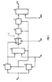
- FIG. 1 one is designated overall by 1 Device for detecting a sequence of abnormal ones Events under a variety of normal Events are shown in an electrical signal IS.
- the input signal IS arrives to a detector circuit (2) that the signal IS regarding a signal parameter (e.g. amplitude and / or slope) with a defined threshold compares.
- a signal parameter e.g. amplitude and / or slope
- the detector circuit (2) can also be designed in this way be that there is a fixed threshold is. Whenever an event occurs, the the defined with regard to the signal parameter Exceeds the threshold value, the detector circuit gives (2) a detection signal DS.
- the signal IS also comes to a Peak value meter (3) based on the same signal parameter how the detector circuit (2) responds.
- the detection signal DS By the detection signal DS, the one Control input of the peak value meter (3) fed is activated in such a way that it when an event occurs (detection signal DS) the maximum value of said signal parameter measures. If the switch (4) the in FIG 1 occupies the position shown, arrives by means of of the peak value meter (3) for each event occurred measured maximum value a memory (5) which is designed such that he the measured for the most recent event Maximum value and that for a defined number from successive immediately before this measured maximum events stores. Doing so each time you save the maximum value of the most recent event the maximum value of the "oldest" event deleted.
- the operations described are by the when an event of the detector circuit (2) each emitted detection signal DS controlled, the memory (5) is fed.
- the changeover switch (4) it is concerned preferably an electronic switch, by applying a changeover signal SW in its other switch position is the Memory (5) with the output of a subtracting circuit (6) connected by the detection signal DS controls the difference for each event between the associated maximum value and the Threshold value of the signal parameter forms.
- the subtracting circuit (6) the output signal of the peak value meter (3) the signal TV corresponding to the threshold value is supplied.
- One of the calculated statistical parameters the corresponding signal is sent to a comparator (8) fed this with a setpoint of statistical Characteristic signal DVA compares that fed to its other input is.
- the setpoint or the corresponding one Signal DVA is selected such that when the electrical signal IS essentially exclusively contains normal events, no output signal AS of the comparator (8) is present. However, if the signal IS is a sequence of abnormal Events or only abnormal events contains, this causes a deviation of the statistical characteristic of the target value, which the Comparator (8) based on the corresponding signals detects and by emitting an output signal AS indicates.
- the device described (1) is so able to follow sequences of abnormal events under a variety of normal events to be detected in an electrical signal IS.
- the comparator (8) be constructed so that it generates an output signal AS if that of the determined corresponding statistical parameter Signal exceeds a corresponding setpoint, falls below or a window-like setpoint range leaves.
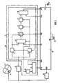
- FIG. 2 shows a device for automatic defibrillation one with a malfunction Heart (9) shown.
- Such devices that are similar like pacemakers in the body of one Can be implanted if miniaturized accordingly and in a suitable Housings are used to one called cardiac fibrillation or fibrillation State of a heart to end by the heart with electric shocks, so-called defibrillation pulses, apply. So that Device can work automatically, it must first be able to prevent the occurrence of fibrillation safe to detect. This is what the device does 2 a designated overall with (10) Fibrillation detector circuit, which the depolarization signal of the heart (9) is supplied.
- the depolarization signal is inserted into a ventricle of the heart (9) implanted electrode (11) removed and goes through a signal conditioning circuit (12) in which it is reinforced and if necessary is filtered before going to the fibrillation detector circuit (10) arrives.
- the fibrillation detector circuit (10) contains a device (1) acc. FIG 1, which is used here in the Depolarization signal of the heart (9) a consequence abnormal, suggestive of fibrillation To detect events. Relevant details will be explained later. However, it is on already pointed out here that the Memory 5 has a capacity sufficient around the maximum values or corresponding to them Data for the least 20, or typically 50 last save events that occurred and that the arithmetic circuit (7) as a parameter.
- the standard deviation determined using the comparator 8 with a corresponding setpoint or this corresponding signal DVA is compared.
- a measuring circuit (13) which by the Device (1) originating detection signals DS are supplied and the the time intervals between successive detector signals DS, i.e. one size corresponding to the heart rate measures.
- the output signal of the measuring circuit (13) arrives at a comparator (14) and is included here a signal DVS corresponding to a setpoint compared to which a certain heart rate may be exceeded if exceeded there is fibrillation.
- the comparator (14) delivers an output signal FS, just like the output signal AS of the comparator (8) one with the fibrillation detector circuit (10) related control logic (15) is supplied.
- the comparator (8) provides an output signal AS, which means that a sequence of abnormal, events suggestive of fibrillation in the depolarization signal of the heart (9) is detected the comparator (14) a signal FS that says the heart rate is in an area for a Fibrillation is typical, actuates the control logic (15) by means of a signal DEF over a corresponding designated output a generator device (16) such that this one or more Delivers defibrillation pulses to the heart (9) over the same electrode (11), which is also used for detection of the depolarization signal is used become. It goes without saying that to act upon of the heart (9) with defibrillation pulses too there may be a separate electrode.
- the fibrillation detector circuit is named (10) the signals TV, DVA, DVS and SW, the meaning of which has already been explained was supplied by the control logic (15).
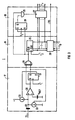
- FIG 3 which as part of the device (1) in the fibrillation detector circuit (10) of the device acc. FIG 2 Is used, performs the functions of the detector circuit (2) and the peak value meter (3) out.
- the circuit is gem. 3 as a digital circuit executed what in terms of interaction with the control logic (15) is an advantage is.
- a circuit corresponding to the circuit shown in FIG. 3 However, switching can also be done without realize another as an analog circuit, if this is desirable.
- the circuit acc. FIG 3 comprises a delta modulator (17), a counter unit (18) and a register unit (19).
- the delta modulator (17) has a comparator (20), a D flip-flop (21), current sources (22) and an integration capacitor (23).
- the inverting input of the comparator (20) is connected to a reference voltage V REF .
- the D flip-flop (21) is clocked at a frequency f 1 of 16 kHz, for example.
- the counter unit (18) has an EXCLUSIVE-OR gate (24), a counter (25) clocked at a frequency f 2 of, for example, 8 kHz and a comparator (26).
- the comparator (26) compares the output value T of the counter (25) with a target value TV, which corresponds to a specific time period t D.
- the register unit (19) contains a register (27) which is clocked via an RS flip-flop (28) and an AND gate (29), the RS flip-flop (28) in turn having a frequency f 1 is clocked.
- the register (27) serves to store the maximum output value of the counter (25), which the counter in each case reaches after the generation of a detection signal DS.
- the output of the comparator (20) remains in its state as long as the amplitude of the depolarization signal IS exceeds (+ I / C) t or ( -I / C) t exceeds or falls below, where t is the time that has passed since. below the slope + I / C or -I / C has elapsed.
- the D flip-flop (21) does not change its state either, so that the counter (25) is not reset by the EXCLUSIVE-OR gate (24).
- the output value T of the counter (25) which is a measure of the time t, begins to increase. If the output value T of the counter (25) reaches a value T D which corresponds to a minimum time period t D , the comparator (26) gives the output value of the counter (25) with the value T D which corresponds to the signal TB according to FIG and Fig. 2 corresponds, compares, to a detection signal DS indicating that an event has been detected. The counter (25) then continues to count until it is reset to zero by the EXCLUSIVE-OR gate (24).
- the AND gate (18) namely gives a clock pulse to the register (27) when, after the detection of an event, the RS flip-flop (28), the output of which is connected to one input of the AND gate (29) , and then a pulse from the EXCLUSIVE-OR gate (24) arrives at the other input of the AND gate (29).
- the circuit according to. 3 shows the signal parameter, with respect to which the depolarization signal IS is compared to a threshold value and with respect to which the maximum value is measured, is the length of time for which the amplitude of the depolarization signal IS exceeds or falls below a value that results from the product of a defined one Slope + I / C or -I / C and that time period t that has elapsed since the slope at which the slope of the depolarization signal IS reaches the defined slope + I / C or -I / C.
- a waveform In order for a waveform to be detected as an event in the depolarization signal IS, it must therefore exceed or fall below a certain slope + I / C or -I / C, reach a certain minimum time period t D and a certain minimum amplitude (+ I / C) t or (-I / C) t.
- FIG 4 shows the depolarization signal of a heart working in the sinus rhythm, that is to say in the normal rhythm, as is shown in the device at the output of the signal processing circuit (12).
- FIG 2 is present.
- the section of the depolarization signal shown contains 3 events, which are designated by I to III.
- the device 1 continuously checks, following the clock of the frequency f 1 , whether the depolarization signal has a slope which exceeds or exceeds the value + I / C. falls below the value -I / C. As long as this is not the case, the counter (25) is continuously reset.
- event I has a slope for the first time at time t 0 , which falls below the value -I / C.
- the counter (25) measures the time period t T until the point in time at which the amplitude of the depolarization signal exceeds the value (-I / C) t.
- the course of the straight line (-I / C) t is entered in FIG. 4, this straight line affecting the depolarization signal at time t 0 and intersecting after the total time period t T has elapsed. Since in the event of event I the total time period t T exceeds a minimum time period t D , for example 6 ms, the device (1) generates a detection signal DS after the minimum time t D has elapsed. Data corresponding to the total time period t T are transferred to the memory (5).
- the corresponding depolarization signal is shown in FIG. 5.
- the total time periods t T determined for the individual events fluctuate considerably.
- FIG. 5 which shows the depolarization signal of a heart operating according to the sinus rhythm
- FIG. 5 shows the rising edges of the events so steep that detection is possible. This means that two detection signals DS are sometimes generated for events IV to XI, since the minimum time period t D is exceeded both in the case of the falling and the rising edge of an event.
- control logic (15) As shown in FIG 2 using the connection TM the control logic (15) and connected to it Transmitting / receiving coil (30) can be seen the control logic (15) is designed such that the Device acc. 2 with a not shown Communicate external device bidirectionally telemetrically can. Accordingly, there is the possibility the data stored in the control logic (15) check for signals DVA, DVS, TV and change if necessary. The same possibility also exists regarding the adjustability of the Power sources (22) and another, additional possible detection criterion, namely the polarity change I / C, + I / C or -I / C for the slope.
- the frequencies f 1 , f 2 are derived in a generally known and therefore not shown manner from the oscillation frequency of a crystal (31) connected to the control logic (15) via the connection C1.
Landscapes
- Health & Medical Sciences (AREA)
- Cardiology (AREA)
- Life Sciences & Earth Sciences (AREA)
- Public Health (AREA)
- Heart & Thoracic Surgery (AREA)
- Engineering & Computer Science (AREA)
- Biomedical Technology (AREA)
- Veterinary Medicine (AREA)
- Animal Behavior & Ethology (AREA)
- General Health & Medical Sciences (AREA)
- Nuclear Medicine, Radiotherapy & Molecular Imaging (AREA)
- Radiology & Medical Imaging (AREA)
- Physics & Mathematics (AREA)
- Biophysics (AREA)
- Pathology (AREA)
- Medical Informatics (AREA)
- Molecular Biology (AREA)
- Surgery (AREA)
- Electrotherapy Devices (AREA)
- Measurement And Recording Of Electrical Phenomena And Electrical Characteristics Of The Living Body (AREA)
- Measuring Pulse, Heart Rate, Blood Pressure Or Blood Flow (AREA)
Description
Einrichtung zum Delektieren einer Folge von anormalen Ereignissen in einem elecktrodenphysiologischen Signal, insbesondere dem Depolarisationssignal eines Herzens.Device for detecting a Sequence of abnormal events in one electrode physiological signal, in particular the depolarization signal of a heart.
Die Erfindung betrifft eine Einrichtung zum Detektieren einer Folge von anormalen Ereignissen unter einer Vielzahl von normalen Ereignissen in einem elektrophysiologischen Signal. Die Ausführungsformen der Erfindung betreffen ausserdem eine Einrichtung zum Detektieren einer Folge von auf eine Fibrillation hindeutenden Ereignissen unter einer Vielzahl von normalen Ereignissen in dem Depolarisationssignal eines eine Funktionsstörung aufweisenden Herzens, eine Einrichtung zum Detektieren der Fibrillation eines eine Funktionsstörung aufweisenden Herzens sowie eine Einrichtung zur selbsttätigen Defibrillation eines eine Funktionsstörung aufweisenden Herzens.The invention relates to a Means for detecting a sequence of abnormal ones Events under a variety of normal Events in an electrophysiological signal. The embodiments of the invention relate to also a device for detection a sequence of indications of fibrillation Events under a variety of normal Events in the depolarization signal a malfunctioning heart, a Device for detecting the fibrillation of a a malfunctioning heart and a device for automatic defibrillation a malfunctioning heart.
Das Detektieren einer Folge von anormalen Ereignissen unter einer Vielzahl von normalen Ereignissen in einem elektrophysiologischen Signal spielt z.B. bei der Detektion von Arrhythmien anhand des Depolarisationssignals eines eine Funktionsstörung aufweisenden Herzens eine Rolle. Das Depolarisationssignal eines eine Funktionsstörung aufweisenden Herzens enthält neben auf normale Herztätigkeit hindeutenden Wellenformen beim Auftreten einer Arrhythmie, z.B. Herzflimmern (Fibrillation), Wellenformen, die von den im Falle von normaler Herztätigkeit vorliegenden Wellenformen abweichen. Fasst man die jeweils einem normalen oder anormalen Herzschlag entsprechenden Wellenformen als normales bzw. anormales Ereignis in dem Depolarisationssignal des Herzens auf, stellt eine Arrhythmie eine Folge von anormalen Ereignissen unter einer Vielzahl von normalen Ereignissen dar.Detecting a sequence of abnormal ones Events under a variety of normal events in an electrophysiological signal plays e.g. in the detection of arrhythmias based on the depolarization signal of a malfunction having a heart. The Depolarization signal of a malfunction showing heart contains in addition to normal Waveforms indicative of cardiac activity Arrhythmia, e.g. Cardiac fibrillation (fibrillation), Waveforms from those in the case of waveforms present in normal cardiac activity differ. If you take a normal one or waveforms corresponding to abnormal heartbeat as a normal or abnormal event in the depolarization signal of the heart an arrhythmia is a sequence of abnormal events under a variety of normal events represents.
Da im Zusammenhang mit Arrhythmien lebensbedrohliche Situationen für den Patienten auftreten können, ist es wünschenswert, eine Folge von auf eine Arrhythmie hindeutenden Ereignissen unter einer Vielzahl von normalen Ereignissen in dem Depolarisationssignal eines Herzens rasch und zuverlässig detektieren zu können, um etwa erforderliche therapeutische Massnahmen rechtzeitig einleiten zu können. Insbesondere im Zusammenhang mit selbsttätigen Defibrillatoren ist es unerlässlich, eine Folge von auf eine Fibrillation des Herzens hindeutenden Ereignissen unter einer Vielzahl von normalen Ereignissen sicher und zuverlässig detektieren zu können. Nur so ist sichergestellt, dass einerseits das Herz die zur Beendigung der Fibrillation erforderlichen Defibrillationsimpulse auch tatsächlich erhält und andererseits unnötige Defibrillationsimpulse, die katastrophale Folgen nach sich ziehen können, vermieden sind.Because life-threatening in connection with arrhythmias Situations arise for the patient can, it is desirable to have a sequence of on an arrhythmia suggestive event under a Variety of normal events in the depolarization signal of a heart quickly and reliably to be able to detect, if necessary Initiate therapeutic measures in good time to be able to. Especially related with automatic defibrillators, it is essential a consequence of fibrillation of the heart indicative events among a variety of Detect normal events safely and reliably to be able to. This is the only way to ensure that on the one hand, the heart to stop fibrillation necessary defibrillation pulses actually receives and on the other hand unnecessary defibrillation pulses, the catastrophic aftermath can pull are avoided.
In der US-Patentschrift 3,861,387 ist ein Gerät zur Detektion von Herzrhytmusstörungen beschrieben. Dabei wird ein der elektrischen Aktivität des Herzens entsprechendes Signal gewonnen und von diesem Signal die erste Ableitung nach der Zeit gebildet. Für jede normale oder anormale Tätigkeit des Herzens, also für jedes normale oder anormale Ereignis in dem differenzierten Signal, wird die Spitzenamplitude ermittelt und für eine bestimmte Anzahl der zuletzt gemessenen Spitzenamplituden laufend der Mittelwert gebildet. Ausgehend von diesem fortlaufend ermittelten Mittelwert wird ein Schwellwert definiert und für jedes Ereignis in dem differenzierten Signal die Zeitdauer ermittelt, für die sich die Amplitude während der Dauer des Ereignisses oberhalb des Schwellwertes bewegt. Auch bezüglich einer bestimmten Anzahl von jeweils zuletzt gemessenen Zeitdauern wird fortlaufend der Mittelwert gebildet. Für jedes in dem differenzierten Signal aufgetretene Ereignis wird sowohl die Spitzenamplitude als auch die Zeitdauer, für die sich die Amplitude oberhalb des Schwellwertes bewegte, mit dem Mittelwert verglichen. Sobald ein Ereignis bezüglich wenigstens eines Mittelwertes eine Abweichung aufweist, die einen bestimmten Grenzwert überschreitet, wird ein Signal erzeugt, das auf das Vorliegen eines anormalen Ereignisses hindeutet. Der Entscheidung, ob ein anormales oder ein normales Ereignis vorliegt, liegt also kein objektives Kriterium zugrunde. Sie erfolgt vielmehr anhand von Kriterien, nämlich Mittelwerten, die aus dem zu untersuchenden Signal abgeleitet sind. Dies mag noch zu brauchbaren Ergebnissen führen, solange einzelne anormale Ereignisse zu detektieren sind, insbesondere da als anormal detektierte Ereignisse bei der Bildung der Mittelwerte ausser Betracht bleiben. Die Detektion von Folgen von anormalen Ereignissen, die im Falle der US-A-3,861,387 in der Weise erfolgen soll, dass die Abgabe von auf anormale Ereignisse hindeutenden Signalen solange unterbunden wird, bis eine bestimmte Anzahl von anormalen Ereignissen in einem definierten Zeitintervall detektiert wurde, ist jedoch nicht mit ausreichender Zuverlässigkeit möglich. Verändert sich nämlich ein zunächst im wesentlichen nur objektiv normale Ereignisse enthaltendes Signal allmählich, also ohne dass in nennenswertem Umfang Detektionen anormaler Ereignisse auftreten, dahingehend, dass Folgen von Ereignissen oder sämtliche Ereignisse in dem Signal objektiv als anormal einzustufen sind, werden diese Ereignisse dennoch nicht detektiert, da mit der allmählichen Veränderung des Signals eine allmähliche Veränderung der Mittelwerte stattgefunden hat und nun objektiv anormale Ereignisse fälschlicherweise als normale Ereignisse angesehen werden. There is one device in U.S. Patent 3,861,387 described for the detection of cardiac arrhythmias. This is one of the electrical activity of the Appropriate signal obtained from the heart and from this signal the first derivative after time educated. For any normal or abnormal job of the heart, so for every normal or abnormal Event in the differentiated signal, the Peak amplitude determined and for a specific Number of the most recently measured peak amplitudes the mean is continuously formed. Starting from this continuously determined mean is a Threshold defined and for each event in the differentiated signal determines the length of time for which the amplitude during the duration of the event moved above the threshold. Also for a certain number of last measured time periods is continuously the Average formed. For each in the differentiated Signal occurring event becomes both the peak amplitude as well as the amount of time for which the amplitude moved above the threshold, compared to the mean. As soon as an event with respect to at least one mean Deviation that has a certain limit exceeds a signal that is generated indicates the presence of an abnormal event. Deciding whether an abnormal or a normal event, there is no objective Criterion. Rather, it is based on of criteria, namely mean values derived from the investigating signal are derived. This likes still lead to usable results as long individual abnormal events are to be detected, especially since events detected as abnormal disregarded when averaging stay. The detection of consequences of abnormal Events that occurred in the case of US-A-3,861,387 Way that the delivery of abnormal Signals indicating events as long as is prevented until a certain number of abnormal events in a defined time interval was detected, but is not sufficient Reliability possible. Changes namely an initially only objective signal containing normal events gradually, So without significant detections abnormal events occur in that that episodes of events or all Objectively classify events in the signal as abnormal are these events nonetheless not detected because of the gradual change a gradual change in the signal Averages have occurred and are now objectively abnormal Events incorrectly as normal events be considered.
In der US-Patentschrift 4 523 595 ist ein Gerät zur Detektion eines Fibrillationszustandes des Herzens beschrieben. Bei diesem Gerät werden Werte, bezüglich typischer Parameter des Herzsignals, mit eingespeicherten Werten dieser Parameter für verschiedene Herzzustände verglichen. Da bei einem Fibrillationszustand das Herzsignal völlig unorganisiert ist, kann dieser Zustand festgestellt werden, wenn keine von den dabei vorliegenden Parameterwerten eine Ähnlichkeit mit den eingespeicherten Werten zeigen. Dieses Gerät benutzt nicht nur die Spitzenamplitude des abgeleiteten Herzsignals, sondern zusätzlich auch noch z.B die Spitzenamplitude des Herzsignals selbst, wobei die Spitzenamplitude eines Ereignisses mit einem Mittelwert der des zu untersuchenden (Herz)signals, verglichen wird. Auch bei diesem Gerät liegt also der Entscheidung, ob ein anormaler Zustand vorliegt, kein objektives Kriterium zugrunde.In U.S. Patent 4,523,595 there is an apparatus for the detection of a fibrillation state of the heart described. With this device, values, regarding typical parameters of the heart signal, with stored values of these parameters for compared different heart conditions. There with one Fibrillation state the heart signal completely disorganized this state can be determined if none of the available parameter values a similarity to the stored ones Show values. This device does not use only the peak amplitude of the derived heart signal, but also additionally e.g. the peak amplitude of the heart signal itself, the Peak amplitude of an event with an average that of the (heart) signal to be examined, is compared. So this device also lies deciding whether there is an abnormal condition no objective criterion.
Der Erfindung liegt die Aufgabe zugrunde, eine Einrichtung zum Detektieren einer Folge von anormalen Ereignissen in einem elektrophysiologischen Signal, insbesondere dem Depolarisationssignal eines Herzens, so auszubilden, dass die Detektion einer Folge von anormalen Ereignissen in dem Signal unter allen Umständen, insbesondere auch bei allmählichen Änderungen der Erscheinungsform der Ereignisse, mit hoher Zuverlässigkeit gewährleistet ist.The invention is based on the object a device for detection a sequence of abnormal events in one electrophysiological signal, especially the Depolarization signal of a heart to train so that the detection of a sequence of abnormal Events in the signal under all circumstances, especially with gradual changes the manifestation of events, with high Reliability is guaranteed.
Im Falle der erfindungsgemässen Einrichtung wird also bezüglich der Maximalwerte eines für die jeweils zu detektierenden Ereignisse typischen Signalparameters, es kann sich hierbei z.B. um die Amplitude, die Steilheit (slope) des Signals, dessen Frequenz usw. handeln, eine deren statistischer Verteilung entsprechende Kenngrösse ermittelt. Diese wird mit einem Sollwert der Kenngrösse verglichen, um entscheiden zu können, ob die bei der Bildung der Kenngrösse berücksichtigten Ereignisse eine Folge von anormalen Ereignissen enthalten bzw. selbst Bestandteile einer Folge von anormalen Ereignissen sind. Die Detektion einer Folge von anormalen Ereignissen erfolgt also anhand eines objektiven Kriteriums, da der Sollwert der Kenngrösse in keiner Weise von dem Verlauf des Signals abhängt. Wesentlich ist ausserdem, dass das Signal hinsichtlich desjenigen Signalparameters, dessen Maximalwerte für jedes Ereignis gemessen werden, mit einem definierten Schwellwert verglichen wird, den das Signal sowohl beim Auftreten eines normalen als auch eines anormalen Ereignisses überschreitet. Durch geeignete Wahl des Schwellwertes kann also vermieden werden, dass Störungen oder dergleichen fälschlicherweise als Ereignis angesehen und bei der Ermittlung der der statistischen Verteilung der gemessenen Maximalwerte entsprechenden Kenngrösse berücksichtigt werden. Die Einrichtung gestattet es also, eine Folge von anormalen Ereignissen unter einer Vielzahl von normalen Ereignissen in einem elektrischen Signal mit hoher Zuverlässigkeit zu detektieren. Dabei steigt die Zuverlässigkeit der Detektion mit der Anzahl von Ereignissen, die zur Ermittlung der statistischen Verteilung der gemessenen Maximalwerte entsprechenden Kenngrösse herangezogen werden. Es versteht sich, dass zugleich diejenige Zeit steigt, die von dem Auftreten einer Folge von anormalen Ereignissen bis zu demjenigen Zeitpunkt vergeht, zu dem der Vergleich der ermittelten Kenngrösse mit dem Sollwert der Kenngrösse auf das Vorhandensein einer Folge von anormalen Ereignissen hindeutet. Es muss also ein Kompromiss zwischen der zur Detektion erforderlichen bzw. zulässigen Zeit und der Anzahl der zur Ermittlung der Kenngrösse heranzuziehenden Anzahl von Ereignissen geschlossen werden. Aus den vorstehenden Ausführungen wird klar, dass die erfindungsgemässe Einrichtung zum Detektieren einzelner anormaler Ereignisse unter einer Vielzahl von normalen Ereignissen weniger geeignet ist.In the case of the device according to the invention is therefore one for the maximum values signal parameters typical of each event to be detected, it can e.g. to the Amplitude, the slope of the signal, its Frequency, etc. act, one of them statistical Distribution determined the relevant parameter. This is with a setpoint of the parameter compared to be able to decide whether the at events taking into account the formation of the parameter a sequence of abnormal events contain or even components of a sequence of abnormal events. The detection of one The sequence of abnormal events is based on an objective criterion because the setpoint the characteristic in no way from the course of the signal depends. It is also essential that the signal with respect to that signal parameter, its maximum values for each event be measured with a defined threshold is compared, the signal at both Occurrence of normal as well as abnormal Event. By suitable choice the threshold value can thus be avoided that glitches or the like wrongly regarded as an event and in determining the the statistical distribution of the measured maximum values corresponding parameter is taken into account become. The facility allowed so it is a sequence of abnormal events under a variety of normal events in an electrical signal with high reliability to detect. The reliability increases of detection with the number of events that to determine the statistical distribution of the measured Maximum values corresponding characteristic be used. It goes without saying that at the same time that time increases from that Occurrence of a sequence of abnormal events by the time the Comparison of the determined parameter with the target value the parameter on the presence of a Sequence of abnormal events suggests. It So there has to be a compromise between detection required or permitted time and the Number of those to be used to determine the parameter Number of events closed become. The above statements become clear that the inventive device for Detect individual abnormal events below a lot of normal events less suitable is.
Als der statistischen Verteilung der gemessenen Maximalwerte entsprechende Kenngrösse kommt z.B. der arhithmetische Mittelwert in Frage. Gemäss einer besonders vorteilhaften Ausführungsform der Erfindung wird als der statistischen Verteilung der gemessenen Maximalwerte entsprechende Kenngrösse die Standardabweichung ermittelt. Die Standardabweichung gestattet selbst dann, wenn die gemessenen Maximalwerte der Ereignisse innerhalb gewisser Grenzen streuen, eine exakte Entscheidung darüber, ob eine Folge anormaler Ereignisse vorliegt oder nicht.As the statistical distribution of the measured Maximum values corresponding characteristic comes e.g. the arhithmetic mean in question. According to a particularly advantageous embodiment the invention is called the statistical Distribution of the measured maximum values accordingly The standard deviation is determined. The standard deviation allows itself then when the measured maximum values of the events scatter within certain limits, one exact decision as to whether an episode is abnormal Events or not.
Bezüglich der Definition der üblicherweise mit
dem Formelzeichen S bezeichneten Standardabweichung
wird auf das Buch von Dr.-Ing. W. Walcher,
Praktikum der Physik, 3, Auflage, Verlag B.G.
Teubner, Stuttgart, 1974, Seiten 24 ff. verwiesen.
Analoge oder digitale Schaltungen zur Ermittlung
der Standardabweichung sind übrigens aus dem
Stand der Technik bekannt.Regarding the definition of usually with
the standard deviation denoted by the symbol S.
is based on the book by Dr.-Ing. W. Walcher,
Internship in Physics, 3rd edition, published by B.G.
Teubner, Stuttgart, 1974,
Nach einer Ausführungsform der Erfindung wird für jedes Ereignis die Differenz zwischen dem Maximalwert und dem Schwellwert des Signalparameters berechnet und jeweils der Ermittlung der statistischen Verteilung der gemessenen Maximalwerte entsprechenden Kenngrösse zugrundegelegt. Die Standardabweichung wird also anhand eines sogenannten Detektionsmariginals, das, falls dies wünschenswert ist, auch als Bruchteil oder Prozentsatz des Schwellwertes ausgedrückt werden kann, ermittelt. Dies ist besonders anschaulich, da die Relationen der Maximalwerte zu dem Schwellwert sofort erkennbar sind.According to one embodiment of the invention the difference between the Maximum value and the threshold value of the signal parameter calculated and each time determining the statistical distribution of the measured maximum values based on the relevant parameter. The standard deviation is therefore based on a so-called detection masters, which, if this is desirable, also as a fraction or percentage of the threshold value can be expressed can, determined. This is particularly clear because the relations of the maximum values to the threshold value are immediately recognizable.
Die Aufgabe
wird durch die Einrichtung gemäss Patentanspruch
1 gelöst.The task
is by the device according to
Die Vorteile dieser Einrichtung ergeben sich aus der vorangegangenen Beschreibung. Die Einrichtung besitzt ausserdem einen einfachen Aufbau, da Mittel zur Messung des Maximalwertes und Mittel zum Ermitteln einer der statistischen Verteilung der gemessenen Maximalwerte entsprechenden Kenngrösse nur bezüglich eines einzigen Signalparameters vorhanden sein müssen, wobei gemäss einer bevorzugten Ausführungsform der Erfindung die Mittel zum Ermitteln einer der statistischen Verteilung der gemessenen Maximalwerte entsprechenden Kenngrösse die Standardabweichungen ermitteln. Für den Fall, dass aus Gründen der Anschaulichkeit bezuglich der einzelnen Ereignisse deren Maximalwerte in Relation zu dem Schwellwert als Detektionsmariginal angegeben werden soll, sind gemäss einer Ausführungsform der Erfindung Mittel zur Bestimmung der Differenz zwischen dem jeweils für ein Ereignis gemessenen Maximalwert und dem Schwellwert des Signalparameters vorgesehen, wobei den Mitteln zum Ermitteln einer statistischen Verteilung der gemessenen Maximalwerte entsprechenden Kenngrösse bezüglich der einzelnen Ereignisse jeweils die Differenzen zugeführt sind.The advantages of this facility result from the previous description. The facility owns also a simple structure, because means for measuring the maximum value and mean for Determine one of the statistical distribution of the measured Maximum values corresponding characteristic only with regard to a single signal parameter must be present, whereby according to one preferred embodiment of the invention Means for determining one of the statistical distribution corresponding to the measured maximum values Determine the standard deviations. In the event that for reasons of clarity with regard to the individual events Maximum values in relation to the threshold as Detection original to be specified are according to an embodiment of the invention means to determine the difference between the maximum value measured for each event and the threshold value of the signal parameter is provided, the means for determining a statistical Distribution of the measured maximum values corresponding parameter with regard to the individual Events each fed the differences are.
Eine Einrichtung zum Detektieren einer Folge von auf eine Fibrillation hindeutenden Ereignissen unter einer Vielzahl von normalen Ereignissen in dem Depolarisationssignal eines einer Funktionsstörung aufweisenden Herzens ist im Patentanspruch 4 angegeben.Means for detecting a sequence of events indicative of fibrillation under a variety of normal events in the depolarization signal of a malfunction having a heart is in the claim 4 specified.
Als Signalparameter wird also diejenige Zeitdauer herangezogen, für die die Amplitude des Signals jeweils beginnend von einem Zeitpunkt, zu dem die Steilheit des Depolarisationssignals eine definierte Steilheit erreicht, mindestens dem Produkt aus definierter Steilheit und verstrichener Zeit entspricht. Den Schwellwert bildet somit eine Mindestzeitdauer, die das Depolarisationssignal sowohl beim Auftreten eines normalen als auch eines auf eine Fibrillation hindeutenden Ereignisses überschreitet. Als Maximalwert wird die Gesamtzeitdauer gemessen, für die die Amplitude des Depolarisationssignals während des jeweiligen Ereignisses mindestens dem Produkt aus definierter Steilheit und verstrichener Zeit entspricht Als statistische Kenngrösse wird schliesslich die Standardabweichung der Gesamtzeitdauern bzw. von den Gesamtzeitdauern entsprechenden Grössen (Detektionsmarginal) ermittelt.That time period is therefore the signal parameter used for which the amplitude of the Signals starting from a point in time which the steepness of the depolarization signal defined steepness reached, at least the product from defined steepness and elapsed time equivalent. The threshold value thus forms a minimum period of time, which both the depolarization signal when a normal as well as one occurs exceeds an indicative event of fibrillation. The total time is the maximum value measured for which the amplitude of the depolarization signal during the respective event at least the product of defined steepness and elapsed time corresponds to being statistical The parameter ultimately becomes the standard deviation of the total time periods or of the total time periods corresponding sizes (detection margin) determined.
Es wurde festgestellt, dass das Depolarisationssignal des Herzens im Falle von normalen Herzschlägen (Sinus-Rhythmus) für jedes Ereignis etwa die gleiche Gesamtzeitdauer aufweist, für die die Amplitude des Depolarisationssignals während des jeweiligen Ereignisses mindestens dem Produkt aus definierter Steilheit und verstrichener Zeit entspricht. Entsprechend gering ist die der Standardabweichung der für das jeweils zuletzt aufgetretene und eine definierte Anzahl von fortlaufend unmittelbar vor diesem aufgetretenen Ereignissen gemessene Gesamtzeitdauern entsprechende statistische Kenngrösse. Folgt das Herz nicht mehr dem Sinus-Rhythmus, was z.B. im Falle von Fibrillation der Fall ist, schwanken die für die einzelnen Ereignisse gemessenen Gesamtzeitdauern ganz erheblich, was seinen Niederschlag in einer Vergrösserung der Standardabweichung der Gesamtzeitdauern findet. Mittels der erfindungsgemässen Einrichtung ist also eine zuverlässige Detektion einer Folge von anormalen Ereignissen, denen ein anderer als der Sinus-Rhythmus zugrunde liegt, möglich. Dies bedeutet, dass Folgen von anormalen Ereignissen detektierbar sind, die auf eine Fibrillation des Herzens hindeuten.It was found that the depolarization signal of the heart in the case of normal Heartbeats (sinus rhythm) for every event has approximately the same total amount of time for which the amplitude of the depolarization signal during of the respective event at least the product from defined steepness and elapsed time equivalent. The standard deviation is correspondingly low the one for the last one that occurred and a defined number of consecutive immediately before this occurred event measured total time corresponding statistical Characteristic variable. The heart no longer follows the sinus rhythm, which e.g. in the case of fibrillation the case is that fluctuate for the individual Total time measured by events, what its precipitation in an enlargement the standard deviation of the total time periods place. By means of the device according to the invention is therefore a reliable detection of one Sequence of abnormal events that another than the sinus rhythm is possible. This means that episodes of abnormal Events are detectable due to fibrillation of the heart.
Eine Einrichtung zum Detektieren der Fibrillation eines eine Funktionsstörung aufweisenden Herzens ist im Patentanspruch 5 angegeben.A device for detecting fibrillation one with a malfunction Heart is specified in claim 5.
Es wird hier also nicht nur die Standardabweichung der im Zusammenhang mit einer definierten Anzahl von zuletzt aufgetretenen Ereignissen gemessenen Gesamtzeitdauern bzw. eine dieser entsprechende statistische Kenngrösse, sondern zusätzlich die Herzschlagfrequenz, die beim Auftreten von Fibrillationen oberhalb einer bestimmten Grenze liegt, berücksichtigt. Somit ist eine zuverlässige Detektion der Fibrillation des Herzens gewährleistet.So it's not just the standard deviation here the context of a defined Number of recent events measured Total time periods or one corresponding to these statistical parameter, but additionally the heartbeat rate when it occurs of fibrillation above a certain limit lies, taken into account. It is therefore a reliable one Detection of fibrillation of the heart is guaranteed.
Eine Einrichtung zur selbsttätigen Defibrillation
eines eine Funktionsstörung aufweisenden Herzens
weist gemäss Patentanspruch 6 zusätzlich Mittel
zur Beaufschlagung des Herzens mit Defibrillationsimpulsen
auf, die mit den Mitteln zum Erzeugen
eines Signales verbunden sind und bei Vorliegen
eines Signales das Herz mit wenigstens einem
Defibrillationsimpuls beaufschlagen. Da die Mittel
zum Erzeugen eines Signals wie erwähnt ein Signal
nur abgeben, wenn zwei Bedingungen erfüllt
sind, ist die Gefahr, dass das Herz mit Defibrillationsimpulsen
beaufschlagt wird, ohne dass eine
Fibrillation vorliegt, äusserst gering.A device for automatic defibrillation
a malfunctioning heart
has additional means according to
Im Folgenden wird die Erfindung anhand von 6 FIG näher erläutert. Es zeigen:
- FIG 1
- in Form eines Blockschaltbildes eine erfindungsgemässe Einrichtung zur Detektion einer Folge von anormalen Ereignissen unter einer Vielzahl von normalen Ereignissen in einem elektrischen Signal
- FIG 2
- eine Einrichtung zur selbsttätigen Defibrillation eines eine Funktionsstörung aufweisenden Herzens, welche eine Einrichtung gem. FIG 1 enthält, als Blockschaltbild.
- FIG 3
- in detaillierter Darstellung einen Teil der Schaltung der Einrichtung gem. FIG 2,
- FIG 4
- das eine Anzahl von aufeinanderfolgenden normalen Ereignissen enthaltende Depolarisationssignal eines Herzens, und
- FIG 5
- das eine Folge von anormalen, auf eine Fibrillation hindeutenden Ereignissen enthaltende Depolarisationssignal eines eine Funktionsstörung aufweisenden Herzens.
- FIG. 1
- In the form of a block diagram, a device according to the invention for detecting a sequence of abnormal events among a large number of normal events in an electrical signal
- FIG 2
- a device for the automatic defibrillation of a malfunctioning heart, which device according to. 1 contains, as a block diagram.
- FIG 3
- in a detailed representation part of the circuit of the device acc. FIG 2,
- FIG 4
- the heart depolarization signal containing a number of consecutive normal events, and
- FIG 5
- which is a sequence of abnormal depolarization signals from a heart with a dysfunction, indicative of fibrillation events.
In FIG 1 ist eine insgesamt mit 1 bezeichnete Einrichtung zur Detektion einer Folge von anormalen Ereignissen unter einer Vielzahl von normalen Ereignissen in einem elektrischen Signal IS dargestellt. Gemäss FIG 1 gelangt das Eingangssignal IS zu einer Detektorschaltung (2), die das Signal IS bezüglich eines Signalparameters (z.B. Amplitude und/oder Steilheit) mit einem definierten Schwellwert vergleicht. Im Falle der FIG 1 wird ein dem definierten Schwellwert entsprechendes Signal TV der Detektorschaltung (2) von aussen zugeführt, so dass die Höhe des Schwellwertes, den das Signal IS sowohl beim Auftreten eines normalen als auch eines anormalen Ereignisses überschreitet, durch Verändern des Signales TV programmierbar ist. Die Detektorschaltung (2) kann aber auch so ausgebildet sein, dass ein fester Schwellwert vorhanden ist. Jedesmal, wenn ein Ereignis auftritt, das hinsichtlich des Signalparameters den definierten Schwellwert überschreitet, gibt die Detektorschaltung (2) ein Detektionssignal DS ab.In FIG. 1, one is designated overall by 1 Device for detecting a sequence of abnormal ones Events under a variety of normal Events are shown in an electrical signal IS. According to FIG 1, the input signal IS arrives to a detector circuit (2) that the signal IS regarding a signal parameter (e.g. amplitude and / or slope) with a defined threshold compares. In the case of FIG 1 is a defined threshold corresponding signal TV supplied to the detector circuit (2) from the outside, so that the level of the threshold that the signal IS both when a normal as well as of an abnormal event Changing the signal TV is programmable. The detector circuit (2) can also be designed in this way be that there is a fixed threshold is. Whenever an event occurs, the the defined with regard to the signal parameter Exceeds the threshold value, the detector circuit gives (2) a detection signal DS.
Das Signal IS gelangt ausserdem zu einem Spitzenwertmesser (3), der auf den gleichen Signalparameter wie die Detektorschaltung (2) anspricht. Durch das Detektionssignal DS, das einem Steuereingang des Spitzenwertmessers (3) zugeführt ist, wird dieser derart aktiviert, dass er jedesmal beim Auftreten eines Ereignisses (Detektionssignal DS) den Maximalwert des besagten Signalparameters misst. Falls der Umschalter (4) die in FIG 1 dargestellte Stellung einnimmt, gelangt der mittels des Spitzenwertmessers (3) für das jeweils aufgetretene Ereignis gemessene Maximalwert zu einem Speicher (5), der derart ausgebildet ist, dass er den für das zuletzt aufgetretene Ereignis gemessenen Maximalwert und die für eine definierte Anzahl von aufeinanderfolgend unmittelbar vor diesem aufgetretenen Ereignissen gemessenen Maximalwerte speichert. Dabei wird jeweils beim Speichern des Maximalwertes des zuletzt aufgetretenen Ereignisses der Maximalwert des "ältesten" Ereignisses gelöscht. Die beschriebenen Vorgänge werden durch das beim Auftreten eines Ereignisses von der Detektorschaltung (2) jeweils abgegebene Detektionssignal DS gesteuert, das dem Speicher (5) zugeführt ist.The signal IS also comes to a Peak value meter (3) based on the same signal parameter how the detector circuit (2) responds. By the detection signal DS, the one Control input of the peak value meter (3) fed is activated in such a way that it when an event occurs (detection signal DS) the maximum value of said signal parameter measures. If the switch (4) the in FIG 1 occupies the position shown, arrives by means of of the peak value meter (3) for each event occurred measured maximum value a memory (5) which is designed such that he the measured for the most recent event Maximum value and that for a defined number from successive immediately before this measured maximum events stores. Doing so each time you save the maximum value of the most recent event the maximum value of the "oldest" event deleted. The operations described are by the when an event of the detector circuit (2) each emitted detection signal DS controlled, the memory (5) is fed.
Wird der Umschalter (4), es handelt sich hierbei vorzugsweise um einen elektronischen Umschalter, durch Anlegen eines Umschaltsignales SW in seine andere Schaltposition gebracht, ist der Speicher (5) mit dem Ausgang einer Subtrahierschaltung (6) verbunden, die durch das Detektionssignal DS gesteuert für jedes Ereignis die Differenz zwischen dem zugehörigen Maximalwert und dem Schwellwert des Signalparameters bildet. Zu diesem Zweck ist der Subtrahierschaltung (6) ausser dem Ausgangssignal des Spitzenwertmessers (3) das dem Schwellwert entsprechende Signal TV zugeführt.If the changeover switch (4), it is concerned preferably an electronic switch, by applying a changeover signal SW in its other switch position is the Memory (5) with the output of a subtracting circuit (6) connected by the detection signal DS controls the difference for each event between the associated maximum value and the Threshold value of the signal parameter forms. To this Purpose is the subtracting circuit (6) the output signal of the peak value meter (3) the signal TV corresponding to the threshold value is supplied.
Je nach Stellung des Umschalters (4) sind also für das zuletzt aufgetretene Ereignis und eine definierte Anzahl unmittelbar vor diesem aufgetretenen Ereignissen entweder die Maximalwerte des Signalparameters oder die Differenzen zwischen diesen Maximalwerten und dem Schwellwert gespeichert, wobei die Differenzen den Detektionsmarginalen für die jeweiligen Ereignisse entsprechen.Depending on the position of the switch (4) for the most recent event and a defined one Number immediately before this Events either the maximum values of the signal parameter or the differences between them Maximum values and the threshold value stored, where the differences are the detection margins for the respective events correspond.
Jedesmal beim Auftreten eines neuen Ereignisses werden die in dem Speicher (5) gespeicherten Maximalwerte bzw. Differenzen einschl. des entsprechenden Wertes für das zuletzt aufgetretene Ereignis einer Rechenschaltung (7) zugeführt, die eine der statistischen Verteilung der gemessenen Maximalwerte bzw. der errechneten Differenzen entsprechende Kenngrösse ermittelt, z.B. deren arhithmetischen Mittelwert. Die Rechenschaltung (7) ermittelt also in jedem Fall eine der statistischen Verteilung der gemessenen Maximalwerte entsprechende Kenngrösse, unabhängig davon, ob diese auf Grundlage der gemessenen Maximalwerte selbst oder den aus diesen und dem Schwellwert gebildeten Differenzen bzw. Detektionsmarginalen errechnet wird.Every time a new event occurs are stored in the memory (5) Maximum values or differences including the corresponding Value for the last occurred Event supplied to a computing circuit (7), the one of the statistical distribution of the measured Maximum values or the calculated differences appropriate parameter determined, e.g. their arithmetic Average. The arithmetic circuit (7) in any case determines one of the statistical ones Distribution of the measured maximum values accordingly Parameter, regardless of whether this based on the measured maximum values itself or the one from these and the threshold differences or detection margins formed is calculated.
Ein der errechneten statistischen Kenngrösse entsprechendes Signal wird einem Vergleicher (8) zugeführt, der dieses mit einem Sollwert der statistischen Kenngrösse entsprechenden Signal DVA vergleicht, das seinem anderen Eingang zugeführt ist. Der Sollwert bzw. das diesem entsprechende Signal DVA ist derart gewählt, dass dann, wenn das elektrische Signal IS im wesentlichen ausschliesslich normale Ereignisse enthält, kein Ausgangssignal AS des Vergleichers (8) vorhanden ist. Wenn jedoch das Signal IS eine Folge von anormalen Ereignissen bzw. ausschliesslich anormale Ereignisse enthält, bewirkt dies eine Abweichung der statistischen Kenngrösse von dem Sollwert, die der Vergleicher (8) anhand der entsprechenden Signale feststellt und durch Abgabe eines Ausgangssignales AS anzeigt. Die beschriebene Einrichtung (1) ist also in der Lage, Folgen von anormalen Ereignissen unter einer Vielzahl von normalen Ereignissen in einem elektrischen Signal IS zu detektieren.One of the calculated statistical parameters the corresponding signal is sent to a comparator (8) fed this with a setpoint of statistical Characteristic signal DVA compares that fed to its other input is. The setpoint or the corresponding one Signal DVA is selected such that when the electrical signal IS essentially exclusively contains normal events, no output signal AS of the comparator (8) is present. However, if the signal IS is a sequence of abnormal Events or only abnormal events contains, this causes a deviation of the statistical characteristic of the target value, which the Comparator (8) based on the corresponding signals detects and by emitting an output signal AS indicates. The device described (1) is so able to follow sequences of abnormal events under a variety of normal events to be detected in an electrical signal IS.
Den jeweiligen Bedürfnissen entsprechend kann der Vergleicher (8) so aufgebaut sein, dass er ein Ausgangssignal AS erzeugt, wenn das der ermittelten statistischen Kenngrösse entsprechende Signal einen entsprechenden Sollwert übersteigt, unterschreitet oder einen fensterartigen Sollwertbereich verlässt.According to the respective needs can the comparator (8) be constructed so that it generates an output signal AS if that of the determined corresponding statistical parameter Signal exceeds a corresponding setpoint, falls below or a window-like setpoint range leaves.
In FIG 2 ist ein Gerät zur selbsttätigen Defibrillation eines eine Funktionsstörung aufweisenden Herzens (9) dargestellt. Derartige Geräte, die ähnlich wie Herzschrittmacher auch in den Körper eines Lebewesens implantiert werden können, falls sie entsprechend miniaturisiert und in einem geeigneten Gehäuse aufgenommen sind, dienen dazu, einen als Herzflimmern bzw. Fibrillation bezeichneten Zustand eines Herzens zu beenden, indem sie das Herz mit Stromstössen, sogenannten Defibrillationsimpulsen, beaufschlagen. Damit ein derartiges Gerät selbsttätig arbeiten kann, muss es zunächst in der Lage sein, das Auftreten von Fibrillation sicher zu detektieren. Hierzu dient bei dem Gerät gemäß FIG 2 eine insgesamt mit (10) bezeichnete Fibrillations-Detektorschaltung, der das Depolarisationssignal des Herzens (9) zugeführt ist. Das Depolarisationssignal wird mittels einer in ein Ventrikel des Herzens (9) eingepflanzte Elektrode (11) abgenommen und durchläuft eine Signalaufbereitungsschaltung (12), in der es verstärkt und erforderlichenfalls gefiltert wird, bevor es zu der Fibrillations-Detektorschaltung (10) gelangt. Die Fibrillations-Detektorschaltung (10) enthält zum einen eine Einrichtung (1) gem. FIG 1, die hier dazu dient, in dem Depolarisationssignal des Herzens (9) eine Folge von anormalen, auf eine Fibrillation hindeutenden Ereignissen zu detektieren. Diesbezügliche Einzelheiten werden noch erläutert. Es sei jedoch an dieser Stelle bereits darauf hingewiesen, dass der Speicher 5 eine Kapazität aufweist, die ausreicht, um die Maximalwerte bzw. diesen entsprechenden Daten für die wenigsten 20, bzw. typisch 50 zuletzt aufgetretenen Ereignisse zu speichern, und dass die Rechenschaltung (7) als Kenngrösse bez. deren statistischer Verteilung die Standardabweichung ermittelt, die mittels des Vergleichers 8 mit einem entsprechenden Sollwert bzw. einem diesem entsprechenden Signal DVA verglichen wird. Ausserdem enthält die Fibrillations-Detektorschaltung (10) eine Mess-Schaltung (13), der die von der Einrichtung (1) stammenden Detektionssignale DS zugeführt sind und die die Zeitintervalle zwischen aufeinanderfolgenden Detektorsignale DS, also eine der Herzschlagfrequenz entsprechende Grösse misst. Das Ausgangssignal der MessSchaltung (13) gelangt zu einem Vergleicher (14) und wird hier mit einem einem Sollwert entsprechenden Signal DVS verglichen, dem eine bestimmte Herzschlagfrequenz entspricht, bei deren Überschreiten möglicherweise eine Fibrillation vorliegt. Im Falle des Überschreitens liefert der Vergleicher (14) ein Ausgangssignal FS, das ebenso wie das Ausgangssignal AS des Vergleichers (8) einer mit der Fibrillations-Detektorschaltung (10) verbundenen Steuerlogik (15) zugeführt ist.2 shows a device for automatic defibrillation one with a malfunction Heart (9) shown. Such devices that are similar like pacemakers in the body of one Can be implanted if miniaturized accordingly and in a suitable Housings are used to one called cardiac fibrillation or fibrillation State of a heart to end by the heart with electric shocks, so-called defibrillation pulses, apply. So that Device can work automatically, it must first be able to prevent the occurrence of fibrillation safe to detect. This is what the device does 2 a designated overall with (10) Fibrillation detector circuit, which the depolarization signal of the heart (9) is supplied. The depolarization signal is inserted into a ventricle of the heart (9) implanted electrode (11) removed and goes through a signal conditioning circuit (12) in which it is reinforced and if necessary is filtered before going to the fibrillation detector circuit (10) arrives. The fibrillation detector circuit (10) contains a device (1) acc. FIG 1, which is used here in the Depolarization signal of the heart (9) a consequence abnormal, suggestive of fibrillation To detect events. Relevant details will be explained later. However, it is on already pointed out here that the Memory 5 has a capacity sufficient around the maximum values or corresponding to them Data for the least 20, or typically 50 last save events that occurred and that the arithmetic circuit (7) as a parameter. their statistical distribution the standard deviation determined using the comparator 8 with a corresponding setpoint or this corresponding signal DVA is compared. Furthermore contains the fibrillation detector circuit (10) a measuring circuit (13), which by the Device (1) originating detection signals DS are supplied and the the time intervals between successive detector signals DS, i.e. one size corresponding to the heart rate measures. The output signal of the measuring circuit (13) arrives at a comparator (14) and is included here a signal DVS corresponding to a setpoint compared to which a certain heart rate may be exceeded if exceeded there is fibrillation. In the case of Exceeding the comparator (14) delivers an output signal FS, just like the output signal AS of the comparator (8) one with the fibrillation detector circuit (10) related control logic (15) is supplied.
Liefert der Vergleicher (8) ein Ausgangssignal AS, das besagt, dass eine Folge von anormalen, auf eine Fibrillation hindeutenden Ereignissen in dem Depolarisationssignal des Herzens (9) detektiert wurde, und liefert gleichzeitig der Vergleicher (14) ein Signal FS, das besagt, dass die Herzschlagfrequenz in einem Bereich liegt, der für eine Fibrillation typisch ist, betätigt die Steuerlogik (15) mittels eines Signales DEF über einen entsprechend bezeichneten Ausgang eine Generatoreinrichtung (16) derart, dass diese einen oder mehrere Defibrillationsimpulse abgibt, die dem Herzen (9) über die gleiche Elektrode (11), die auch zur Erfassung des Depolarisationssignales dient, zugeführt werden. Es versteht sich, dass zur Beaufschlagung des Herzens (9) mit Defibrillationsimpulsen auch eine gesonderte Elektrode vorhanden sein kann.The comparator (8) provides an output signal AS, which means that a sequence of abnormal, events suggestive of fibrillation in the depolarization signal of the heart (9) is detected the comparator (14) a signal FS that says the heart rate is in an area for a Fibrillation is typical, actuates the control logic (15) by means of a signal DEF over a corresponding designated output a generator device (16) such that this one or more Delivers defibrillation pulses to the heart (9) over the same electrode (11), which is also used for detection of the depolarization signal is used become. It goes without saying that to act upon of the heart (9) with defibrillation pulses too there may be a separate electrode.
Wie aus der FIG 2 anhand von Ausgängen der Steuerlogik (15) ersichtlich ist, die die entsprechenden Bezeichnungen tragen, werden der Fibrillations-Detektorschaltung (10) die Signale TV, DVA, DVS und SW, deren Bedeutung bereits erläutert wurde, von der Steuerlogik (15) zugeführt. As shown in FIG 2 based on outputs of Control logic (15) can be seen, the corresponding The fibrillation detector circuit is named (10) the signals TV, DVA, DVS and SW, the meaning of which has already been explained was supplied by the control logic (15).
Die in FIG 3 dargestellte detaillierte Schaltung, die als Teil der Einrichtung (1) in der Fibrillations-Detektorschaltung (10) des Gerätes gem. FIG 2 Verwendung findet, führt die Funktionen der Detektorschaltung (2) und des Spitzenwertmessers (3) aus. Dabei ist die Schaltung gem. FIG 3 als Digitalschaltung ausgeführt, was im Hinblick auf das Zusammenwirken mit der Steuerlogik (15) von Vorteil ist. Eine der in FIG 3 dargestellten Schaltung entsprechende Schaltung lässt sich jedoch auch ohne weiteres als Analog-Schaltung verwirklichen, falls dies wünschenswert ist. Die Schaltung gem. FIG 3 umfasst einen Delta-Modulator (17), eine Zählereinheit (18) und eine Registereinheit (19).The detailed circuit shown in FIG 3, which as part of the device (1) in the fibrillation detector circuit (10) of the device acc. FIG 2 Is used, performs the functions of the detector circuit (2) and the peak value meter (3) out. The circuit is gem. 3 as a digital circuit executed what in terms of interaction with the control logic (15) is an advantage is. A circuit corresponding to the circuit shown in FIG. 3 However, switching can also be done without realize another as an analog circuit, if this is desirable. The circuit acc. FIG 3 comprises a delta modulator (17), a counter unit (18) and a register unit (19).
Der Delta-Modulator (17) weist einen Komparator (20), ein D-Flip-Flop (21), Stromquellen (22) und einen Integrations-Kondensator (23) auf. Der invertierende Eingang des Komparators (20) ist mit einer Referenzspannung VREF verbunden. Das D-Flip-Flop (21) wird mit einer Frequenz f1 von beispielsweise 16 kHz getaktet. Die Zählereinheit (18) weist ein EXKLUSIV-ODER-Gatter (24), einen mit einer Frequenz f2 von beispielsweise 8 kHz getakteten Zähler (25) und einen Vergleicher (26) auf. Der Vergleicher (26) vergleicht den Ausgangswert T des Zählers (25) mit einem Sollwert TV, der einer bestimmten Zeitdauer tD entspricht. Für den Fall, dass der Ausgangswert des Zählers (25) den Schwellwert TV übersteigt, wird ein Detektionssignal DS erzeugt. Die Registereinheit (19) enthält ein Register (27), das über ein RS-Flip-Flop (28) und ein UND-Gatter (29) getaktet wird, wobei das RS-Flip-Flop (28) seinerseits mit einer Frequenz f1 getaktet ist. Das Register (27) dient dazu, den maximalen Ausgangswert des Zählers (25) zu speichern, den dieser jeweils im Anschluss an die Erzeugung eines Detektionssignals DS erreicht.The delta modulator (17) has a comparator (20), a D flip-flop (21), current sources (22) and an integration capacitor (23). The inverting input of the comparator (20) is connected to a reference voltage V REF . The D flip-flop (21) is clocked at a frequency f 1 of 16 kHz, for example. The counter unit (18) has an EXCLUSIVE-OR gate (24), a counter (25) clocked at a frequency f 2 of, for example, 8 kHz and a comparator (26). The comparator (26) compares the output value T of the counter (25) with a target value TV, which corresponds to a specific time period t D. In the event that the output value of the counter (25) exceeds the threshold value TV, a detection signal DS is generated. The register unit (19) contains a register (27) which is clocked via an RS flip-flop (28) and an AND gate (29), the RS flip-flop (28) in turn having a frequency f 1 is clocked. The register (27) serves to store the maximum output value of the counter (25), which the counter in each case reaches after the generation of a detection signal DS.
Solange die Steilheit des der Schaltung gem. FIG 3 zugeführten Depolarisationssignales IS weder den Wert + I/C überschreitet noch den Wert -I/C unterschreitet, wobei + I bzw. -I dem durch die Stromquellen (22) fliessenden Strom, der einstellbar sein kann, und C der Kapazität des Integrations-Kondensators (23) entspricht, schaltet das D-Flip-Flop (21) ständig um, was zur Folge hat, dass der Zähler (25) in der Zählereinheit (18) über das EXKLUSIV-ODER-Gatter (24) ständig auf Null zurückgesetzt wird. Überschreitet bzw. unterschreitet die Steilheit des Depolarisationssignales IS den Wert + I/C oder -I/C behält der Ausgang des Komparators (20) seinen Zustand bei, solange die Amplitude des Depolarisationssignals IS den Wert (+ I/C)t bzw. (-I/C)t über- bzw. unterschreitet, wobei t die Zeit ist, die seit dem über-bzw. unterschreiten der Steilheit + I/C bzw. -I/C verstrichen ist. Solange der Ausgangszustand des Komparators (20) konstant bleibt, ändert auch das D-Flip-Flop (21) seinen Zustand nicht, so dass der Zähler (25) von dem EXKLUSIV-ODER-Gatter (24) nicht zurückgesetzt wird. Demzufolge beginnt der ein Mass für die Zeit t darstellende Ausgangswert T des Zählers (25) zu steigen. Erreicht der Ausgangswert T des Zählers (25) einen Wert TD, der einer Mindestzeitdauer tD entspricht, gibt der Vergleicher (26), der den Ausgangswert des Zählers (25) mit dem Wert TD, der dem Signal TB gemäss den FIG 1 und 2 entspricht, vergleicht, ein Detektionssignal DS ab, das darauf hinweist, dass ein Ereignis detektiert wurde. Im Anschluss daran zählt der Zähler (25) weiter, bis er von dem EXKLUSIV-ODER-Gatter (24) auf Null zurückgesetzt wird. Dies geschieht dann, wenn die Amplitude des Depolarisationssignals IS den Wert (+I/C)t bzw. (-I/C)t über- bzw. unterschreitet, da dann der Komparator (20) und mit diesem das D-Flip-Flop (21) seinen Ausgangszustand ändert. Die bis zu diesem Zeitpunkt seit dem Über- bzw. Unterschreiten der Steilheit +I/C bzw. -I/C verstrichene Gesamtzeitdauer tT entspricht der Ausgangswert TT des Zählers (25), der in das Register (27) der Registereinheit (19) übertragen wird und von dort in den Speicher (5) (siehe FIG 1 und 2) übertragen wird. Dass die Übertragung des Ausgangswertes des Zählers (25) in das Register (27) erfolgt, bevor der Zähler (25) auf Null zurückgestellt wird, wird durch das RS-Flip-Flop (28) in Verbindung mit dem UND-Gatter (18) erreicht. Das UND-Gatter (18) gibt nämlich einen Taktimpuls an das Register (27), wenn nach der Detektion eines Ereignisses zunächst das RS-Flip-Flop (28), dessen Ausgang mit dem einen Eingang des UND-Gatters (29) verbunden ist, gesetzt wurde und dann ein von dem EXKLUSIV-ODER-Gatter (24) stammender Impuls an dem anderen Eingang des UND-Gatters (29) eintrifft.As long as the slope of the circuit acc. FIG. 3 supplied depolarization signal IS neither exceeds the value + I / C nor falls below the value -I / C, with + I or -I the current flowing through the current sources (22), which can be adjustable, and C the capacity of the integration -Condenser (23), the D flip-flop (21) constantly switches, which has the consequence that the counter (25) in the counter unit (18) via the EXCLUSIVE-OR gate (24) constantly to zero is reset. If the slope of the depolarization signal IS exceeds or falls below the value + I / C or -I / C, the output of the comparator (20) remains in its state as long as the amplitude of the depolarization signal IS exceeds (+ I / C) t or ( -I / C) t exceeds or falls below, where t is the time that has passed since. below the slope + I / C or -I / C has elapsed. As long as the output state of the comparator (20) remains constant, the D flip-flop (21) does not change its state either, so that the counter (25) is not reset by the EXCLUSIVE-OR gate (24). As a result, the output value T of the counter (25), which is a measure of the time t, begins to increase. If the output value T of the counter (25) reaches a value T D which corresponds to a minimum time period t D , the comparator (26) gives the output value of the counter (25) with the value T D which corresponds to the signal TB according to FIG and Fig. 2 corresponds, compares, to a detection signal DS indicating that an event has been detected. The counter (25) then continues to count until it is reset to zero by the EXCLUSIVE-OR gate (24). This happens when the amplitude of the depolarization signal IS exceeds or falls below the value (+ I / C) t or (-I / C) t, since then the comparator (20) and with it the D flip-flop (21) changes its initial state. The total time t T that has elapsed since the slope + I / C or -I / C has been exceeded or fallen short of corresponds to the initial value T T of the counter (25), which is entered into the register (27) of the register unit (19 ) is transmitted and from there to the memory (5) (see FIGS. 1 and 2). The RS flip-flop (28) in conjunction with the AND gate (18) ensures that the output value of the counter (25) is transferred to the register (27) before the counter (25) is reset to zero. reached. The AND gate (18) namely gives a clock pulse to the register (27) when, after the detection of an event, the RS flip-flop (28), the output of which is connected to one input of the AND gate (29) , and then a pulse from the EXCLUSIVE-OR gate (24) arrives at the other input of the AND gate (29).
Sobald die Steilheit des Depolarisationssignals IS wieder den Wert + I/C bzw. -I/C über- bzw. unterschreitet, wiederholt sich der beschriebene Vorgang.As soon as the slope of the depolarization signal IS again the value + I / C or -I / C over or falls below, the described is repeated Process.
Es wird deutlich, dass es sich bei der Schaltung gem. FIG 3 bei dem Signalparameter, bezüglich dessen das Depolarisationssignal IS mit einem Schwellwert verglichen und bezüglich dessen der Maximalwert gemessen wird, um die Zeitdauer handelt, für die die Amplitude des Depolarisationssignals IS einen Wert über- bzw. unterschreitet, der sich aus dem Produkt einer definierten Steilheit + I/C bzw. -I/C und derjenigen Zeitdauer t ergibt, die seit dem Zeitpunkt verstrichen ist, zu dem die Steilheit des Depolarisationssignals IS die definierte Steilheit +I/C bzw. -I/C erreicht. Damit eine Wellenform in dem Depolarisationssignal IS als Ereignis detektiert wird, muss sie also eine bestimmte Steilheit + I/C bzw. -I/C über- bzw. unterschreiten, eine bestimmte Mindestzeitdauer tD erreichen und eine bestimmte Mindestamplitude (+I/C)t bzw. (-I/C)t aufweisen. It is clear that the circuit according to. 3 shows the signal parameter, with respect to which the depolarization signal IS is compared to a threshold value and with respect to which the maximum value is measured, is the length of time for which the amplitude of the depolarization signal IS exceeds or falls below a value that results from the product of a defined one Slope + I / C or -I / C and that time period t that has elapsed since the slope at which the slope of the depolarization signal IS reaches the defined slope + I / C or -I / C. In order for a waveform to be detected as an event in the depolarization signal IS, it must therefore exceed or fall below a certain slope + I / C or -I / C, reach a certain minimum time period t D and a certain minimum amplitude (+ I / C) t or (-I / C) t.
Anhand der FIG 4 und 5 wird die Arbeitsweise der Schaltung gem. FIG 3 und deren Fähigkeit, auf eine Fibrillation des Herzens hindeutende Folgen von Ereignissen zu detektieren, nochmals deutlicher.4 and 5, the method of operation the circuit acc. FIG 3 and their ability to consequences suggestive of fibrillation of the heart of events to be detected, even more clearly.
In der FIG 4 ist das Depolarisationssignal eines
im Sinus-Rhythmus, also im normalen Rhythmus,
arbeitenden Herzens dargestellt, wie es am Ausgang
der Signalaufbereitungsschaltung (12) der
Einrichtung gem. FIG 2 vorliegt. Der dargestellte
Ausschnitt des Depolarisationssignals enthält 3 Ereignisse,
die mit I bis III bezeichnet sind. Die
Einrichtung 1 überprüft dem Takt der Frequenz f1
folgend fortlaufend, ob das Depolarisationssignal
eine Steilheit aufweist, die den Wert + I/C über-bzw.
den Wert -I/C unterschreitet. Solange dies
nicht der Fall ist, wird der Zähler (25) laufend
zurückgesetzt. In FIG 4 weist das Ereignis I zum
Zeitpunkt t0 erstmals eine Steilheit auf, die den
Wert -I/C unterschreitet. Ausgehend von diesem
Zeitpunkt misst der Zähler (25) die Zeitdauer tT bis
zu demjenigen Zeitpunkt, zu dem die Amplitude
des Depolarisationssignals den Wert (-I/C)t überschreitet.
Der Verlauf der Geraden (-I/C)t ist in FIG
4 eingetragen, wobei diese Gerade das Depolarisationssignal
zum Zeitpunkt t0 tangiert und nach Ablauf
der Gesamtzeitdauer tT schneidet. Da im Falle
des Ereignisses I die Gesamtzeitdauer tT eine Mindestzeitdauer
tD, z.B. 6 ms, überschreitet, erzeugt
die Einrichtung (1) nach Ablauf der Mindestzeit tD
ein Detektionssignal DS. Daten, die der Gesamtzeitdauer
tT entsprechen, werden in den Speicher
(5) übertragen. Es kann sich dabei um Daten handeln,
die entweder der Gesamtzeitdauer tT selbst
oder z.B. der Differenz aus der Gesamtzeitdauer tT
und der Mindestzeitdauer tD entsprechen. Aus der
FIG 4 wird deutlich, dass die für die zuletzt eingetretenen
Ereignisse I bis III bezüglich der genannten
Daten ermittelte Standardabweichung relativ
geringfügig schwanken wird, da die Gesamtzeitdauer
tT für die einzelnen Ereignisse I bis III nur
geringfügig schwankt.4 shows the depolarization signal of a heart working in the sinus rhythm, that is to say in the normal rhythm, as is shown in the device at the output of the signal processing circuit (12). FIG 2 is present. The section of the depolarization signal shown contains 3 events, which are designated by I to III. The
Dies trifft nicht zu, wenn eine Fibrillation des Herzens, das entsprechende Depolarisationssignal ist in FIG 5 dargestellt, vorliegt. In diesem Falle schwanken die für die einzelnen Ereignisse ermittelten Gesamtzeitdauern tT erheblich. Im Gegensatz zu der FIG 4, die das Depolarisationssignal eines nach dem Sinus-Rhythmus arbeitenden Herzens zeigt, sind im Falle des für Fibrillation typischen Depolarisationssignals gem. FIG 5 auch die ansteigenden Flanken der Ereignisse so steil, dass eine Detektion-möglich ist. Dies bedeutet, dass für die Ereignisse IV bis XI teilweise zwei Detektionssignale DS erzeugt werden, da die Mindestzeitdauer tD sowohl im Falle der abfallenden als auch der ansteigenden Flanke eines Ereignisses überschritten wird.This does not apply if there is fibrillation of the heart, the corresponding depolarization signal is shown in FIG. 5. In this case, the total time periods t T determined for the individual events fluctuate considerably. In contrast to FIG 4, which shows the depolarization signal of a heart operating according to the sinus rhythm, in the case of the depolarization signal typical of fibrillation, according to FIG. 5 also shows the rising edges of the events so steep that detection is possible. This means that two detection signals DS are sometimes generated for events IV to XI, since the minimum time period t D is exceeded both in the case of the falling and the rising edge of an event.
Anhand der FIG 4 und 5 sowie der entsprechenden Erläuterungen wird deutlich, dass die Standardabweichung S im Falle von Sinus-Rhythmus wesentlich geringer als im Falle von Fibrillation ist. Es wird somit deutlich, dass durch Vergleich der Standardabweichung S mit einem geeigneten Sollwert erkennbar ist, ob ein Depolarisationssignal eine Folge von auf Fibrillation hindeutenden Ereignissen enthält bzw. vollständig aus solchen Ereignissen besteht. Unter zusätzlicher Heranziehung der Herzschlagfrequenz (FIG 2) ist es möglich, die Fibrillation des Herzens eindeutig zu detektieren.4 and 5 and the corresponding Explanations make it clear that the Standard deviation S in the case of sinus rhythm much less than in the case of fibrillation is. It thus becomes clear that by comparison the standard deviation S with a suitable one The setpoint is recognizable whether a depolarization signal a sequence of indications of fibrillation Events contains or completely such events. Under additional Using the heartbeat rate (FIG 2) is it is possible to clearly identify the fibrillation of the heart to detect.
Wie aus FIG 2 anhand des Anschlusses TM der Steuerlogik (15) und der mit diesem verbundenen Sende-/Empfangsspule (30) ersichtlich ist, ist die Steuerlogik (15) derart ausgebildet, dass das Gerät gem. FIG 2 mit einem nicht dargestellten externen Gerät bidirektional telemetrisch kommunizieren kann. Demgemäss besteht die Möglichkeit, die in der Steuerlogik (15) gespeicherten Daten bezüglich der Signale DVA, DVS, TV zu überprüfen und bei Bedarf zu verändern. Die gleiche Möglichkeit besteht auch bezüglich der Einstellbarkeit der Stromquellen (22) und einem weiteren, zusätzlich möglichen Detektionskriterium, nämlich der Polaritätswechsel I/C, + I/C oder -I/C für die Steilheit.As shown in FIG 2 using the connection TM the control logic (15) and connected to it Transmitting / receiving coil (30) can be seen the control logic (15) is designed such that the Device acc. 2 with a not shown Communicate external device bidirectionally telemetrically can. Accordingly, there is the possibility the data stored in the control logic (15) check for signals DVA, DVS, TV and change if necessary. The same possibility also exists regarding the adjustability of the Power sources (22) and another, additional possible detection criterion, namely the polarity change I / C, + I / C or -I / C for the slope.
Die Frequenzen f1, f2, werden übrigens in allgemein bekannter und daher nicht dargestellter Weise aus der Schwingungsfrequenz eines über den Anschluss Cl mit der Steuerlogik (15) verbundenen Quarzes (31) abgeleitet.The frequencies f 1 , f 2 , moreover, are derived in a generally known and therefore not shown manner from the oscillation frequency of a crystal (31) connected to the control logic (15) via the connection C1.
Claims (7)
- Device for detecting a series of abnormal dysfunction-conditioned events among a multiplicity of normal events in an electrophysiological signal (IS) of an organ exhibiting a dysfunction, which device exhibits:a) means (2; 17, 18, 19) for comparing the signal (IS), with respect to a signal parameter (t; T), with a defined threshold value (tD), TD), which the signal (IS) exceeds upon the occurrence both of a normal and of an abnormal event,b) means (3; 17, 18, 19) for measuring the maximum value (tT) TT) of the signal parameter (t; T) of the respective event, characterized byc) means (5, 7) for determining a characteristic quantity (S) corresponding to the statistical distribution of the measured maximum values (tT; TT) measured for the event which occurred respectively last and a defined number of events which occurred in succession directly before the latter, andd) means (8) for comparing the determined characteristic quantity (S) with a defined theoretical value (DVA), which means generate a signal (AS) in the event of a deviation between the determined characteristic quantity (S) and theoretical value (DVA).
- Device according to Claim 1, characterized in that the means (5, 7) for determining a characteristic quantity (S) corresponding to the statistical distribution of the measured maximum values (tT; TT) determine the standard deviation.
- Device according to Claim 1 or 2, characterized in that means (4, 6) for determining the difference between the maximum value (tT; TT) measured in each instance for an event and the threshold value (tD; TD) of the signal parameter (t; T) are provided, the difference for the determination of the quantity (S) being fed, with respect to the individual events in each instance, to the means (7) for determining a characteristic quantity corresponding to the statistical distribution of the measured maximum values (tT; TT).
- Device according to Claim 1, in which the signal is the depolarization signal (IS) of a heart (9) exhibiting a dysfunction, and in which the series of abnormal events is indicative of a fibrillation, and which device exhibits:a) means (11, 12) for acquiring the depolarization signal (IS) of the heart (9),b) means (2; 17, 18, 19) for comparing the depolarization signal (IS), with respect to that time duration (t; T), to be understood as signal parameter, for which its amplitude, in each instance beginning from an instant (t0) at which the steepness of the depolarization signal (IS) reaches a defined steepness (+I/C,-IC), at least corresponds to the product of defined steepness (+I/C, -I/C) and elapsed time, with a minimum time duration (tD; TD), to be understood as threshold value, which the depolarization signal (IS) exceeds upon the occurrence of both a normal event and an event which is indicative of a fibrillation,c) means (3; 17, 18, 19) for measuring the total time duration (tT; TT), to be understood as maximum value, for which the amplitude of the depolarization signal (IS), during the respective event, at least corresponds to the product of defined steepness (+I/C,-I/C) and elapsed time (t; T),d) means (5, 7) for determining a statistical characteristic quantity (S) corresponding to the standard deviation, to be understood as statistical distribution, of the total time durations (tT; TT) measured for the event which occurred respectively last and a defined number of events which occurred in succession directly before the latter, ande) means (8) for comparing the determined statistical characteristic quantity (S) with a theoretical value (DVA) of the characteristic quantity (S), which means generate a signal (AS) upon the exceeding of the theoretical value (DVA).
- Device for detecting the fibrillation of a heart exhibiting a dysfunction, which device exhibits:a) a device according to Claim 4 for detecting a series of events in the depolarization signal (IS) of the heart (9) which are indicative of a defibrillation,b) means (13, 14) for measuring the heartbeat rate of the heart (9) and comparing the measured heartbeat rate with a defined limiting value (DVS), andc) means for generating a signal (DEF) when both the characteristic quantity (S) corresponding to the standard deviation exceeds the theoretical value (DVA) and the heartbeat rate exceeds the limiting value (DVS).
- Device for the automatic defibrillation of a heart exhibiting a dysfunction, which device exhibits:a) a device according to Claim 5 for detecting the defibrillation of the heart (9),b) means (16, 11) for acting on the heart (9) with defibrillation pulses which are connected to the means (15) for generating a signal (DEF) and, in the event of the presence of a signal (DEF), act on the heart (9) with at least one defibrillation pulse.
- Device according to one of Claims 4 to 6, characterized in that means (4, 6) for the determination of the difference between the total time duration (tT; TT) measured in each instance for an event and the minimum time duration (tD; TD) are provided, in each instance the differences for the determination of the characteristic quantity (S) being fed, with respect to the individual events, to the means (7) for determining a characteristic quantity (S) corresponding to the statistical distribution of the measured maximum values (tT; TT).
Priority Applications (4)
| Application Number | Priority Date | Filing Date | Title |
|---|---|---|---|
| DE58909118T DE58909118D1 (en) | 1989-06-15 | 1989-06-15 | Method and device for detecting a sequence of abnormal events in an electrical signal, in particular the depolarization signal of a heart. |
| EP89110885A EP0402508B2 (en) | 1989-06-15 | 1989-06-15 | Means for detecting a series of abnormal events in an electrical signal, especially the depolarisation signal of a heart |
| JP2154996A JPH0355027A (en) | 1989-06-15 | 1990-06-13 | Method and device for detecting abnormal event |
| US07/538,107 US5058599A (en) | 1989-06-15 | 1990-06-14 | Method and apparatus for detecting a sequence of abnormal events in an electrical signal, particularly in the depolarization signal of a heart |
Applications Claiming Priority (1)
| Application Number | Priority Date | Filing Date | Title |
|---|---|---|---|
| EP89110885A EP0402508B2 (en) | 1989-06-15 | 1989-06-15 | Means for detecting a series of abnormal events in an electrical signal, especially the depolarisation signal of a heart |
Publications (3)
| Publication Number | Publication Date |
|---|---|
| EP0402508A1 EP0402508A1 (en) | 1990-12-19 |
| EP0402508B1 EP0402508B1 (en) | 1995-03-15 |
| EP0402508B2 true EP0402508B2 (en) | 2002-10-23 |
Family
ID=8201502
Family Applications (1)
| Application Number | Title | Priority Date | Filing Date |
|---|---|---|---|
| EP89110885A Expired - Lifetime EP0402508B2 (en) | 1989-06-15 | 1989-06-15 | Means for detecting a series of abnormal events in an electrical signal, especially the depolarisation signal of a heart |
Country Status (4)
| Country | Link |
|---|---|
| US (1) | US5058599A (en) |
| EP (1) | EP0402508B2 (en) |
| JP (1) | JPH0355027A (en) |
| DE (1) | DE58909118D1 (en) |
Families Citing this family (44)
| Publication number | Priority date | Publication date | Assignee | Title |
|---|---|---|---|---|
| US5280792A (en) * | 1991-09-20 | 1994-01-25 | The University Of Sydney | Method and system for automatically classifying intracardiac electrograms |
| US5301677A (en) * | 1992-02-06 | 1994-04-12 | Cardiac Pacemakers, Inc. | Arrhythmia detector using delta modulated turning point morphology of the ECG wave |
| IT1259358B (en) * | 1992-03-26 | 1996-03-12 | Sorin Biomedica Spa | IMPLANTABLE DEVICE FOR DETECTION AND CONTROL OF THE SYMPATHIC-VAGAL TONE |
| EP0583490B1 (en) * | 1992-07-31 | 1998-04-22 | Pacesetter AB | Procedure to process an electrical signal, especially a signal derived from the heart |
| US5566096A (en) * | 1992-11-13 | 1996-10-15 | Quinton Electrophysiology Corporation | Integrated electrical signal switching and amplifying system |
| US5400795A (en) * | 1993-10-22 | 1995-03-28 | Telectronics Pacing Systems, Inc. | Method of classifying heart rhythms by analyzing several morphology defining metrics derived for a patient's QRS complex |
| US5640967A (en) * | 1994-03-29 | 1997-06-24 | Quinton Electrophysiology Corporation | Monitoring system and method for use during an electrophysiology study |
| SE9401578D0 (en) | 1994-05-06 | 1994-05-06 | Siemens Elema Ab | Medical device |
| DE4427845A1 (en) * | 1994-07-30 | 1996-02-01 | Biotronik Mess & Therapieg | Process for recording signals characteristic of cardiac actions and device for carrying them out |
| US5545186A (en) | 1995-03-30 | 1996-08-13 | Medtronic, Inc. | Prioritized rule based method and apparatus for diagnosis and treatment of arrhythmias |
| EP0993842B1 (en) | 1996-05-14 | 2003-01-15 | Medtronic, Inc. | Prioritized rule based apparatus for diagnosis and treatment of arrhythmias |
| US5971983A (en) | 1997-05-09 | 1999-10-26 | The Regents Of The University Of California | Tissue ablation device and method of use |
| US6012457A (en) | 1997-07-08 | 2000-01-11 | The Regents Of The University Of California | Device and method for forming a circumferential conduction block in a pulmonary vein |
| US5817132A (en) * | 1997-05-09 | 1998-10-06 | Cedars-Sinai Medical Center | Defibrillation apparatus and method |
| US6024740A (en) | 1997-07-08 | 2000-02-15 | The Regents Of The University Of California | Circumferential ablation device assembly |
| US5868680A (en) * | 1997-09-23 | 1999-02-09 | The Regents Of The University Of California | Quantitative characterization of fibrillatory spatiotemporal organization |
| SE9704311D0 (en) * | 1997-11-24 | 1997-11-24 | Pacesetter Ab | A cardiac event detecting system for a heart stimulator |
| US6453192B1 (en) * | 2000-03-13 | 2002-09-17 | Cardiac Pacemakers, Inc. | Detection of ventricular ectopic beats using ventricular electrogram |
| US6567691B1 (en) | 2000-03-22 | 2003-05-20 | Medtronic, Inc. | Method and apparatus diagnosis and treatment of arrhythias |
| CA2430172A1 (en) | 2000-11-28 | 2002-07-25 | Medtronic, Inc. | Method and apparatus for discrimination of atrial fibrillation using ventricular rate detection |
| US6684105B2 (en) * | 2001-08-31 | 2004-01-27 | Biocontrol Medical, Ltd. | Treatment of disorders by unidirectional nerve stimulation |
| US8571653B2 (en) | 2001-08-31 | 2013-10-29 | Bio Control Medical (B.C.M.) Ltd. | Nerve stimulation techniques |
| US7974693B2 (en) * | 2001-08-31 | 2011-07-05 | Bio Control Medical (B.C.M.) Ltd. | Techniques for applying, configuring, and coordinating nerve fiber stimulation |
| US7778711B2 (en) | 2001-08-31 | 2010-08-17 | Bio Control Medical (B.C.M.) Ltd. | Reduction of heart rate variability by parasympathetic stimulation |
| US7885709B2 (en) | 2001-08-31 | 2011-02-08 | Bio Control Medical (B.C.M.) Ltd. | Nerve stimulation for treating disorders |
| US6932804B2 (en) | 2003-01-21 | 2005-08-23 | The Regents Of The University Of California | System and method for forming a non-ablative cardiac conduction block |
| US8204591B2 (en) | 2002-05-23 | 2012-06-19 | Bio Control Medical (B.C.M.) Ltd. | Techniques for prevention of atrial fibrillation |
| US7321793B2 (en) | 2003-06-13 | 2008-01-22 | Biocontrol Medical Ltd. | Vagal stimulation for atrial fibrillation therapy |
| WO2004110550A2 (en) | 2003-06-13 | 2004-12-23 | Biocontrol Medical Ltd. | Vagal stimulation for anti-embolic therapy |
| US8036745B2 (en) * | 2004-06-10 | 2011-10-11 | Bio Control Medical (B.C.M.) Ltd. | Parasympathetic pacing therapy during and following a medical procedure, clinical trauma or pathology |
| US7076298B2 (en) * | 2002-06-14 | 2006-07-11 | Medtronic, Inc. | Method and apparatus for prevention of arrhythmia clusters using overdrive pacing |
| US7317950B2 (en) | 2002-11-16 | 2008-01-08 | The Regents Of The University Of California | Cardiac stimulation system with delivery of conductive agent |
| US8229545B2 (en) * | 2005-09-15 | 2012-07-24 | St. Jude Medical, Atrial Fibrillation Division, Inc. | System and method for mapping complex fractionated electrogram information |
| US8038625B2 (en) * | 2005-09-15 | 2011-10-18 | St. Jude Medical, Atrial Fibrillation Division, Inc. | System and method for three-dimensional mapping of electrophysiology information |
| US20070129065A1 (en) * | 2005-12-05 | 2007-06-07 | Justin Divis | System and method for providing advertising using a communication network for mobile phones |
| EP1993053A1 (en) * | 2007-03-20 | 2008-11-19 | British Telecommunications Public Limited Company | Detecting abnormal events |
| US9370660B2 (en) | 2013-03-29 | 2016-06-21 | Rainbow Medical Ltd. | Independently-controlled bidirectional nerve stimulation |
| US10105540B2 (en) | 2015-11-09 | 2018-10-23 | Bluewind Medical Ltd. | Optimization of application of current |
| TWI563973B (en) * | 2015-12-02 | 2017-01-01 | 麗東生技股份有限公司 | Biological signal detecting method and electronic device |
| WO2018195052A1 (en) | 2017-04-18 | 2018-10-25 | Boston Scientific Scimed Inc. | Annotation histogram for electrophysiological signals |
| US10709349B2 (en) | 2017-04-18 | 2020-07-14 | Boston Scientific Scimed Inc. | Annotation waveform |
| WO2018195040A1 (en) | 2017-04-18 | 2018-10-25 | Boston Scientific Scimed Inc. | Electroanatomical mapping tools facilitated by activation waveforms |
| RU200046U1 (en) * | 2020-05-19 | 2020-10-02 | Общество с ограниченной ответственностью Управляющая компания "Алтайский завод прецизионных изделий" | CENTRIFUGAL CALIPER |
| US12310737B2 (en) | 2020-09-30 | 2025-05-27 | Boston Scientific Scimed, Inc. | Interactive 2D scatter plot of EGM characteristic metrics |
Family Cites Families (11)
| Publication number | Priority date | Publication date | Assignee | Title |
|---|---|---|---|---|
| US3612041A (en) * | 1969-07-25 | 1971-10-12 | Us Army | Apparatus for detecting ventricular fibrillation |
| US3703900A (en) * | 1969-12-02 | 1972-11-28 | Cardiac Resuscitator Corp | Cardiac resuscitator |
| US3861387A (en) * | 1972-09-11 | 1975-01-21 | Cardiodynamics | Cardiac arrhythmia detector |
| US3978856A (en) * | 1975-03-20 | 1976-09-07 | Michel Walter A | Heart beat waveform monitoring apparatus |
| US4184493A (en) * | 1975-09-30 | 1980-01-22 | Mieczyslaw Mirowski | Circuit for monitoring a heart and for effecting cardioversion of a needy heart |
| US4202340A (en) * | 1975-09-30 | 1980-05-13 | Mieczyslaw Mirowski | Method and apparatus for monitoring heart activity, detecting abnormalities, and cardioverting a malfunctioning heart |
| GB1538522A (en) * | 1975-09-30 | 1979-01-17 | Mirowski M | Apparatus for detecting the state of a heart and for cardioverting a malfunctioning heart |
| US4342318A (en) * | 1980-08-25 | 1982-08-03 | Medtronic, Inc. | Physiological waveform processor |
| US4393877A (en) * | 1981-05-15 | 1983-07-19 | Mieczyslaw Mirowski | Heart rate detector |
| US4523595A (en) * | 1981-11-25 | 1985-06-18 | Zibell J Scott | Method and apparatus for automatic detection and treatment of ventricular fibrillation |
| US4905708A (en) * | 1985-10-31 | 1990-03-06 | Davies David W | Apparatus for recognizing cardiac rhythms |
-
1989
- 1989-06-15 EP EP89110885A patent/EP0402508B2/en not_active Expired - Lifetime
- 1989-06-15 DE DE58909118T patent/DE58909118D1/en not_active Expired - Fee Related
-
1990
- 1990-06-13 JP JP2154996A patent/JPH0355027A/en active Pending
- 1990-06-14 US US07/538,107 patent/US5058599A/en not_active Expired - Lifetime
Also Published As
| Publication number | Publication date |
|---|---|
| US5058599A (en) | 1991-10-22 |
| EP0402508A1 (en) | 1990-12-19 |
| EP0402508B1 (en) | 1995-03-15 |
| JPH0355027A (en) | 1991-03-08 |
| DE58909118D1 (en) | 1995-04-20 |
Similar Documents
| Publication | Publication Date | Title |
|---|---|---|
| EP0402508B2 (en) | Means for detecting a series of abnormal events in an electrical signal, especially the depolarisation signal of a heart | |
| DE3037927C2 (en) | Device for monitoring the respiratory activity of a patient with devices for suppressing interference signals | |
| EP0212370B1 (en) | Respiration monitoring process and device | |
| DE2447052C2 (en) | Device for recognizing the R-wave in a cardiac action signal | |
| DE69226345T2 (en) | Detect movement between an electrode and a patient and quickly restore boundaries | |
| DE3249490C2 (en) | Device for detecting the heart action | |
| EP0453589B1 (en) | Tissue stimulating device | |
| EP0464252B1 (en) | Device for tissue stimulation | |
| DE2217235C3 (en) | Device for monitoring the cardiac activity of a patient by determining and comparing shape criteria of the cardiac action signal | |
| WO1991016102A1 (en) | Tissue stimulating device | |
| DE2253967C3 (en) | Method for detecting arrhythmias in the course of cardiac action voltages and device for carrying out the method | |
| DE2747730A1 (en) | PACEMAKER | |
| EP1108390B1 (en) | Device for recognition of effect of extrasystols on the circulatory system | |
| DE2825626C2 (en) | ||
| EP0490985B1 (en) | Medical appliance for stimulating tissue contractions | |
| DE2328468A1 (en) | CIRCUIT ARRANGEMENT FOR GENERATING A PULSE SEQUENCE ACCORDING TO THE FOETAL HEARTBEAT | |
| DE2062752B2 (en) | Device for indicating premature ventricular contractions caused by multiple irritable sites | |
| DE2628629C3 (en) | On-demand pacemaker with interference detection circuit | |
| EP0005170A2 (en) | Circuitry for detecting rhythm irregularities | |
| DE2362063B2 (en) | Circuit arrangement for the acquisition of physiological electrical measurement signals | |
| DE19844598A1 (en) | Implantable cardioverter, especially a defibrillator, has comparator coupled to signal width detector and threshold discriminator that compares current signal width with selection parameter | |
| DE102019203052A1 (en) | Method and device for the detection of diaphragmatic contractions | |
| EP1074274B1 (en) | Device for detecting fusion events during cardiac electrostimulation | |
| DE2246100A1 (en) | DEVICE FOR CAPTURING OR PROCESSING MEASURING SIGNALS | |
| AT406634B (en) | Method and switching device for generating a signal representing the heart beat |
Legal Events
| Date | Code | Title | Description |
|---|---|---|---|
| PUAI | Public reference made under article 153(3) epc to a published international application that has entered the european phase |
Free format text: ORIGINAL CODE: 0009012 |
|
| AK | Designated contracting states |
Kind code of ref document: A1 Designated state(s): DE FR GB IT NL SE |
|
| 17P | Request for examination filed |
Effective date: 19901205 |
|
| 17Q | First examination report despatched |
Effective date: 19930224 |
|
| RAP1 | Party data changed (applicant data changed or rights of an application transferred) |
Owner name: PACESETTER AB |
|
| GRAA | (expected) grant |
Free format text: ORIGINAL CODE: 0009210 |
|
| AK | Designated contracting states |
Kind code of ref document: B1 Designated state(s): DE FR GB IT NL SE |
|
| REF | Corresponds to: |
Ref document number: 58909118 Country of ref document: DE Date of ref document: 19950420 |
|
| ET | Fr: translation filed | ||
| ITF | It: translation for a ep patent filed | ||
| PG25 | Lapsed in a contracting state [announced via postgrant information from national office to epo] |
Ref country code: SE Effective date: 19950615 |
|
| GBT | Gb: translation of ep patent filed (gb section 77(6)(a)/1977) |
Effective date: 19950605 |
|
| PLBQ | Unpublished change to opponent data |
Free format text: ORIGINAL CODE: EPIDOS OPPO |
|
| PLBI | Opposition filed |
Free format text: ORIGINAL CODE: 0009260 |
|
| PLBF | Reply of patent proprietor to notice(s) of opposition |
Free format text: ORIGINAL CODE: EPIDOS OBSO |
|
| 26 | Opposition filed |
Opponent name: BIOTRONIK MESS- UND THERAPIEGERAETE GMBH & CO INGE Effective date: 19951213 |
|
| NLR1 | Nl: opposition has been filed with the epo |
Opponent name: BIOTRONIK MESS- UND THERAPIEGERAETE GMBH & CO INGE |
|
| PLBF | Reply of patent proprietor to notice(s) of opposition |
Free format text: ORIGINAL CODE: EPIDOS OBSO |
|
| RAP2 | Party data changed (patent owner data changed or rights of a patent transferred) |
Owner name: PACESETTER AB |
|
| NLT2 | Nl: modifications (of names), taken from the european patent patent bulletin |
Owner name: PACESETTER AB |
|
| PGFP | Annual fee paid to national office [announced via postgrant information from national office to epo] |
Ref country code: GB Payment date: 19980515 Year of fee payment: 10 |
|
| PLBO | Opposition rejected |
Free format text: ORIGINAL CODE: EPIDOS REJO |
|
| APAC | Appeal dossier modified |
Free format text: ORIGINAL CODE: EPIDOS NOAPO |
|
| APAE | Appeal reference modified |
Free format text: ORIGINAL CODE: EPIDOS REFNO |
|
| APAC | Appeal dossier modified |
Free format text: ORIGINAL CODE: EPIDOS NOAPO |
|
| PG25 | Lapsed in a contracting state [announced via postgrant information from national office to epo] |
Ref country code: GB Free format text: LAPSE BECAUSE OF NON-PAYMENT OF DUE FEES Effective date: 19990615 |
|
| PGFP | Annual fee paid to national office [announced via postgrant information from national office to epo] |
Ref country code: NL Payment date: 19990621 Year of fee payment: 11 |
|
| GBPC | Gb: european patent ceased through non-payment of renewal fee |
Effective date: 19990615 |
|
| PG25 | Lapsed in a contracting state [announced via postgrant information from national office to epo] |
Ref country code: NL Free format text: LAPSE BECAUSE OF NON-PAYMENT OF DUE FEES Effective date: 20010101 |
|
| RAP2 | Party data changed (patent owner data changed or rights of a patent transferred) |
Owner name: ST. JUDE MEDICAL AB |
|
| NLV4 | Nl: lapsed or anulled due to non-payment of the annual fee |
Effective date: 20010101 |
|
| APAC | Appeal dossier modified |
Free format text: ORIGINAL CODE: EPIDOS NOAPO |
|
| PLAW | Interlocutory decision in opposition |
Free format text: ORIGINAL CODE: EPIDOS IDOP |
|
| RTI2 | Title (correction) |
Free format text: MEANS FOR DETECTING A SERIES OF ABNORMAL EVENTS IN AN ELECTRICAL SIGNAL, ESPECIALLY THE DEPOLARISATION SIGNAL OF A HEART |
|
| PUAH | Patent maintained in amended form |
Free format text: ORIGINAL CODE: 0009272 |
|
| STAA | Information on the status of an ep patent application or granted ep patent |
Free format text: STATUS: PATENT MAINTAINED AS AMENDED |
|
| 27A | Patent maintained in amended form |
Effective date: 20021023 |
|
| AK | Designated contracting states |
Kind code of ref document: B2 Designated state(s): DE FR GB IT NL SE |
|
| ET3 | Fr: translation filed ** decision concerning opposition | ||
| APAH | Appeal reference modified |
Free format text: ORIGINAL CODE: EPIDOSCREFNO |
|
| PGFP | Annual fee paid to national office [announced via postgrant information from national office to epo] |
Ref country code: DE Payment date: 20070622 Year of fee payment: 19 |
|
| PGFP | Annual fee paid to national office [announced via postgrant information from national office to epo] |
Ref country code: IT Payment date: 20070616 Year of fee payment: 19 |
|
| PG25 | Lapsed in a contracting state [announced via postgrant information from national office to epo] |
Ref country code: DE Free format text: LAPSE BECAUSE OF NON-PAYMENT OF DUE FEES Effective date: 20090101 |
|
| PG25 | Lapsed in a contracting state [announced via postgrant information from national office to epo] |
Ref country code: IT Free format text: LAPSE BECAUSE OF NON-PAYMENT OF DUE FEES Effective date: 20080615 |
|
| PGFP | Annual fee paid to national office [announced via postgrant information from national office to epo] |
Ref country code: FR Payment date: 20080430 Year of fee payment: 20 |