EP0402297A2 - Maschine zum Trennschneiden von flachen Bauelementen - Google Patents
Maschine zum Trennschneiden von flachen Bauelementen Download PDFInfo
- Publication number
- EP0402297A2 EP0402297A2 EP90500050A EP90500050A EP0402297A2 EP 0402297 A2 EP0402297 A2 EP 0402297A2 EP 90500050 A EP90500050 A EP 90500050A EP 90500050 A EP90500050 A EP 90500050A EP 0402297 A2 EP0402297 A2 EP 0402297A2
- Authority
- EP
- European Patent Office
- Prior art keywords
- machine
- tray
- parting
- frame
- fitted
- Prior art date
- Legal status (The legal status is an assumption and is not a legal conclusion. Google has not performed a legal analysis and makes no representation as to the accuracy of the status listed.)
- Withdrawn
Links
Images
Classifications
-
- B—PERFORMING OPERATIONS; TRANSPORTING
- B28—WORKING CEMENT, CLAY, OR STONE
- B28D—WORKING STONE OR STONE-LIKE MATERIALS
- B28D1/00—Working stone or stone-like materials, e.g. brick, concrete or glass, not provided for elsewhere; Machines, devices, tools therefor
- B28D1/02—Working stone or stone-like materials, e.g. brick, concrete or glass, not provided for elsewhere; Machines, devices, tools therefor by sawing
- B28D1/04—Working stone or stone-like materials, e.g. brick, concrete or glass, not provided for elsewhere; Machines, devices, tools therefor by sawing with circular or cylindrical saw-blades or saw-discs
-
- B—PERFORMING OPERATIONS; TRANSPORTING
- B23—MACHINE TOOLS; METAL-WORKING NOT OTHERWISE PROVIDED FOR
- B23D—PLANING; SLOTTING; SHEARING; BROACHING; SAWING; FILING; SCRAPING; LIKE OPERATIONS FOR WORKING METAL BY REMOVING MATERIAL, NOT OTHERWISE PROVIDED FOR
- B23D47/00—Sawing machines or sawing devices working with circular saw blades, characterised only by constructional features of particular parts
- B23D47/005—Vibration-damping
-
- B—PERFORMING OPERATIONS; TRANSPORTING
- B23—MACHINE TOOLS; METAL-WORKING NOT OTHERWISE PROVIDED FOR
- B23D—PLANING; SLOTTING; SHEARING; BROACHING; SAWING; FILING; SCRAPING; LIKE OPERATIONS FOR WORKING METAL BY REMOVING MATERIAL, NOT OTHERWISE PROVIDED FOR
- B23D47/00—Sawing machines or sawing devices working with circular saw blades, characterised only by constructional features of particular parts
- B23D47/02—Sawing machines or sawing devices working with circular saw blades, characterised only by constructional features of particular parts of frames; of guiding arrangements for work-table or saw-carrier
- B23D47/025—Sawing machines or sawing devices working with circular saw blades, characterised only by constructional features of particular parts of frames; of guiding arrangements for work-table or saw-carrier of tables
-
- B—PERFORMING OPERATIONS; TRANSPORTING
- B23—MACHINE TOOLS; METAL-WORKING NOT OTHERWISE PROVIDED FOR
- B23D—PLANING; SLOTTING; SHEARING; BROACHING; SAWING; FILING; SCRAPING; LIKE OPERATIONS FOR WORKING METAL BY REMOVING MATERIAL, NOT OTHERWISE PROVIDED FOR
- B23D59/00—Accessories specially designed for sawing machines or sawing devices
- B23D59/02—Devices for lubricating or cooling circular saw blades
Definitions
- the present invention relates to a parting-off machine for cutting of flat construction pieces such as tiles, terrazzos, flagstones and similar.
- the very firm which is holder of the present is also concessionaire of prior spanish patent No. 554015 which have a motor assembly with coupled tank containing cutting edge coolant water.
- the motor assembly operates a disc which projects through a groove in the machine work table, which is arranged inclined and is fitted with guide rule for pieces to be cut, whose position is adjustable and fixed at will.
- the motor assembly which operates the cutting disc is mounted oscillating, beside the water tank, in such a way that with respect to the support surface of the work table the disc adopts the appropriate inclination for the vertical cut or cut into the angle of the piece, for the formation of mitred joints, for example.
- the machine object of the invention was made and conceived using the criterion of the greatest simplicity, so that, although robust and of light weight, it effectively fulfils its task, permitting continuous and efficient work, even when applied under demanding conditions.
- the machine in question which includes a motor assembly, with cutting disc, work table, assembled on an appropriate frame from which there emerges the working edge of said disc and cooling of the cut by water or appropriate coolant, is essentially characterized by the fact that the motor assembly is mounted statically beneath the work table, fitted floating with respect to the table, with elastic anti-vibration dampers, and fitted with a protective casing which forms part of the table itself.
- the lower edge of the cutting disc dips into the water contained in a tray on which there rests the frame of the work table, with projecting stops for location of said frame, being fitted with lateral disc guard to prevent splashing of water during work.
- the work table is formed of two parts, one fixed to the table, which reaches from one end to the disc operating zone, and another jointed part from that zone which can be set to any angular position between horizontal and 45° with respect to the first fixed part.
- the jointed part of the table is secured by two arms in the form of articulated diagonal braces which can be fixed in corresponding position by means of a bolt or similar, there being arranged to those arms notches which permit automatic fixing of the normal horizontal working position on the same plane as the fixed part of the table.
- Another detail of the invention lies in the layout of the frame location stops on support tray for same, comprising a pair of lugs set at suitable distance apart from each other and from the edges of the tray to allow movement and fixing of the frame towards one side or the other in a reversible manner.
- the tray has an overflow on its side to fix maximum level of the water to serve as cutting disc coolant.
- the articulated part of the table has a support rule for pieces to be cut, fitted in conventional sliding manner as described in above-mentioned invention patent No 545015 with the disc similarly covered to the above by a guard, joint fitted on a lateral fixed arm of the table, with oblong sliding opening of the articulation spindle to allow vertical positioning of the guard where felt to be advisable.
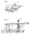
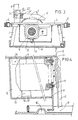
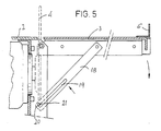
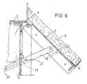
- figure 1 is a perspective view of the machine as a whole; figure 2 corresponds to a longitudinal section of same; figure 3 is a transversal section, viewed from behind the drive motor; figure 4 provides another longitudinal section view, this time on a larger scale, of the layout of the motor assembly; figures 5 and 6 similarly show in detail and on a larger scale the articulation of the mobile part of the work table.
- the machine includes a frame (1) upon which rests the work table formed of two parts, one fixed (2) and the other hinged (3), between which projects the upper edge of the cutting disc (4) with guard (5).
- the articulated part (3) of the work table has fitted to it a support rule for the piece to be cut, fitted on sliding lateral arms (7) in a manner already known.
- the frame (1) is fitted inside a tray (8), which in turn serves as coolant water container for the cutting disc (4).
- the motor (9) is mounted floating, secured by bolts (10) to a transversal partition (11), joined above to lower side of the fixed part (2) of the work table and, beneath, to the actual frame (1) of the machine.
- the motor (9) is also enclosed within a casing (12) which presents to the interior some elastic dampers (13), on which the motor (9) housing rests, in such a way as to absorb any vibrations which might arise during operation.
- the casing is in its turn secured to the respective wings (14), likewise attached to the lower side of the fixed part (2) of the table.
- the lower edge of the cutting disc (4) is submerged in the water contained in the tray (8) and is flanked by a guard plate (15) which prevents the splashing of water to the exterior.
- This same tray (8) has two pairs of projecting lugs (16), spaced at a distance from each other and from the edges of the tray such that they permit the position of the the frame (1) inside said tray (8) to be reversed.
- the tray (8) - which as has been indicated serves as a container for the cutting coolant water - has an overflow element (17) which fixes the maximum level of liquid it can contain.
- the oscillating articulated part (3) of the work table, on which the piece to be cut P is situated has two stop positions, one horizontal (figure 5), on the same plane as the fixed part (2), and the other at 450 with respect to the first (figure 6), which permits cutting of pieces directly to mitre for joining of both at right angles.
- the part (3) is nevertheless linked to the lateral diagonal braces (18), equipped with oblong openings (19) and having their respective end notches (20).
- the notches (20) can in any case set the horizontal position automatically, when the shanks of the setscrews (21) pass into them.
- Figure 3 shows assembly of the cutting disc (4) protective guard (5) by means of the vertical arm (22) which projects from the surface of the work table and which has an oblong slot (24) in which the shank of a setscrew (25) can slide.
- the guard has a notch (26) permitting it to be set in vertical position, as shown by the dotted line.
Landscapes
- Engineering & Computer Science (AREA)
- Mechanical Engineering (AREA)
- Mining & Mineral Resources (AREA)
- Sawing (AREA)
- Processing Of Stones Or Stones Resemblance Materials (AREA)
Applications Claiming Priority (2)
| Application Number | Priority Date | Filing Date | Title |
|---|---|---|---|
| ES8902017 | 1989-06-09 | ||
| ES8902017A ES2013536A6 (es) | 1989-06-09 | 1989-06-09 | Maquina tronzadora para corte de piezas planas de construccion. |
Publications (2)
| Publication Number | Publication Date |
|---|---|
| EP0402297A2 true EP0402297A2 (de) | 1990-12-12 |
| EP0402297A3 EP0402297A3 (de) | 1991-07-03 |
Family
ID=8262437
Family Applications (1)
| Application Number | Title | Priority Date | Filing Date |
|---|---|---|---|
| EP19900500050 Withdrawn EP0402297A3 (de) | 1989-06-09 | 1990-05-25 | Maschine zum Trennschneiden von flachen Bauelementen |
Country Status (2)
| Country | Link |
|---|---|
| EP (1) | EP0402297A3 (de) |
| ES (1) | ES2013536A6 (de) |
Cited By (6)
| Publication number | Priority date | Publication date | Assignee | Title |
|---|---|---|---|---|
| WO2003064093A1 (en) * | 2002-01-30 | 2003-08-07 | Turner Intellectual Property Limited | Tile cutter |
| EP1847347A2 (de) | 2006-04-21 | 2007-10-24 | Black & Decker, Inc. | Tischsäge |
| EP2754521A3 (de) * | 2003-11-06 | 2014-09-24 | Amada Company, Limited | Bandsägemaschine und Sägeblattantriebsverfahren |
| CN108136617A (zh) * | 2015-09-28 | 2018-06-08 | 赫尔曼斯·博阿达股份有限公司 | 通过浸没切割片进行液体冷却的陶瓷切割机 |
| CN111036975A (zh) * | 2019-12-27 | 2020-04-21 | 重庆市金久装饰工程有限责任公司 | 一种自动送料的铝材切割装置 |
| US10792834B2 (en) | 2017-06-05 | 2020-10-06 | Milwaukee Electric Tool Corporation | Table saw |
Family Cites Families (8)
| Publication number | Priority date | Publication date | Assignee | Title |
|---|---|---|---|---|
| US2990862A (en) * | 1955-08-04 | 1961-07-04 | Zorro D Ruben | Portable power table saw |
| US2990859A (en) * | 1957-12-24 | 1961-07-04 | Zorro D Ruben | Portable table saw |
| FR2096851A1 (de) * | 1970-07-06 | 1972-03-03 | Duchene Norbert | |
| US4198752A (en) * | 1978-09-27 | 1980-04-22 | Roper Corporation | Chain saw having anti-vibration features |
| FR2462252A1 (fr) * | 1979-07-31 | 1981-02-13 | Mecanique Generale | Machine portative pour la coupe de materiau de construction |
| FR2514278B1 (fr) * | 1981-10-14 | 1986-08-29 | Sobac | Bati pour scie circulaire diamantee |
| US4541404A (en) * | 1982-03-03 | 1985-09-17 | Dols Robert H | Tile cutting apparatus |
| EP0253032A1 (de) * | 1986-07-11 | 1988-01-20 | SOCIETE DE MECANIQUE GENERALE (SMG) Société Anonyme dite: | Konstruktionsmaterialienschneidemaschine |
-
1989
- 1989-06-09 ES ES8902017A patent/ES2013536A6/es not_active Expired - Lifetime
-
1990
- 1990-05-25 EP EP19900500050 patent/EP0402297A3/de not_active Withdrawn
Cited By (11)
| Publication number | Priority date | Publication date | Assignee | Title |
|---|---|---|---|---|
| WO2003064093A1 (en) * | 2002-01-30 | 2003-08-07 | Turner Intellectual Property Limited | Tile cutter |
| EP2754521A3 (de) * | 2003-11-06 | 2014-09-24 | Amada Company, Limited | Bandsägemaschine und Sägeblattantriebsverfahren |
| EP2754521B1 (de) | 2003-11-06 | 2015-09-23 | Amada Company, Limited | Bandsägemaschine und Sägeblattantriebsverfahren |
| EP1847347A2 (de) | 2006-04-21 | 2007-10-24 | Black & Decker, Inc. | Tischsäge |
| EP1847347A3 (de) * | 2006-04-21 | 2008-01-09 | Black & Decker, Inc. | Tischsäge |
| US8584564B2 (en) | 2006-04-21 | 2013-11-19 | Black & Decker Inc. | Table saw |
| CN108136617A (zh) * | 2015-09-28 | 2018-06-08 | 赫尔曼斯·博阿达股份有限公司 | 通过浸没切割片进行液体冷却的陶瓷切割机 |
| US10792834B2 (en) | 2017-06-05 | 2020-10-06 | Milwaukee Electric Tool Corporation | Table saw |
| US11407142B2 (en) | 2017-06-05 | 2022-08-09 | Milwaukee Electric Tool Corporation | Table saw |
| CN111036975A (zh) * | 2019-12-27 | 2020-04-21 | 重庆市金久装饰工程有限责任公司 | 一种自动送料的铝材切割装置 |
| CN111036975B (zh) * | 2019-12-27 | 2020-11-24 | 重庆市金久装饰工程有限责任公司 | 一种自动送料的铝材切割装置 |
Also Published As
| Publication number | Publication date |
|---|---|
| EP0402297A3 (de) | 1991-07-03 |
| ES2013536A6 (es) | 1990-05-01 |
Similar Documents
| Publication | Publication Date | Title |
|---|---|---|
| US4763706A (en) | Router mounting table | |
| US4163404A (en) | Power saws | |
| US5165317A (en) | Multi-use apparatus for the control of portable power tools | |
| US4531441A (en) | Combination table and miter saw | |
| US6138372A (en) | Router guide apparatus | |
| EP0370098A1 (de) | Ausziehtische für werkzeugmaschinen und verfahren zu deren aufstellung | |
| US4546804A (en) | Woodworking machine | |
| JPH06126518A (ja) | フライスヘッド | |
| AU571438B2 (en) | Tile cutting apparatus | |
| US2013778A (en) | Combination material working machine | |
| KR102151865B1 (ko) | 판재절단용 전동식 원형톱장치 | |
| JPS59134677A (ja) | 工作台 | |
| US4768570A (en) | Cutting support and guide | |
| US2973789A (en) | Panel mounted angularly adjustable tools | |
| EP0402297A3 (de) | Maschine zum Trennschneiden von flachen Bauelementen | |
| US4965964A (en) | Portable apparatus for processing marble tile | |
| EP0494039B1 (de) | Gehrungssäge mit nicht verschiebbarem Kreissägeblatt | |
| US4527602A (en) | Duplicating attachment for lathe | |
| US6390741B1 (en) | Safety guard assembly | |
| FI85347C (fi) | Universalverkbaenk. | |
| CN209207430U (zh) | 一种切割机用支撑云台 | |
| EP0368184B1 (de) | Anlage für die Nassbearbeitung, insbesondere zum Schneiden von Stein | |
| CN220761690U (zh) | 一种切割机底座四轴液压夹具 | |
| AU639249B2 (en) | Apparatus for forming shaped edges | |
| CN215746688U (zh) | 一种金相切割机 |
Legal Events
| Date | Code | Title | Description |
|---|---|---|---|
| PUAI | Public reference made under article 153(3) epc to a published international application that has entered the european phase |
Free format text: ORIGINAL CODE: 0009012 |
|
| AK | Designated contracting states |
Kind code of ref document: A2 Designated state(s): AT BE CH DE DK FR GB GR IT LI LU NL SE |
|
| PUAL | Search report despatched |
Free format text: ORIGINAL CODE: 0009013 |
|
| AK | Designated contracting states |
Kind code of ref document: A3 Designated state(s): AT BE CH DE DK FR GB GR IT LI LU NL SE |
|
| 17P | Request for examination filed |
Effective date: 19911202 |
|
| 17Q | First examination report despatched |
Effective date: 19920924 |
|
| STAA | Information on the status of an ep patent application or granted ep patent |
Free format text: STATUS: THE APPLICATION IS DEEMED TO BE WITHDRAWN |
|
| 18D | Application deemed to be withdrawn |
Effective date: 19930205 |