EP0402237A2 - Drucksiebvorrichtung - Google Patents
Drucksiebvorrichtung Download PDFInfo
- Publication number
- EP0402237A2 EP0402237A2 EP90401517A EP90401517A EP0402237A2 EP 0402237 A2 EP0402237 A2 EP 0402237A2 EP 90401517 A EP90401517 A EP 90401517A EP 90401517 A EP90401517 A EP 90401517A EP 0402237 A2 EP0402237 A2 EP 0402237A2
- Authority
- EP
- European Patent Office
- Prior art keywords
- screenplate
- screening device
- pulp
- pressurized screening
- pressurized
- Prior art date
- Legal status (The legal status is an assumption and is not a legal conclusion. Google has not performed a legal analysis and makes no representation as to the accuracy of the status listed.)
- Granted
Links
Images

Classifications
-
- D—TEXTILES; PAPER
- D21—PAPER-MAKING; PRODUCTION OF CELLULOSE
- D21D—TREATMENT OF THE MATERIALS BEFORE PASSING TO THE PAPER-MAKING MACHINE
- D21D5/00—Purification of the pulp suspension by mechanical means; Apparatus therefor
- D21D5/02—Straining or screening the pulp
- D21D5/023—Stationary screen-drums
- D21D5/026—Stationary screen-drums with rotating cleaning foils
Definitions
- the invention relates to a pressurized screening device for screening fibre pulp, especially paper pulp or the like, the pressurized screening device having a screenplate with perforations, at least one means, which is in connection with and moves relative to the screenplate, for maintaining the screenplate clean and the perforations open during screening, means for generating the relative motion between the screenplate and said at least one means for maintaining the screenplate clean and the perforations open during screening, piping means firstly for introducing fibre pulp into the pressurized screening device, secondly for conducting the accepted fibre pulp into the next process stage and thirdly for discharging the rejected pulp from the pressurized screening device preferably to be returned into the pressurized screening device, and guiding devices for turning the flow direction of the fibre pulp entering the pressurized screening device to be screened essentially parallel with the screenplate to a direction essentially perpendicular to the screenplate.
- the essential parts of the construction described above are known from a Finnish patent FI-2820.
- the construction in question is, however, a so-called centrifugal screener.
- the object of said construction is to introduce pulp to a rotor construction having uniformly bent blades, the rotor construction accelerating the pulp into a rotary motion in a manner necessary in centrifugal screeners. Accelerating of pulp into a rotary motion requires much energy. Furthermore, rotating pulp passes the perforations in the screenplate with high velocity and, therefore, the pulp fibre velocity parallel with the screenplate must abruptly slow down and turn perpendicular to the screenplate in order to pass through the perforations of the screenplate.
- the object of the present invention is to upgrade the state of art in the field, specifically the important screening stage, and thus gain several benefits in processes which utilize screening.
- the pressurized screening device according to the invention is meant to be placed at such a process stage where fibre pulp is processed the last time before entering the actual manufacturing process. Especially in the case of paper mills this means that the pressurized screening device according to the invention is placed as the last screen in the short cycle of the paper mill.
- the pressurized screening device functions immediately before the head box as the last screening stage, the incoming pulp having already been screened at least once at an earlier process stage. Therefore, there is no need to impose any high demands for the separating capacity but instead one strives to maximise the flow per unit area.
- the pressurized screening device is mainly characterized in that the guiding devices for turning the fibre pulp essentially perpendicular to the screenplate comprise an assembly having two or more compartments for guiding the flow of fibre pulp, the compartments comprising: - in lateral direction, essentially closed side walls, which are essentially parallel with the incoming flow of the pulp, - a back wall connecting those edges of the side walls which lie farmost from the screenplate and - at least two baffle blades disposed between the side walls and arranged in succession in the flow direction of fibre pulp and directed towards the screenplate, which baffle blades are designed to divide and turn the flow of the paper pulp essentially entering each compartment in a direction essentially parallel with the screenplate to a flow essentially perpendicular to the screenplate at each portion of the screenplate adjacent the compartment in question.
- the means for maintaining the screen plates clean and the perforations open can constructionally be shaped in such a way and can be positioned in the pressurized screening device so that its motion relative to the screenplate cannot generate any essential velocity component parallel with the screenplate to the pulp before fibre pulp enters the compartments on one hand and from the compartments to the perforations of the screenplate on the other hand.
- the means for maintaining the screenplate clean and the perforations open during screening has been expressly and exclusively designed for said purpose.
- the pressurized screening device 1 according to the invention and the drive mechanism has been mounted on a rigid bed 3.
- an electric motor is used as the driving mechanism 2 driving the moving parts of the pressurized screening device, for instance, via a belt transmission 4.
- the actual pressurized screening device 1 consists of a stand 5, having belt transmission 4 inside, a housing 6 on top having preferably a circular cross-section and a vertical centre line. Attached to the top of housing 6 there is an end part 7 having a pipe 8 functioning as the inlet opening for supplying fibre pulp into the pressurized screening device ( arrow T) essentially parallel with the centre line of housing 6. Housing 6 also accomodates a pipe 9 for conducting the accepted pulp to the next process stage ( arrow H) and also a pipe 10 for removing the rejected pulp from the pressurized screening device ( arrow HH). It is generally preferable to return that rejected pulp via washing stages back into the pressurized screening device through pipe 8.
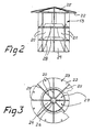
- Housing 6 of pressurized screening device 1 accommodates a perforated screen plate 11 having a conical surface with open ends and being so positioned that the centre line is coincident or parallel with the centre line of housing 6.
- Screenplate 11 comprises perforations 12 through which the accepted portion of the pulp goes from the guiding devices 13 to an annular space 14 being radially bounded by housing 6 and having connection with said pipe 9.
- Screenplate 11 is rigidly connected to the pressurized screening device 1.
- Belt transmission 4 is linked to a vertical unit 15 supported on the lower horizontal end 16 of housing 6 and comprising a bearing unit.
- a conical body 18 of the means 17 for maintaining the screenplate clean and the perforations open, later called as cleaning means, is attached to the upper end of unit 15, the actual cleaning means 17 being disposed on the lower edge thereof and being designed to move along the inner surface of screenplate 11.
- the cleaning means 17 move within an annular vertical space 19 bounded by the front edge 21 of the side walls 20 of the guiding device 13 on one hand and by the inner surface of screenplate 11 on the other hand.
- Cleaning means 17 rotate along the cylindrical inner surface of the screenplate driven by unit 15 of the driving mechanism 2.
- guiding devices 13 are rigidly supported relative to the pressurized screening device 1 by an annular horizontal flange 22 on the upper edge of housing 6.
- the horizontal flange 22 is provided with holes 23 for bolt joint.
- the horizontal flange 22 is supported by triangular bars 25 on a conical surface 24 formed by the back walls of the guiding devices 13. Said bars have been arranged to extend radially from the upper part of the cone 24 forming the back wall and being closed in its upper part 26.
- Side walls 20 which are preferably of one piece, are formed under bars 25 forming together with bars 25 several circumferentially adjacent compartments 27 whose longitudinal direction is primarily parallel to the flow direction (arrow T) of the pulp entering the pressurized screening device. This flow is turned in compartments 27 into a flow essentially perpendicular to screenplate 11 of the pressurized screening device at each compartment.
- baffle blades 28 have been disposed, arranged in succession in the vertical direction of the guiding device 13, between the side walls 20, the baffle blades being curved in the longitudinal cross-section so that their concave surface is essentially directed upwards, towards the incoming flow, whereupon in the vertical cross-section the tangent of the trailing edge of baffle blade 28 at the side edge 21 of side walls 20 is perpendicular to the screenplate (point A in figure 1).
- the edge of each blade 28, the entrance edge, which lies farmost from the front edge 21 of side walls 20, is loose from the conical surface 24 forming the back wall, and the tangent in the vertical cross-section of the baffle blade is essentially parallel with the flow of the entering fibre pulp ( point B in figure 1).
- Said tangent can be common to baffle blades 28 whereupon the entrance edges lie in the same vertical line in a given vertical cross-section. In this case, the pulp flowing forwards in compartment 27 and passing said baffle blade moves between said edge and the back wall.
- the conical surface forming the back wall extends downwards and therefore, in a horizontal cross-section, downwardly narrowing compartments 27 are formed.
- the conical surface 24 forms the last baffle blade.
- the rejected pulp goes into a space 28, which is in connection with the piping means 10, from the lower edge of screenplate 11 through an annular slot 29 between body 18 of cleaning device 17 and screenplate 11.
- Unit 15 and body 18 of cleaning device 17 are preferably placed inside the conical surface 24.
Landscapes
- Engineering & Computer Science (AREA)
- Mechanical Engineering (AREA)
- Paper (AREA)
- Electrophonic Musical Instruments (AREA)
- Push-Button Switches (AREA)
- Massaging Devices (AREA)
- Electrical Discharge Machining, Electrochemical Machining, And Combined Machining (AREA)
- Press Drives And Press Lines (AREA)
- Cosmetics (AREA)
Applications Claiming Priority (2)
| Application Number | Priority Date | Filing Date | Title |
|---|---|---|---|
| FI892735 | 1989-06-05 | ||
| FI892735A FI83892C (fi) | 1989-06-05 | 1989-06-05 | Trycksil. |
Publications (3)
| Publication Number | Publication Date |
|---|---|
| EP0402237A2 true EP0402237A2 (de) | 1990-12-12 |
| EP0402237A3 EP0402237A3 (de) | 1991-07-31 |
| EP0402237B1 EP0402237B1 (de) | 1994-12-07 |
Family
ID=8528564
Family Applications (1)
| Application Number | Title | Priority Date | Filing Date |
|---|---|---|---|
| EP90401517A Expired - Lifetime EP0402237B1 (de) | 1989-06-05 | 1990-06-05 | Drucksiebvorrichtung |
Country Status (7)
| Country | Link |
|---|---|
| US (1) | US5041213A (de) |
| EP (1) | EP0402237B1 (de) |
| AT (1) | ATE115210T1 (de) |
| CA (1) | CA2018177C (de) |
| DE (1) | DE69014719T2 (de) |
| FI (1) | FI83892C (de) |
| NO (1) | NO178408C (de) |
Cited By (1)
| Publication number | Priority date | Publication date | Assignee | Title |
|---|---|---|---|---|
| EP0931875A1 (de) * | 1998-01-22 | 1999-07-28 | COMER S.p.A. | Siebvorrichtung für Fasersuspensionen |
Families Citing this family (3)
| Publication number | Priority date | Publication date | Assignee | Title |
|---|---|---|---|---|
| DE19821447A1 (de) * | 1998-05-13 | 1999-11-18 | Fiedler Heinrich Gmbh | Vorrichtung zum Sortieren von faserstoffhaltiger Suspension |
| US6571957B1 (en) * | 2000-08-07 | 2003-06-03 | Voith Sulzer Paper Technology North America, Inc. | Screening apparatus for fiber suspension |
| DE102011079230A1 (de) * | 2011-07-15 | 2013-01-17 | Voith Patent Gmbh | Drucksortierer |
Family Cites Families (11)
| Publication number | Priority date | Publication date | Assignee | Title |
|---|---|---|---|---|
| DE34534C (de) * | E. GESSNER in Aue in Sachsen | Verbesserungen an Walk- und Waschmaschinen | ||
| US817333A (en) * | 1905-08-07 | 1906-04-10 | Hjalmar L Orrman | Centrifugal sieving apparatus. |
| US868341A (en) * | 1907-03-22 | 1907-10-15 | Andreas Hansen Holden | Centrifugal separator for wood-pulp and similar materials. |
| US1742592A (en) * | 1927-04-23 | 1930-01-07 | Haug Anton Joseph | Pulp-screening machine |
| US1856176A (en) * | 1928-09-06 | 1932-05-03 | Edward J Trimbey | Method of and apparatus for screening paper pulp |
| US2246669A (en) * | 1938-06-13 | 1941-06-24 | Cowan Elijah | Pulp screening apparatus |
| FI35151A (fi) * | 1959-05-27 | 1965-07-10 | Centrifugalsorterare för pappersmassa | |
| CA889156A (en) * | 1969-09-19 | 1971-12-28 | Cowan Ben | Screen impeller |
| US4267035A (en) * | 1979-08-27 | 1981-05-12 | The Black Clawson Company | Pressurized rotary screening apparatus |
| CA1238604A (en) * | 1983-12-12 | 1988-06-28 | Uniweld Inc. | Rotary pulp screen of the vertical pressure type having pulp stock feed at different axial positions on the screen |
| US4749475A (en) * | 1986-10-23 | 1988-06-07 | Uniweld, Inc. | Two stage rotary pulp screening device |
-
1989
- 1989-06-05 FI FI892735A patent/FI83892C/fi not_active IP Right Cessation
-
1990
- 1990-06-04 CA CA002018177A patent/CA2018177C/en not_active Expired - Fee Related
- 1990-06-05 US US07/533,433 patent/US5041213A/en not_active Expired - Fee Related
- 1990-06-05 AT AT90401517T patent/ATE115210T1/de not_active IP Right Cessation
- 1990-06-05 EP EP90401517A patent/EP0402237B1/de not_active Expired - Lifetime
- 1990-06-05 NO NO902463A patent/NO178408C/no not_active IP Right Cessation
- 1990-06-05 DE DE69014719T patent/DE69014719T2/de not_active Expired - Fee Related
Cited By (1)
| Publication number | Priority date | Publication date | Assignee | Title |
|---|---|---|---|---|
| EP0931875A1 (de) * | 1998-01-22 | 1999-07-28 | COMER S.p.A. | Siebvorrichtung für Fasersuspensionen |
Also Published As
| Publication number | Publication date |
|---|---|
| FI83892B (fi) | 1991-05-31 |
| NO178408C (no) | 1996-03-20 |
| CA2018177A1 (en) | 1990-12-05 |
| ATE115210T1 (de) | 1994-12-15 |
| NO902463D0 (no) | 1990-06-05 |
| NO178408B (no) | 1995-12-11 |
| US5041213A (en) | 1991-08-20 |
| NO902463L (no) | 1990-12-06 |
| FI892735A0 (fi) | 1989-06-05 |
| FI83892C (fi) | 1991-09-10 |
| FI892735A7 (fi) | 1990-12-06 |
| DE69014719T2 (de) | 1995-04-27 |
| CA2018177C (en) | 1999-07-27 |
| EP0402237A3 (de) | 1991-07-31 |
| DE69014719D1 (de) | 1995-01-19 |
| EP0402237B1 (de) | 1994-12-07 |
Similar Documents
| Publication | Publication Date | Title |
|---|---|---|
| US3939065A (en) | Screening device | |
| US4043919A (en) | Pressure screen with turbulence chamber means | |
| US3581903A (en) | Separator for paper pulp suspensions | |
| US3898157A (en) | Two stage pressure pulp screen device with stationary cylindrical screen | |
| US4356085A (en) | Rotary screening machine for pulp suspensions | |
| US4941970A (en) | Apparatus for dividing a suspension of fibrous cellulose pulp | |
| US5358637A (en) | Apparatus for sorting and deflaking fibrous suspensions | |
| FI66036C (fi) | Silapparat foer massauppslamning | |
| CA2018177C (en) | Pressurized screening device | |
| US4328096A (en) | Dual flow screening apparatus | |
| CA1163236A (en) | Dual flow screening apparatus | |
| US3305180A (en) | Process of pulping and defibering paper stock and apparatus therefor | |
| PL114122B1 (en) | Apparatus for straining out a liquid suspension | |
| US5186332A (en) | Paper stock screening apparatus having heavy rejects trap | |
| US6571957B1 (en) | Screening apparatus for fiber suspension | |
| EP0485153B1 (de) | Sortiervorrichtung zum Entfernen von Knoten aus einer flüssigen Suspension von Fasern und Knoten | |
| US4346007A (en) | Method at screening apparatus for cleaning the apertures in a screen plate and device for carrying out the method | |
| US3690571A (en) | Apparatus for disintegrating and separating material in fluid suspension | |
| JPS637808B2 (de) | ||
| AT408771B (de) | Sortierer zur reinigung einer faserstoffsuspension | |
| EP0726981B1 (de) | Anlage in einem drucksieb zur trennung der verunreinigungen aus einer in dem sieb eingeführten fasersuspension | |
| CN102356195B (zh) | 用于处理纤维素纸浆的结构、系统和方法 | |
| KR960015815B1 (ko) | 섬유 현탁액용 분류기 | |
| US3533505A (en) | Screening apparatus | |
| US5323913A (en) | Pressure screening apparatus with baffle |
Legal Events
| Date | Code | Title | Description |
|---|---|---|---|
| PUAI | Public reference made under article 153(3) epc to a published international application that has entered the european phase |
Free format text: ORIGINAL CODE: 0009012 |
|
| AK | Designated contracting states |
Kind code of ref document: A2 Designated state(s): AT DE FR GB SE |
|
| PUAL | Search report despatched |
Free format text: ORIGINAL CODE: 0009013 |
|
| AK | Designated contracting states |
Kind code of ref document: A3 Designated state(s): AT DE FR GB SE |
|
| 17P | Request for examination filed |
Effective date: 19911210 |
|
| 17Q | First examination report despatched |
Effective date: 19930721 |
|
| GRAA | (expected) grant |
Free format text: ORIGINAL CODE: 0009210 |
|
| AK | Designated contracting states |
Kind code of ref document: B1 Designated state(s): AT DE FR GB SE |
|
| REF | Corresponds to: |
Ref document number: 115210 Country of ref document: AT Date of ref document: 19941215 Kind code of ref document: T |
|
| REF | Corresponds to: |
Ref document number: 69014719 Country of ref document: DE Date of ref document: 19950119 |
|
| EAL | Se: european patent in force in sweden |
Ref document number: 90401517.9 |
|
| ET | Fr: translation filed | ||
| PLBE | No opposition filed within time limit |
Free format text: ORIGINAL CODE: 0009261 |
|
| STAA | Information on the status of an ep patent application or granted ep patent |
Free format text: STATUS: NO OPPOSITION FILED WITHIN TIME LIMIT |
|
| 26N | No opposition filed | ||
| PGFP | Annual fee paid to national office [announced via postgrant information from national office to epo] |
Ref country code: AT Payment date: 20000517 Year of fee payment: 11 |
|
| PGFP | Annual fee paid to national office [announced via postgrant information from national office to epo] |
Ref country code: FR Payment date: 20000518 Year of fee payment: 11 |
|
| PGFP | Annual fee paid to national office [announced via postgrant information from national office to epo] |
Ref country code: SE Payment date: 20000519 Year of fee payment: 11 |
|
| PGFP | Annual fee paid to national office [announced via postgrant information from national office to epo] |
Ref country code: GB Payment date: 20000523 Year of fee payment: 11 |
|
| PGFP | Annual fee paid to national office [announced via postgrant information from national office to epo] |
Ref country code: DE Payment date: 20000524 Year of fee payment: 11 |
|
| PG25 | Lapsed in a contracting state [announced via postgrant information from national office to epo] |
Ref country code: GB Free format text: LAPSE BECAUSE OF NON-PAYMENT OF DUE FEES Effective date: 20010605 Ref country code: AT Free format text: LAPSE BECAUSE OF NON-PAYMENT OF DUE FEES Effective date: 20010605 |
|
| PG25 | Lapsed in a contracting state [announced via postgrant information from national office to epo] |
Ref country code: SE Free format text: LAPSE BECAUSE OF NON-PAYMENT OF DUE FEES Effective date: 20010606 |
|
| GBPC | Gb: european patent ceased through non-payment of renewal fee |
Effective date: 20010605 |
|
| EUG | Se: european patent has lapsed |
Ref document number: 90401517.9 |
|
| PG25 | Lapsed in a contracting state [announced via postgrant information from national office to epo] |
Ref country code: FR Free format text: LAPSE BECAUSE OF NON-PAYMENT OF DUE FEES Effective date: 20020228 |
|
| PG25 | Lapsed in a contracting state [announced via postgrant information from national office to epo] |
Ref country code: DE Free format text: LAPSE BECAUSE OF NON-PAYMENT OF DUE FEES Effective date: 20020403 |