EP0401644B1 - Kleincontainer mit Bodenauslauf - Google Patents
Kleincontainer mit Bodenauslauf Download PDFInfo
- Publication number
- EP0401644B1 EP0401644B1 EP90110163A EP90110163A EP0401644B1 EP 0401644 B1 EP0401644 B1 EP 0401644B1 EP 90110163 A EP90110163 A EP 90110163A EP 90110163 A EP90110163 A EP 90110163A EP 0401644 B1 EP0401644 B1 EP 0401644B1
- Authority
- EP
- European Patent Office
- Prior art keywords
- small container
- clamp
- constructed
- fitting
- support
- Prior art date
- Legal status (The legal status is an assumption and is not a legal conclusion. Google has not performed a legal analysis and makes no representation as to the accuracy of the status listed.)
- Expired - Lifetime
Links
- 239000002184 metal Substances 0.000 claims description 3
- 229910052751 metal Inorganic materials 0.000 claims description 3
- XEEYBQQBJWHFJM-UHFFFAOYSA-N iron Substances [Fe] XEEYBQQBJWHFJM-UHFFFAOYSA-N 0.000 description 4
- 229910052742 iron Inorganic materials 0.000 description 3
- XLYOFNOQVPJJNP-UHFFFAOYSA-N water Substances O XLYOFNOQVPJJNP-UHFFFAOYSA-N 0.000 description 3
- 230000002349 favourable effect Effects 0.000 description 1
- 239000007788 liquid Substances 0.000 description 1
- 235000011837 pasties Nutrition 0.000 description 1
- 230000001737 promoting effect Effects 0.000 description 1
Images

Classifications
-
- B—PERFORMING OPERATIONS; TRANSPORTING
- B67—OPENING, CLOSING OR CLEANING BOTTLES, JARS OR SIMILAR CONTAINERS; LIQUID HANDLING
- B67D—DISPENSING, DELIVERING OR TRANSFERRING LIQUIDS, NOT OTHERWISE PROVIDED FOR
- B67D7/00—Apparatus or devices for transferring liquids from bulk storage containers or reservoirs into vehicles or into portable containers, e.g. for retail sale purposes
Definitions
- the invention relates to a small container with a floor outlet, an outlet fitting and a holder for the outlet fitting.
- Small containers are understood to be cubic or cylindrical containers with a capacity of 100 liters to 1000 liters, which are intended for the transport and storage of liquid, dusty, granular or pasty goods.
- the outlet fittings such as slanted seat valves, ball valves and flaps with dimensions from 1 '' to 3 '' are connected by screw or welded connection via a pipe connection at the lowest point on the small container floor, usually to a dome that is deep-drawn from the floor surface.
- valve's own weight acts as a cantilever load on the connection to the spherical cap, and especially when the small container is being transported, valve vibrations can lead to a fatigue fracture in the welded joint.
- the fittings are hung directly under the small container floor using appropriately adapted brackets. In the known small containers, a large number of different brackets are required, which are adapted to the different connection geometries of the fittings.
- the pipe only needs to be held at any freely selectable position in its longitudinal direction. Accordingly, two pipe clamps encompassing the pipe are sufficient, which are screwed with their fastening flanges to height-adjustable webs.
- the object of the invention is to provide a small container with a uniform holder for different fittings.
- the holder consists of a carrier connected to the bottom of the container and a two-part clamp which is adjustable and vertically screwed to the carrier in the axial direction of the outlet fitting, the upper part of which flanges extending upward in the axial direction the fitting has elongated holes.
- the holder can thus be adjusted both in the vertical and in the axial direction of the outlet fitting.
- the attachment is done with the help of screws. Due to the adjustability in both directions, the clamp can be adjusted with regard to the clamping location of the fitting used in each case, and there is also the possibility of fitting such fittings whose axis is against the small container axis, e.g. is inclined to hold down.
- the clamp-shaped design makes it possible to hold the fitting securely, regardless of the cross-sectional shape, whereby the most favorable position of the fitting can be selected through the setting option.
- the invention can be advantageously configured as follows.
- the carrier is designed as a U-iron which is open at the bottom and extends at least approximately in the axial direction of the fitting and has several holes in the legs of the U in the longitudinal direction, can be adjusted in the axial direction of the outlet fitting by screwing the clamp on a conveniently located hole.
- the individual holes have the advantage of higher stability instead of the design of a continuous longitudinal recess in the legs of the U-iron, which is also possible per se.
- the adjustability in the vertical direction can be made possible in a simple manner by the holes being designed as elongated holes which extend at least approximately in the vertical direction.
- the holes being designed as elongated holes which extend at least approximately in the vertical direction.
- a web connecting the two flanges is designed as a downwardly extending sheet metal provided with gripping teeth and forming the upper part of the clamp, results in a particularly good fixation with regard to the rotation of the fitting about its axis, which is particularly the case with screwed fittings , in which a loosening of the screw connection during actuation and thus leakage of the screw connection is possible, is important.
- Many fittings have transverse grooves in the body of the fitting, which make it easier to clamp them through the gripping teeth.
- the lower part of the clamp is expediently half-shell-shaped.
- the half-shell-shaped clamp part securely supports the valve body, regardless of whether it is round or polygonal, thus promoting the usability of the holder for the various valves.
- the cooperating half-clamp screw connection tabs are designed so that one of the tabs is supported against the other tab with a short angled end piece, a large and permanent clamping force is achieved during screwing.
- the small container 1 with floor outlet 2 has a socket ball valve as outlet fitting 3.
- a holder for the outlet fitting 3 consists of a support 4, which is connected to the bottom of the container 1 and is designed as a U-shaped iron, and a clamp 5, which is screwed to the support 4 so as to be adjustable in the vertical and axial directions Leg of the U holes 6, which are designed as approximately extending in the vertical direction longitudinal holes.
- the clamp 5 is formed in two parts. Its upper part 8 has upwardly extending flanges with holes 7 which extend in the axial direction of the fitting as elongated holes.
- a web 10 connecting the two flanges 9 is designed as a downwardly extending sheet metal provided with gripping teeth 11 and forming the upper part of the clamp 5.
- the lower part 12 of the clamp is half-shell-shaped. Its two screw tabs 13 are angled upward 14 in the end part, so that when screwing 15 with the screws with washer, spring washer and nuts against the screw tabs Support 16 of the upper part 8 of the clamp 5.
- the screw connection 17 consisting of a father screw, washer, spring washer and nut serves to connect the flanges 9 to the carrier 4, which is connected to the bottom of the small container 1 with a fillet weld.
- the outlet fitting 3 is screwed to the floor outlet 2.
- the upper part 8 of the clamp 5 is loosely connected to the screw connection 17, which is guided through an elongated hole 6 located in the correct place, and the lower part 12 of the clamp 5 is firmly screwed to the upper part 8 of the clamp with the screw connection 15 to the fitting, wherein the teeth 11 press into the grooves 18 of the fitting and secure them against rotation when actuated.
- the assembly is then ended by tightening the screw connection 17.
Landscapes
- Engineering & Computer Science (AREA)
- Mechanical Engineering (AREA)
- Details Of Rigid Or Semi-Rigid Containers (AREA)
- Devices For Use In Laboratory Experiments (AREA)
- Table Devices Or Equipment (AREA)
- Constitution Of High-Frequency Heating (AREA)
- Cultivation Receptacles Or Flower-Pots, Or Pots For Seedlings (AREA)
- Valve Housings (AREA)
- Clamps And Clips (AREA)
- Storage Of Web-Like Or Filamentary Materials (AREA)
- Cartons (AREA)
Description
- Die Erfindung betrifft einen Kleincontainer mit Bodenauslauf, einer Auslaufarmatur und einer Halterung für die Auslaufarmatur. - Unter Kleincontainer werden kubische oder zylindrische Behälter mit einem Fassungsvermögen von 100 Liter bis 1000 Liter verstanden, die für den Transport und für die Lagerung von flüssigen, staubförmigen, körnigen oder pastösen Gütern bestimmt sind. Die Auslaufarmaturen, wie Muffenschrägsitzventile, Kugelhähne und Klappen mit Abmessungen von 1'' bis 3'' werden durch Schraub- oder Schweißverbindung über ein Rohrverbindungsstück an der tiefsten Stelle des Kleincontainerbodens, in der Regel an einer aus der Bodenfläche tiefgezogenen Kalotte, angeschlossen. Dabei wirkt das Eigengewicht der Armaturen als Kraglast an der Verbindung zur Kalotte,und insbesondere beim Transport des Kleincontainers können Schwingungen der Armatur zum Ermüdungsbruch der Verbindungsschweißnaht führen. Um das zu verhindern, werden die Armaturen durch entsprechend angepaßte Halterungen direkt unter dem Kleincontainerboden aufgehängt. Bei den bekannten Kleincontainern wird dazu eine Vielzahl unterschiedlicher Halterungen benötigt, die den unterschiedlichen Anschlußgeometrien der Armaturen angepaßt sind.
- Bei Waschwasserbehältern für Kraftfahrzeug-Scheibenwaschanlagen ist es bekannt (DE-U-8 708 820), Pumpen zum Fördern des Waschwassers mit Haltebügeln an den Waschwasserbehälter anzuklipsen. - Ferner ist eine Haltevorrichtung für Rohrschellen und andere Rohrlager bekannt (DE-C-3 804 940), mit der Rohre in einstellbarer Höhenlage sicher fixiert werden sollen.
- Dazu braucht das Rohr nur an einer beliebigen, frei wählbaren Stelle seiner Längsrichtung gehalten zu werden. Dementsprechend genügen zwei das Rohr umfassende Rohrschellen, die mit ihren Befestigungsflanschen an höhenverstellbare Stege angeschraubt werden.
- Aufgabe der Erfindung ist es, einen Kleincontainer mit einer einheitlichen Halterung für verschiedene Armaturen anzugeben.
- Diese Aufgabe wird dadurch gelöst, daß die Halterung aus einem mit dem Boden des Containers verbundenen Träger und einer mit dem Träger in vertikaler und in axialer Richtung der Auslaufarmatur einstellbar verschraubten, zweiteilig ausgebildeten Schelle besteht, deren Oberteil nach oben erstreckende Flansche mit sich in axialer Richtung der Armatur erstrekkenden Langlöchern aufweist. Damit ist die Halterung sowohl in vertikaler als auch in axialer Richtung der Auslaufarmatur einstellbar. Die Befestigung erfolgt mit Hilfe von Schrauben. Durch die Einstellbarkeit in beiden Richtungen kann die Schelle hinsichtlich des Einspannortes der jeweils eingesetzten Armatur angepaßt werden, und es besteht auch die Möglichkeit, solche Armaturen, deren Achse gegen die Kleincontainerachse, z.B. nach unten geneigt ist, zu haltern. Die schellenförmige Ausbildung ermöglicht es, unabhängig von der jeweiligen Querschnittsform die Armatur sicher zu halten, wobei man durch die Einstellmöglichkeit die günstigste Stelle der Armatur aussuchen kann.
- Im einzelnen kann die Erfindung wie folgt vorteil haft ausgestaltet sein.
- Dadurch, daß der Träger als nach unten offenes, sich wenigstens annähernd in Achsrichtung der Armatur erstreckendes U-Eisen ausgebildet ist und in Längsrichtung mehrere Löcher in den Schenkeln des U aufweist, kann durch Anschrauben der Schelle an einem günstig liegenden Loch die Einstellbarkeit in axialer Richtung der Auslaufarmatur ermöglicht werden. Die einzelnen Löcher haben dabei anstelle der an sich auch möglichen Ausführung einer durchgehenden Längsausnehmung in den Schenkeln des U-Eisens den Vorteil höherer Stabilität.
- Die Einstellbarkeit in senkrechter Richtung kann in einfacher Weise dadurch ermöglicht werden, daß die Löcher als sich zumindest annähernd in senkrechter Richtung erstreckende Langlöcher ausgebildet sind. Natürlich ist es auch möglich, an der Schellenhalterung entsprechende, senkrecht ausgerichtete Längslöcher auszubilden oder die Halterung mehrteilig längseinstellbar zu machen.
- Dadurch, daß ein die beiden Flansche verbindender Steg als ein sich nach unten erstreckendes, mit Greifzähnen versehenes, den oberen Teil der Schelle bildendes Blech ausgebildet ist, wird eine besonders gute Fixierung hinsichtlich der Drehung der Armatur um ihre Achse bewirkt, was besonders bei verschraubten Armaturen, bei denen ein Losdrehen der Verschraubung bei der Betätigung und damit Undichtwerden der Verschraubung möglich ist, wichtig ist. Viele Armaturen weisen im Armaturenkörper Querrillen auf, die das Verklammern durch die Greifzähne erleichtern.
- Der untere Teil der Schelle ist zweckmäßig halbschalenförmig ausgebildet. Der halbschalenförmige Schellenteil legt sich sicher abstützend um den Armaturenkörper, gleichgültig, ob dieser rund oder vieleckig ist und fördert so die Einsetzbarkeit der Halterung für die verschiedenen Armaturen.
- Dadurch, daß die zusammenwirkenden Halbschellenverschraubungslappen so ausgebildet sind, daß sich einer der Lappen mit einem kurzen abgewinkelten Endstück gegen den anderen Lappen abstützt, wird beim Verschrauben eine große und bleibende Spannkraft erreicht.
- Im folgenden wird anhang einer Zeichnung ein Ausführungsbeispiel der Erfindung erläutert. Es zeigen im einzelnen
- Fig. 1
- einen Ausschnitt eines Kleincontainers mit einer Halterung und einer Armatur,
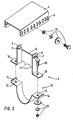
- Fig. 2
- die Halterung der Figur 1 in Explosionsdarstellung.
- Der Kleincontainer 1 mit Bodenauslauf 2 hat als Auslaufarmatur 3 einen Muffenkugelhahn. Eine Halterung für die Auslaufarmatur 3 besteht aus einem mit dem Boden des Containers 1 verbundenen, als U-Eisen ausgebildeten Träger 4 und einer mit dem Träger 4 in vertikaler und in axialer Richtung einstellbar verschraubten Schelle 5. Das U-Eisen weist in Längsrichtung in jedem Schenkel des U Löcher 6 auf, die als sich annähernd in senkrechter Richtung erstrekkende Längslöcher ausgebildet sind. Die Schelle 5 ist zweiteilig ausgebildet. Ihr Oberteil 8 hat nach oben erstreckende Flansche mit Löchern 7, die sich in Achsrichtung der Armatur als Langlöcher erstrekken. Ein die beiden Flansche 9 verbindender Steg 10 ist als ein sich nach unten erstreckendes, mit Greifzähnen 11 versehenes, den oberen Teil der Schelle 5 bildendes Blech ausgebildet. Der untere Teil 12 der Schelle ist halbschalenförmig ausgebildet. Seine beiden Verschraubungslappen 13 sind im Endteil kurz nach oben abgewinkelt 14, so daß sie sich bei Verschraubung 15 mit den Schrauben mit Unterlegscheibe, Federring und Muttern gegen die Verschraubungslappen 16 des Oberteils 8 der Schelle 5 abstützen. Die Verschraubung 17 aus Vaterschraube, Unterlegscheibe, Federring und Mutter dient zur Verbindung der Flansche 9 mit dem Träger 4. Dieser ist mit einer Kehlschweißnaht mit dem Boden des Kleincontainers 1 verbunden.
- Bei der Montage wird die Auslaufarmatur 3 mit dem Bodenauslauf 2 verschraubt. Dann wird das Oberteil 8 der Schelle 5 mit der Verschraubung 17, die durch ein an richtiger Stelle liegendes Langloch 6 geführt wird, lose verbunden und das Unterteil 12 der Schelle 5 mit dem Oberteil 8 der Schelle mit der Verschraubung 15 mit der Armatur fest verschraubt, wobei sich die Zähne 11 in die Rillen 18 der Armatur eindrücken und diese gegen Verdrehen bei Betätigung sichern. Anschließend wird die Montage durch Festziehen der Verschraubung 17 beendet.
Claims (5)
- Kleincontainer mit Bodenauslauf (2), einer Auslaufarmatur (3) und einer Halterung für die Auslaufarmatur, dadurch gekennzeichnet, daß die Halterung aus einem mit dem Boden des Containers (1) verbundenen Träger (4) und einer mit dem Träger (4) in vertikaler und in achsialer Richtung der Auslaufarmatur (3) einstellbar verschraubten, zweiteilig ausgebildeten Schelle (5) besteht, deren Oberteil (8) nach oben erstreckende Flansche (9) mit sich in achsialer Richtung der Armatur erstreckenden Langlöchern (7) aufweist.
- Kleincontainer nach Anspruch 1, dadurch gekennzeichnet, daß der Träger (4) als nach unten offenes, sich annähernd in Achsrichtung der Armatur (3) erstreckendes U-Eisen ausgebildet ist und in Längsrichtung mehrere Löcher (6) in den Schenkeln des U-Eisens aufweist, und daß die Löcher (6) als sich zumindest annähernd in senkrechter Richtung erstreckende Langlöcher ausgebildet sind.
- Kleincontainer nach Anspruch 1 oder 2, dadurch gekennzeichnet, daß ein die beiden Flansche (9) verbindender Steg (10) als ein sich nach unten erstreckendes, mit Greifzähnen versehenes Blech ausgebildet ist.
- Kleincontainer nach einem der obigen Ansprüche, dadurch gekennzeichnet, daß der untere Teil (12) der Schelle halbschalenförmig ausgebildet ist.
- Kleincontainer.nach einem der obigen Ansprüche, dadurch gekennzeichnet, daß von je zwei zusammenwirkenden Verschraubungslappen (13, 16) je einer Schellenhälfte der eine (13) am äußeren Ende kurz auf den gegenüberliegenden Verschraubungslappen (16) hin abgewinkelt ist und sich auf diesem abstützt.
Priority Applications (1)
| Application Number | Priority Date | Filing Date | Title |
|---|---|---|---|
| AT90110163T ATE89383T1 (de) | 1989-06-08 | 1990-05-29 | Kleincontainer mit bodenauslauf. |
Applications Claiming Priority (2)
| Application Number | Priority Date | Filing Date | Title |
|---|---|---|---|
| DE8907009U DE8907009U1 (de) | 1989-06-08 | 1989-06-08 | Kleincontainer mit Bodenauslauf |
| DE8907009U | 1989-06-08 |
Publications (2)
| Publication Number | Publication Date |
|---|---|
| EP0401644A1 EP0401644A1 (de) | 1990-12-12 |
| EP0401644B1 true EP0401644B1 (de) | 1993-05-12 |
Family
ID=6839907
Family Applications (1)
| Application Number | Title | Priority Date | Filing Date |
|---|---|---|---|
| EP90110163A Expired - Lifetime EP0401644B1 (de) | 1989-06-08 | 1990-05-29 | Kleincontainer mit Bodenauslauf |
Country Status (5)
| Country | Link |
|---|---|
| EP (1) | EP0401644B1 (de) |
| AT (1) | ATE89383T1 (de) |
| DE (2) | DE8907009U1 (de) |
| ES (1) | ES2042143T3 (de) |
| NO (1) | NO175583C (de) |
Family Cites Families (4)
| Publication number | Priority date | Publication date | Assignee | Title |
|---|---|---|---|---|
| GB326895A (en) * | 1928-12-29 | 1930-03-27 | Lilian Sargeaunt | An improved clamp for connecting tubular or other bodies |
| DE8708820U1 (de) * | 1987-06-25 | 1987-08-27 | Audi AG, 8070 Ingolstadt | Waschwasserbehälter für eine Kraftfahrzeug-Scheibenwaschanlage |
| US4805862A (en) * | 1987-07-30 | 1989-02-21 | Washington Suburban Sanitary Commission | Harness for supporting a meter on a fire hydrant and the combination of a meter, fire hydrant and harness |
| DE3804940C1 (de) * | 1988-02-17 | 1989-01-26 | Franz 6200 Wiesbaden De Mueller |
-
1989
- 1989-06-08 DE DE8907009U patent/DE8907009U1/de not_active Expired
-
1990
- 1990-05-29 DE DE9090110163T patent/DE59001409D1/de not_active Expired - Fee Related
- 1990-05-29 ES ES199090110163T patent/ES2042143T3/es not_active Expired - Lifetime
- 1990-05-29 EP EP90110163A patent/EP0401644B1/de not_active Expired - Lifetime
- 1990-05-29 AT AT90110163T patent/ATE89383T1/de active
- 1990-06-07 NO NO902525A patent/NO175583C/no unknown
Also Published As
| Publication number | Publication date |
|---|---|
| ES2042143T3 (es) | 1993-12-01 |
| NO175583B (no) | 1994-07-25 |
| DE59001409D1 (de) | 1993-06-17 |
| NO175583C (no) | 1994-11-02 |
| NO902525D0 (no) | 1990-06-07 |
| ATE89383T1 (de) | 1993-05-15 |
| EP0401644A1 (de) | 1990-12-12 |
| DE8907009U1 (de) | 1989-08-17 |
| NO902525L (no) | 1990-12-10 |
Similar Documents
| Publication | Publication Date | Title |
|---|---|---|
| EP0576041B1 (de) | Sanitär- und Heizungsrohrsystem, vollständig oder überwiegend bestehend aus Kunststoff | |
| DE69727402T2 (de) | Montagevorrichtung für fahrzeuganzeigen | |
| DE9401393U1 (de) | Schwingungsdämpfender Leitungshalter | |
| EP1380462A2 (de) | Befestigungsvorrichtung für Behälter | |
| DE19719301A1 (de) | Aufbauseitige Lagerung eines Stoßdämpfers | |
| EP1426233A1 (de) | Halter für einen Getränkebehälter | |
| EP0401644B1 (de) | Kleincontainer mit Bodenauslauf | |
| DE3928059C1 (en) | Vehicle anti-lock braking circuit - has sleeves containing rubber buffers for hydraulic housing mounting | |
| EP1213161A2 (de) | Anhängezugvorrichtung | |
| EP0268007A1 (de) | Vorrichtung zur Lagerung eines Führungslenkers für eine Radaufhängung eines Kraftfahrzeugs | |
| DE4327859C1 (de) | Gelenkschraubrohrschelle | |
| DE102005002889A1 (de) | Haltevorrichtung für einen Stabilisator einer Radaufhängung | |
| US20220379823A1 (en) | Tractor tool caddy | |
| DE4120780A1 (de) | Fahrzeug-lasttraeger | |
| DE19630663A1 (de) | Schraubenverbindung | |
| DE19645781C1 (de) | Befestigungsvorrichtung für eine Begasungseinrichtung | |
| EP0337414A1 (de) | Lager für Rohr-Verteilerbatterien | |
| DE1113615B (de) | Rohranbohrschelle, insbesondere fuer Versorgungsleitungen aus Kunststoff | |
| DE19514498C2 (de) | Haltevorrichtung für an Guß-, Stahl- oder Faserzementrohren anbringbare Anschlußarmaturen | |
| EP0244351B1 (de) | Lageranordnung für eine Spülkippe | |
| DE60316606T2 (de) | Scharniermontagevorrichtung für toilettenschüsseln | |
| EP0265647A1 (de) | Halterung für eine Radabdeckung | |
| DE3135042A1 (de) | "luftgefederte fahrzeugachse fuer lastkraftwagen" | |
| AT405683B (de) | Anordnung an einem membran-ausdehnungsgefäss | |
| DE9011846U1 (de) | Schienenbefestigungsset |
Legal Events
| Date | Code | Title | Description |
|---|---|---|---|
| PUAI | Public reference made under article 153(3) epc to a published international application that has entered the european phase |
Free format text: ORIGINAL CODE: 0009012 |
|
| AK | Designated contracting states |
Kind code of ref document: A1 Designated state(s): AT BE CH DE ES FR GB IT LI NL |
|
| 17P | Request for examination filed |
Effective date: 19901219 |
|
| 17Q | First examination report despatched |
Effective date: 19910524 |
|
| GRAA | (expected) grant |
Free format text: ORIGINAL CODE: 0009210 |
|
| AK | Designated contracting states |
Kind code of ref document: B1 Designated state(s): AT BE CH DE ES FR GB IT LI NL |
|
| REF | Corresponds to: |
Ref document number: 89383 Country of ref document: AT Date of ref document: 19930515 Kind code of ref document: T |
|
| ET | Fr: translation filed | ||
| REF | Corresponds to: |
Ref document number: 59001409 Country of ref document: DE Date of ref document: 19930617 |
|
| ITF | It: translation for a ep patent filed | ||
| GBT | Gb: translation of ep patent filed (gb section 77(6)(a)/1977) |
Effective date: 19930820 |
|
| REG | Reference to a national code |
Ref country code: ES Ref legal event code: FG2A Ref document number: 2042143 Country of ref document: ES Kind code of ref document: T3 |
|
| PGFP | Annual fee paid to national office [announced via postgrant information from national office to epo] |
Ref country code: DE Payment date: 19940504 Year of fee payment: 5 |
|
| PGFP | Annual fee paid to national office [announced via postgrant information from national office to epo] |
Ref country code: GB Payment date: 19940512 Year of fee payment: 5 |
|
| PGFP | Annual fee paid to national office [announced via postgrant information from national office to epo] |
Ref country code: FR Payment date: 19940517 Year of fee payment: 5 |
|
| PGFP | Annual fee paid to national office [announced via postgrant information from national office to epo] |
Ref country code: AT Payment date: 19940525 Year of fee payment: 5 |
|
| PGFP | Annual fee paid to national office [announced via postgrant information from national office to epo] |
Ref country code: NL Payment date: 19940531 Year of fee payment: 5 Ref country code: ES Payment date: 19940531 Year of fee payment: 5 |
|
| PGFP | Annual fee paid to national office [announced via postgrant information from national office to epo] |
Ref country code: BE Payment date: 19940607 Year of fee payment: 5 |
|
| PGFP | Annual fee paid to national office [announced via postgrant information from national office to epo] |
Ref country code: CH Payment date: 19940620 Year of fee payment: 5 |
|
| PG25 | Lapsed in a contracting state [announced via postgrant information from national office to epo] |
Ref country code: GB Effective date: 19950529 Ref country code: AT Effective date: 19950529 |
|
| PG25 | Lapsed in a contracting state [announced via postgrant information from national office to epo] |
Ref country code: ES Free format text: LAPSE BECAUSE OF NON-PAYMENT OF DUE FEES Effective date: 19950530 |
|
| PG25 | Lapsed in a contracting state [announced via postgrant information from national office to epo] |
Ref country code: LI Effective date: 19950531 Ref country code: CH Effective date: 19950531 Ref country code: BE Effective date: 19950531 |
|
| BERE | Be: lapsed |
Owner name: UMFORMTECHNIK HAUSACH G.M.B.H. Effective date: 19950531 |
|
| PG25 | Lapsed in a contracting state [announced via postgrant information from national office to epo] |
Ref country code: NL Effective date: 19951201 |
|
| GBPC | Gb: european patent ceased through non-payment of renewal fee |
Effective date: 19950529 |
|
| REG | Reference to a national code |
Ref country code: CH Ref legal event code: PL |
|
| NLV4 | Nl: lapsed or anulled due to non-payment of the annual fee |
Effective date: 19951201 |
|
| PG25 | Lapsed in a contracting state [announced via postgrant information from national office to epo] |
Ref country code: DE Effective date: 19960201 |
|
| PG25 | Lapsed in a contracting state [announced via postgrant information from national office to epo] |
Ref country code: FR Effective date: 19960229 |
|
| REG | Reference to a national code |
Ref country code: FR Ref legal event code: ST |
|
| REG | Reference to a national code |
Ref country code: FR Ref legal event code: ST |
|
| REG | Reference to a national code |
Ref country code: ES Ref legal event code: FD2A Effective date: 19990503 |
|
| PG25 | Lapsed in a contracting state [announced via postgrant information from national office to epo] |
Ref country code: IT Free format text: LAPSE BECAUSE OF NON-PAYMENT OF DUE FEES;WARNING: LAPSES OF ITALIAN PATENTS WITH EFFECTIVE DATE BEFORE 2007 MAY HAVE OCCURRED AT ANY TIME BEFORE 2007. THE CORRECT EFFECTIVE DATE MAY BE DIFFERENT FROM THE ONE RECORDED. Effective date: 20050529 |
|
| PLBE | No opposition filed within time limit |
Free format text: ORIGINAL CODE: 0009261 |
|
| STAA | Information on the status of an ep patent application or granted ep patent |
Free format text: STATUS: NO OPPOSITION FILED WITHIN TIME LIMIT |