EP0401171A2 - Carrier strip for powder activated driving tools - Google Patents
Carrier strip for powder activated driving tools Download PDFInfo
- Publication number
- EP0401171A2 EP0401171A2 EP90810389A EP90810389A EP0401171A2 EP 0401171 A2 EP0401171 A2 EP 0401171A2 EP 90810389 A EP90810389 A EP 90810389A EP 90810389 A EP90810389 A EP 90810389A EP 0401171 A2 EP0401171 A2 EP 0401171A2
- Authority
- EP
- European Patent Office
- Prior art keywords
- carrier strip
- setting direction
- nails
- receiving bores
- strip according
- Prior art date
- Legal status (The legal status is an assumption and is not a legal conclusion. Google has not performed a legal analysis and makes no representation as to the accuracy of the status listed.)
- Granted
Links
- 239000000843 powder Substances 0.000 title 1
- 239000011324 bead Substances 0.000 claims description 26
- 238000006073 displacement reaction Methods 0.000 abstract 1
- 230000014759 maintenance of location Effects 0.000 abstract 1
- 238000003780 insertion Methods 0.000 description 2
- 230000037431 insertion Effects 0.000 description 2
- 238000010276 construction Methods 0.000 description 1
- 230000005489 elastic deformation Effects 0.000 description 1
- 230000001771 impaired effect Effects 0.000 description 1
- 238000000034 method Methods 0.000 description 1
- 238000000926 separation method Methods 0.000 description 1
- 230000035939 shock Effects 0.000 description 1
Images
Classifications
-
- B—PERFORMING OPERATIONS; TRANSPORTING
- B25—HAND TOOLS; PORTABLE POWER-DRIVEN TOOLS; MANIPULATORS
- B25C—HAND-HELD NAILING OR STAPLING TOOLS; MANUALLY OPERATED PORTABLE STAPLING TOOLS
- B25C1/00—Hand-held nailing tools; Nail feeding devices
- B25C1/08—Hand-held nailing tools; Nail feeding devices operated by combustion pressure
- B25C1/10—Hand-held nailing tools; Nail feeding devices operated by combustion pressure generated by detonation of a cartridge
- B25C1/16—Cartridges specially adapted for impact tools; Cartridge and bolts units
-
- F—MECHANICAL ENGINEERING; LIGHTING; HEATING; WEAPONS; BLASTING
- F16—ENGINEERING ELEMENTS AND UNITS; GENERAL MEASURES FOR PRODUCING AND MAINTAINING EFFECTIVE FUNCTIONING OF MACHINES OR INSTALLATIONS; THERMAL INSULATION IN GENERAL
- F16B—DEVICES FOR FASTENING OR SECURING CONSTRUCTIONAL ELEMENTS OR MACHINE PARTS TOGETHER, e.g. NAILS, BOLTS, CIRCLIPS, CLAMPS, CLIPS OR WEDGES; JOINTS OR JOINTING
- F16B15/00—Nails; Staples
- F16B15/08—Nails; Staples formed in integral series but easily separable
-
- F—MECHANICAL ENGINEERING; LIGHTING; HEATING; WEAPONS; BLASTING
- F16—ENGINEERING ELEMENTS AND UNITS; GENERAL MEASURES FOR PRODUCING AND MAINTAINING EFFECTIVE FUNCTIONING OF MACHINES OR INSTALLATIONS; THERMAL INSULATION IN GENERAL
- F16B—DEVICES FOR FASTENING OR SECURING CONSTRUCTIONAL ELEMENTS OR MACHINE PARTS TOGETHER, e.g. NAILS, BOLTS, CIRCLIPS, CLAMPS, CLIPS OR WEDGES; JOINTS OR JOINTING
- F16B19/00—Bolts without screw-thread; Pins, including deformable elements; Rivets
- F16B19/14—Bolts or the like for shooting into concrete constructions, metal walls or the like by means of detonation-operated nailing tools
Definitions
- the invention relates to a carrier strip for powder-operated setting tools, with uniformly spaced receiving bores in which nails are slidably mounted, the nails having a head and a shaft with two spaced-apart guide disks for storing the nails in the receiving bores, the outer diameter of the head corresponds at most to the inner diameter of the receiving bores.
- a carrier strip with nails known from DE-P 38 06 624.6 enables the use of simple device-side transport and locking devices and prevents the occurrence of empty strokes of the device-side driving piston.
- the nails are held in the receiving bores of the carrier strip by using the elasticity of the carrier strip. This requires precise matching of the mounting holes and guide disks.
- the invention has for its object to provide a carrier strip that allows storage of nails without precise matching of mounting holes and guide washers, and also in the case of strong shocks or the like sudden impact, as can occur in rough construction site use, shifting the nails before setting prevented.
- At least one of the guide disks is provided with stops supporting the nails in and against the setting direction, at least the setting direction-side stop for moving the nails within the receiving bore being overcome under setting conditions.
- the stops ensure a reliable axial deflection which is not impaired by vibrations or the like support of the nails in the carrier strip, even if the diameter of the receiving bores is equal to or slightly larger than the diameter of the guide disks. Due to the functional separation of the guiding and holding function, the carrier strip does not require a precise diameter adjustment of the mounting holes with the guide washers of the nails.
- the stops are pushed radially outward by the guide disks with radial elastic deformation of the carrier strip, for example made of plastic.
- the nails with the guide disks can thus leave the carrier strip for the setting process under setting conditions.
- a stop is expediently provided for each of the guide disks.
- the stops can thus be offset from one another in the axial direction of the receiving bore in accordance with the distance between the guide disks, as a result of which the holding function of the stops is not mutually influenced, which is particularly advantageous when inserting the nails into the receiving bores.
- the stop on the setting direction is preferably provided for the guide disc on the setting direction in the setting direction and the stop lying against the setting direction is provided for the guide disc arranged against the setting direction against the setting direction.
- the stop provided in the setting direction is advantageously offset in its axial projection corresponding to the receiving bore with respect to the stop provided against the setting direction.
- the stops are preferably designed as annular beads which project into the clear width of the receiving bores and run along a normal plane to the axis of the receiving bores forms, which leads to a linear support of the guide discs.
- the annular beads can protrude radially into the clear width of the receiving bores by two or more tenths of a millimeter.
- the annular beads advantageously extend over a circumferential angle of 30 ° to 90 °. This configuration of the annular beads means that their radial protrusion into the clear width of the receiving bores can be kept small, while at the same time ensuring sufficient support for the guide disks.
- annular beads are expediently arranged in the circumferential direction of the receiving bores.
- two annular beads each forming a stop can be arranged diametrically opposite one another. While such a pair of annular beads supports the guide disk on the setting direction, another pair of annular beads can support the other guide disk against the setting direction. Both pairs of annular beads can be arranged offset from one another by 90 °. The nails are thus held evenly in the mounting holes.
- the annular beads advantageously have a sawtooth-shaped cross section in a sectional plane running along the axis of the receiving bores.
- the short sawtooth flank of the stops expediently faces the guide disks. This ensures that after insertion of the nails by sliding the guide disks along the long sawtooth flank, the guide disks are supported by the short sawtooth flank of the ring beads.
- the short sawtooth flank can extend normal to the axis of the receiving bores, which means that a correspondingly large radial dimension of the ring beads Axial support capable of absorbing force is achieved.
- Openings are advantageously provided between the annular beads provided in the opposite direction to the opposite direction of the end of the strip, the length of which runs along the receiving bore and extends from the end side directed in the opposite direction to the annular beads provided in the opposite direction.
- the parts remaining between the openings form cup-shaped fingers which are articulated on the carrier strip and can be elastically bent outwards. This is advantageous for the insertion of the nails into the receiving bores in that the guide disks can pass through the annular beads provided against the setting direction with springs open and the fingers then spring back.
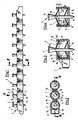
- the carrier strip 1 shown in FIG. 1 serves to hold nails 2 arranged at equal intervals from one another.
- the nails 2 are seated in receiving bores 3 of the carrier strip 1.
- the nails 2 shown overall in FIGS. 3 and 4 have a head 4 and a shaft 5.
- Two guide disks 6, 7 are seated on the shaft 5 at an axial distance from one another.
- the guide disks 6, 7 have the same diameter as the receiving bores 3 and thus ensure a concentric, axially parallel guidance of the nails 2 in the receiving bores 3.
- the guide discs 6, 7 also serve to axially hold the nails 2 in the carrier strip 1.
- the guide discs 6, 7 are supported axially against stops of the carrier strip 1 in the form of opposing ring beads 8 in the setting direction and further ring beads 9 against the setting direction.
- the annular beads 8 and 9 have a sawtooth-shaped cross section in a sectional plane running along the axis of the receiving bores 3 according to FIGS. 3 and 4.
- the shorter sawtooth flank 8a, 9a faces the guide disks 6, 7 and thus serves as a support shoulder.
- the carrier strip 1 is provided with openings 11 which are open toward the end face facing away from the setting direction and have a length L corresponding to approximately 30% of the length of the receiving bores 3.
- openings 11 which are open toward the end face facing away from the setting direction and have a length L corresponding to approximately 30% of the length of the receiving bores 3.
- the annular beads 9 facing away from the setting direction are arranged on the inside in the region of the free end.
- the parts 12 articulated on one side spring radially outwards when the nails 2 are inserted into the receiving bores 3 with the engagement of the guide disks 6 and back again for support purposes.
Landscapes
- Engineering & Computer Science (AREA)
- General Engineering & Computer Science (AREA)
- Mechanical Engineering (AREA)
- Chemical & Material Sciences (AREA)
- Combustion & Propulsion (AREA)
- Portable Nailing Machines And Staplers (AREA)
- Coating Apparatus (AREA)
- Electrostatic Spraying Apparatus (AREA)
- Treating Waste Gases (AREA)
- Pulleys (AREA)
- Vaporization, Distillation, Condensation, Sublimation, And Cold Traps (AREA)
- Mounting, Exchange, And Manufacturing Of Dies (AREA)
- Food Preservation Except Freezing, Refrigeration, And Drying (AREA)
- Basic Packing Technique (AREA)
- Automotive Seat Belt Assembly (AREA)
- Continuous Casting (AREA)
- Yarns And Mechanical Finishing Of Yarns Or Ropes (AREA)
- Finish Polishing, Edge Sharpening, And Grinding By Specific Grinding Devices (AREA)
- Powder Metallurgy (AREA)
- Registering, Tensioning, Guiding Webs, And Rollers Therefor (AREA)
- Preliminary Treatment Of Fibers (AREA)
- Automatic Assembly (AREA)
Abstract
Description
Die Erfindung betrifft einen Trägerstreifen für pulverkraftbetriebene Setzgeräte, mit in gleichmässigen Abständen zueinander angeordneten Aufnahmebohrungen, in denen Nägel verschiebbar gelagert sind, wobei die Nägel einen Kopf und einen Schaft mit zwei im Abstand zueinander angeordneten, der Lagerung der Nägel in den Aufnahmebohrungen dienenden Führungsscheiben aufweisen, wobei der Aussendurchmesser des Kopfes höchstens dem Innendurchmesser der Aufnahmebohrungen entspricht.The invention relates to a carrier strip for powder-operated setting tools, with uniformly spaced receiving bores in which nails are slidably mounted, the nails having a head and a shaft with two spaced-apart guide disks for storing the nails in the receiving bores, the outer diameter of the head corresponds at most to the inner diameter of the receiving bores.
Ein aus der DE-P 38 06 624.6 bekannter Trägerstreifen mit Nägeln ermöglicht die Verwendung einfacher geräteseitiger Transport- und Arretiereinrichtungen und unterbindet das Auftreten von Leerhüben des geräteseitigen Treibkolbens. Die Nägel sind in Aufnahmebohrungen des Trägerstreifens durch Nutzung der Elastizität des Trägerstreifens reibschlüssig gehalten. Dies erfordert eine präzise Abstimmung von Aufnahmebohrungen und Führungsscheiben.A carrier strip with nails known from DE-P 38 06 624.6 enables the use of simple device-side transport and locking devices and prevents the occurrence of empty strokes of the device-side driving piston. The nails are held in the receiving bores of the carrier strip by using the elasticity of the carrier strip. This requires precise matching of the mounting holes and guide disks.
Der Erfindung liegt die Aufgabe zugrunde, einen Trägerstreifen zu schaffen, der eine Lagerung von Nägeln ohne präzise Abstimmung von Aufnahmebohrungen und Führungsscheiben ermöglicht sowie auch bei starken Erschütterungen oder dergleichen schlagartiger Krafteinwirkung, wie sie im rauhen Baustelleneinsatz auftreten kann, ein Verschieben der Nägel vor dem Setzen verhindert.The invention has for its object to provide a carrier strip that allows storage of nails without precise matching of mounting holes and guide washers, and also in the case of strong shocks or the like sudden impact, as can occur in rough construction site use, shifting the nails before setting prevented.
Erfindungsgemäss wird dies dadurch erreicht, dass wenigstens für eine der Führungsscheiben die Nägel in und entgegen der Setzrichtung abstützende Anschläge vorgesehen sind, wobei wenigstens der setzrichtungsseitige Anschlag zum Verschieben der Nägel innerhalb der Aufnahmebohrung unter Setzbedingungen überwindbar ist.This is achieved according to the invention in that at least one of the guide disks is provided with stops supporting the nails in and against the setting direction, at least the setting direction-side stop for moving the nails within the receiving bore being overcome under setting conditions.
Vor dem Eintreten der Setzbedingungen gewährleisten die Anschläge eine durch Erschütterungen oder dergleichen Krafteinwirkung nicht beeinträchtigte zuverlässige axiale Ab stützung der Nägel im Trägerstreifen, selbst wenn der Durchmesser der Aufnahmebohrungen gleich oder geringfügig grösser als der Durchmesser der Führungsscheiben ist. Durch die funktionelle Trennung der Führungs- und Haltefunktion bedarf es bei dem Trägerstreifen keiner präzisen Durchmesserabstimmung der Aufnahmebohrungen mit den Führungsscheiben der Nägel.Before the setting conditions occur, the stops ensure a reliable axial deflection which is not impaired by vibrations or the like support of the nails in the carrier strip, even if the diameter of the receiving bores is equal to or slightly larger than the diameter of the guide disks. Due to the functional separation of the guiding and holding function, the carrier strip does not require a precise diameter adjustment of the mounting holes with the guide washers of the nails.
Durch die beim Vortreiben des geräteseitigen Treibkolbens auf die Nägel eingeleiteten Axialkräfte werden die Anschläge unter radialer elastischer Verformung des beispielsweise aus Kunststoff bestehenden Trägerstreifens von den Führungsscheiben radial nach aussen gedrängt. Die Nägel mit den Führungsscheiben können so unter Setzbedingungen den Trägerstreifen für den Setzvorgang verlassen.As a result of the axial forces introduced to the nails when the drive-side driving piston is driven forward, the stops are pushed radially outward by the guide disks with radial elastic deformation of the carrier strip, for example made of plastic. The nails with the guide disks can thus leave the carrier strip for the setting process under setting conditions.
Zweckmässig ist für jede der Führungsscheiben je ein Anschlag vorgesehen. Die Anschläge können so dem Abstand zwischen den Führungsscheiben entsprechend zueinander in Achsrichtung der Aufnahmebohrung versetzt sein, wodurch die Haltefunktion der Anschläge gegenseitig nicht beeinflusst wird, was insbesondere beim Einführen der Nägel in die Aufnahmebohrungen vorteilhaft ist. Vorzugsweise ist dabei der setzrichtungsseitige Anschlag für die setzrichtugsseitige Führungsscheibe in Setzrichtung und der entgegen der Setzrichtung liegende Anschlag für die entgegen der Setzrichtung angeordnete Führungsscheibe entgegen der Setzrichtung vorgesehen.A stop is expediently provided for each of the guide disks. The stops can thus be offset from one another in the axial direction of the receiving bore in accordance with the distance between the guide disks, as a result of which the holding function of the stops is not mutually influenced, which is particularly advantageous when inserting the nails into the receiving bores. In this case, the stop on the setting direction is preferably provided for the guide disc on the setting direction in the setting direction and the stop lying against the setting direction is provided for the guide disc arranged against the setting direction against the setting direction.
Um eine über den Umfang der Aufnahmebohrung möglichst gleichmässige Verteilung der Haltekräfte für die Nägel zu erzielen, ist der in Setzrichtung vorgesehene Anschlag mit Vorteil in seiner der Aufnahmebohrung entsprechenden Axialprojektion zu dem entgegen der Setzrichtung vorgesehenen Anschlag winkelversetzt angeordnet.In order to achieve a distribution of the holding forces for the nails that is as uniform as possible over the circumference of the receiving bore, the stop provided in the setting direction is advantageously offset in its axial projection corresponding to the receiving bore with respect to the stop provided against the setting direction.
Die Anschläge sind vorzugsweise als in die lichte Weite der Aufnahmebohrungen ragende, entlang einer Normalebene zur Achse der Aufnahmebohrungen verlaufende Ringwulste ausge bildet, was zu einer linienförmigen Abstützung der Führungsscheiben führt. Beispielsweise bei Durchmessergleichheit von Aufnahmebohrungen und Führungsscheiben können die Ringwulste zwei oder mehrere Zehntel Millimeter radial in die lichte Weite der Aufnahmebohrungen ragen.The stops are preferably designed as annular beads which project into the clear width of the receiving bores and run along a normal plane to the axis of the receiving bores forms, which leads to a linear support of the guide discs. For example, if the diameter of the receiving bores and guide disks is the same, the annular beads can protrude radially into the clear width of the receiving bores by two or more tenths of a millimeter.
Die Ringwulste erstrecken sich vorteilhaft über einen Umfangswinkel von 30° bis 90°. Durch diese Ausgestaltung der Ringwulste kann deren radiales Einragen in die lichte Weite der Aufnahmebohrungen klein gehalten werden, während gleichzeitig eine ausreichende Abstützung der Führungsscheiben gewährleistet wird.The annular beads advantageously extend over a circumferential angle of 30 ° to 90 °. This configuration of the annular beads means that their radial protrusion into the clear width of the receiving bores can be kept small, while at the same time ensuring sufficient support for the guide disks.
Um beim Ausstossen der Nägel aus dem Trägerstreifen unter Ueberwindung der Abstützkräfte der Anschläge eine zur Achse der Aufnahmebohrung schräge Krafteinwirkung zu verhindern, sind zweckmässig in Umfangsrichtung der Aufnahmebohrungen zwei oder mehrere Ringwulste angeordnet. So können beispielsweise zwei jeweils einen Anschlag bildende Ringwulste einander diametral gegenüberliegend angeordnet sein. Während ein solches Paar von Ringwulsten die setzrichtungsseitige Führungsscheibe setzrichtungsseitig abstützt, kann ein weiteres Paar Ringwulste die andere Führungsscheibe entgegen der Setzrichtung abstützen. Beide Ringwulst-Paare können zueinander um 90° versetzt angeordnet sein. Die Nägel werden so gleichmässig in den Aufnahmebohrungen gehalten.In order to prevent force acting obliquely to the axis of the receiving bore when ejecting the nails from the carrier strip while overcoming the supporting forces of the stops, two or more annular beads are expediently arranged in the circumferential direction of the receiving bores. For example, two annular beads each forming a stop can be arranged diametrically opposite one another. While such a pair of annular beads supports the guide disk on the setting direction, another pair of annular beads can support the other guide disk against the setting direction. Both pairs of annular beads can be arranged offset from one another by 90 °. The nails are thus held evenly in the mounting holes.
Vorteilhaft weisen die Ringwulste in einer entlang der Achse der Aufnahmebohrungen verlaufenden Schnittebene einen sägezahnförmigen Querschnitt auf.The annular beads advantageously have a sawtooth-shaped cross section in a sectional plane running along the axis of the receiving bores.
Zweckmässig ist die kurze Sägezahn-Flanke der Anschläge den Führungsscheiben zugewandt. Dadurch wird erreicht, dass nach dem Einführen der Nägel durch Gleiten der Führungsscheiben entlang der langen Sägezahn-Flanke die Führungsscheiben von der kurzen Sägezahn-Flanke der Ringwulste hinterstützt werden. Die kurze Sägezahn-Flanke kann sich normal zur Achse der Aufnahmebohrungen erstrecken, wodurch auch bei sehr kleiner radialer Abmessung der Ringwulste eine entsprechend kraftaufnahmefähige Axialabstützung für die Nägel erzielt wird.The short sawtooth flank of the stops expediently faces the guide disks. This ensures that after insertion of the nails by sliding the guide disks along the long sawtooth flank, the guide disks are supported by the short sawtooth flank of the ring beads. The short sawtooth flank can extend normal to the axis of the receiving bores, which means that a correspondingly large radial dimension of the ring beads Axial support capable of absorbing force is achieved.
Mit Vorteil sind zwischen den entgegen der Setzrichtung vorgesehenen Ringwulsten zu der entgegen der Setzrichtung gerichteten Stirnseite des Streifens hin offene Durchbrüche vorgesehen, deren entlang der Aufnahmebohrung verlaufende Länge sich von der entgegen der Setzrichtung gerichteten Stirnseite über die entgegen der Setzrichtung vorgesehenen Ringwulste hinaus erstreckt. Die zwischen den Durchbrüchen verbleibenden Teile bilden am Trägerstreifen angelenkte schalenförmige Finger, die elastisch nach aussen biegbar sind. Für das Einführen der Nägel in die Aufnahmebohrungen ist dies von Vorteil, indem die Führungsscheiben die entgegen der Setzrichtung vorgesehenen Ringwulste unter Ausfedern und anschliessendem Rückfedern der Finger passieren können.Openings are advantageously provided between the annular beads provided in the opposite direction to the opposite direction of the end of the strip, the length of which runs along the receiving bore and extends from the end side directed in the opposite direction to the annular beads provided in the opposite direction. The parts remaining between the openings form cup-shaped fingers which are articulated on the carrier strip and can be elastically bent outwards. This is advantageous for the insertion of the nails into the receiving bores in that the guide disks can pass through the annular beads provided against the setting direction with springs open and the fingers then spring back.
Die Erfindung wird nachstehend anhand einer Zeichnung, die ein Ausführungsbeispiel wiedergibt, näher erläutert. Es zeigen:
- Fig. 1 einen Trägerstreifen mit Nägeln, in Ansicht;
- Fig. 2 eine Teil-Ansicht des Trägerstreifens nach Fig. 1, gemäss Sichtpfeil II;
- Fig. 3 einen Schnitt durch den Trägerstreifen, gemäss Schnittverlauf III-III der Fig. 2, in verkürzter und vergrösserter Darstellung;
- Fig. 4 einen Schnitt durch den Trägerstreifen, gemäss Schnittverlauf IV-IV der Fig. 1, in vergrösserter Darstellung.
- 1 shows a carrier strip with nails, in view.
- FIG. 2 shows a partial view of the carrier strip according to FIG. 1, according to arrow II;
- 3 shows a section through the carrier strip, according to section III-III of FIG. 2, in a shortened and enlarged view;
- Fig. 4 shows a section through the carrier strip, according to section IV-IV of Fig. 1, in an enlarged view.
Der in Fig. 1 dargestellte Trägerstreifen 1 dient der Halterung zueinander in gleichmässigen Abständen angeordneter Nägel 2.The carrier strip 1 shown in FIG. 1 serves to hold
Wie der Fig. 2 zu entnehmen ist, sitzen die Nägel 2 in Aufnahmebohrungen 3 des Trägerstreifens 1. Die in den Fig. 3 und 4 gesamthaft dargestellten Nägel 2 weisen einen Kopf 4 und einen Schaft 5 auf. Auf dem Schaft 5 sitzen, in axialem Abstand zueinander, zwei Führungsscheiben 6, 7 fest. Die Führungsscheiben 6, 7 weisen denselben Durchmesser wie die Aufnahmebohrungen 3 auf und gewährleisten so eine konzentrische achsparallele Führung der Nägel 2 in den Aufnahmebohrungen 3.As can be seen from FIG. 2, the
Die Führungsscheiben 6, 7 dienen ferner der axialen Halterung der Nägel 2 im Trägerstreifen 1. Hierzu stützen sich die Führungsscheiben 6, 7 an Anschlägen des Trägerstreifens 1 in Form von einander gegenüberliegenden Ringwulsten 8 in Setzrichtung und weiterer Ringwulste 9 entgegen der Setzrichtung axial ab. Die Ringwulste 8 bzw. 9 weisen in einer entlang der Achse der Aufnahmebohrungen 3 verlaufenden Schnittebene gemäss den Fig. 3 und 4 einen sägezahnförmigen Querschnitt auf. Die kürzere Sägezahn-Flanke 8a, 9a ist den Führungsscheiben 6, 7 zugewandt und dient so als Stützschulter.The
Der Trägerstreifen 1 ist mit zu der der Setzrichtung abgewandten Stirnseite hin offenen Durchbrüchen 11 mit einer etwa 30% der Länge der Aufnahmebohrungen 3 entsprechenden Länge L versehen. An den zwischen den Durchbrüchen 11 in Umfangsrichtung stehengebliebenen fingerartigen Teilen 12 sind im Bereich des freien Endes innenseitig die der Setzrichtung abgewandten Ringwulste 9 angeordnet. Die einseitig angelenkten Teile 12 federn beim Einführen der Nägel 2 in die Aufnahmebohrungen 3 unter Eingriff der Führungsscheiben 6 radial nach aussen und zum Abstützungszwecke wieder zurück.The carrier strip 1 is provided with
Claims (10)
Applications Claiming Priority (2)
| Application Number | Priority Date | Filing Date | Title |
|---|---|---|---|
| DE3917846A DE3917846A1 (en) | 1989-06-01 | 1989-06-01 | CARRIER STRIP FOR POWDER-POWERED SETTING EQUIPMENT |
| DE3917846 | 1989-06-01 |
Publications (3)
| Publication Number | Publication Date |
|---|---|
| EP0401171A2 true EP0401171A2 (en) | 1990-12-05 |
| EP0401171A3 EP0401171A3 (en) | 1992-04-01 |
| EP0401171B1 EP0401171B1 (en) | 1994-04-27 |
Family
ID=6381827
Family Applications (1)
| Application Number | Title | Priority Date | Filing Date |
|---|---|---|---|
| EP90810389A Expired - Lifetime EP0401171B1 (en) | 1989-06-01 | 1990-05-29 | Carrier strip for powder activated driving tools |
Country Status (11)
| Country | Link |
|---|---|
| US (1) | US5046396A (en) |
| EP (1) | EP0401171B1 (en) |
| KR (1) | KR950011682B1 (en) |
| AT (1) | ATE105054T1 (en) |
| AU (1) | AU617617B2 (en) |
| CA (1) | CA2017928C (en) |
| DE (2) | DE3917846A1 (en) |
| DK (1) | DK0401171T3 (en) |
| ES (1) | ES2053160T3 (en) |
| FI (1) | FI92428C (en) |
| HU (1) | HU213990B (en) |
Cited By (1)
| Publication number | Priority date | Publication date | Assignee | Title |
|---|---|---|---|---|
| EP3674569A1 (en) * | 2018-12-27 | 2020-07-01 | Max Co., Ltd. | Connection fastener |
Families Citing this family (16)
| Publication number | Priority date | Publication date | Assignee | Title |
|---|---|---|---|---|
| CA2172141A1 (en) * | 1993-10-01 | 1995-04-13 | Stuart Edmund Blacket | Carrier tape for fasteners |
| DE19602789A1 (en) * | 1996-01-26 | 1997-07-31 | Hilti Ag | Nail strips for setting tool |
| US5811717A (en) * | 1996-08-21 | 1998-09-22 | Illinois Tool Works Inc. | Powder-actuated tool cartridge clip with position indicator mark |
| US5931622A (en) * | 1997-10-07 | 1999-08-03 | Illinois Tool Works Inc. | Fastener assembly with lateral end extension |
| DE19854573A1 (en) | 1998-11-26 | 2000-05-31 | Basf Ag | Process for post-crosslinking hydrogels with 2-oxo-tetrahydro-1,3-oxazines |
| US6814231B2 (en) | 2002-01-23 | 2004-11-09 | Illinois Tool Works Inc. | Strip of collated fasteners for fastener-driving tool |
| DE10225943A1 (en) | 2002-06-11 | 2004-01-08 | Basf Ag | Process for the preparation of esters of polyalcohols |
| US6676353B1 (en) | 2002-07-15 | 2004-01-13 | Harry M. Haytayan | Self-drilling, self-tapping screws |
| KR100549454B1 (en) * | 2002-08-22 | 2006-02-10 | 한넷텔레콤(주) | Repeater for mobile communication and method for controlling said repeater |
| US6779959B1 (en) * | 2003-04-21 | 2004-08-24 | Testo Industry Corp. | Belt of nails for nailers |
| US7654389B2 (en) * | 2004-04-14 | 2010-02-02 | Flexible Steel Lacing Company | Rivet collating system including rivet holder and method of forming the same |
| EP1736508A1 (en) | 2005-06-22 | 2006-12-27 | Basf Aktiengesellschaft | Hydrogel-forming polymers with increased permeability and high absorption capacity |
| US20080124187A1 (en) * | 2006-11-08 | 2008-05-29 | Haytayan Harry M | Self-drilling, self-tapping screw fasteners |
| DE202007005605U1 (en) * | 2007-04-18 | 2008-10-09 | Sfs Intec Holding Ag | Belt for magazineing screws and apparatus for processing the same |
| CN107206467B (en) | 2014-12-02 | 2019-07-05 | 弹性钢接头公司 | Clearing system and method for conveyer belt rivet |
| EP3501749A1 (en) * | 2017-12-20 | 2019-06-26 | HILTI Aktiengesellschaft | Fixing element strips |
Citations (3)
| Publication number | Priority date | Publication date | Assignee | Title |
|---|---|---|---|---|
| DE1625316A1 (en) * | 1967-07-20 | 1970-06-11 | Holz Elektro Feinmechanik | Bolts for push-piston shooting devices |
| DE2151051A1 (en) * | 1970-10-15 | 1972-05-25 | Omark Industries Inc | Feed device for a bolt gun |
| FR2282306A1 (en) * | 1974-08-07 | 1976-03-19 | Otalu Sa | Holding strip for rivet feeding - has seats with radial lugs for holding the rivet shanks |
Family Cites Families (4)
| Publication number | Priority date | Publication date | Assignee | Title |
|---|---|---|---|---|
| FR1600417A (en) * | 1968-08-05 | 1970-07-27 | ||
| US4106618A (en) * | 1975-12-15 | 1978-08-15 | Haytayan Harry M | Nail assemblies |
| DE3606514A1 (en) * | 1986-02-28 | 1987-09-03 | Hilti Ag | POWDER POWERED BOLT SETTING DEVICE |
| DE3806624A1 (en) * | 1988-03-02 | 1989-09-14 | Hilti Ag | CARRIER STRIPES |
-
1989
- 1989-06-01 DE DE3917846A patent/DE3917846A1/en not_active Withdrawn
-
1990
- 1990-05-29 DE DE59005503T patent/DE59005503D1/en not_active Expired - Lifetime
- 1990-05-29 ES ES90810389T patent/ES2053160T3/en not_active Expired - Lifetime
- 1990-05-29 DK DK90810389.8T patent/DK0401171T3/en active
- 1990-05-29 AT AT9090810389T patent/ATE105054T1/en not_active IP Right Cessation
- 1990-05-29 EP EP90810389A patent/EP0401171B1/en not_active Expired - Lifetime
- 1990-05-30 FI FI902691A patent/FI92428C/en not_active IP Right Cessation
- 1990-05-30 US US07/530,888 patent/US5046396A/en not_active Expired - Lifetime
- 1990-05-30 AU AU56142/90A patent/AU617617B2/en not_active Ceased
- 1990-05-30 CA CA002017928A patent/CA2017928C/en not_active Expired - Fee Related
- 1990-05-31 HU HU903283A patent/HU213990B/en not_active IP Right Cessation
- 1990-05-31 KR KR1019900007917A patent/KR950011682B1/en not_active IP Right Cessation
Patent Citations (3)
| Publication number | Priority date | Publication date | Assignee | Title |
|---|---|---|---|---|
| DE1625316A1 (en) * | 1967-07-20 | 1970-06-11 | Holz Elektro Feinmechanik | Bolts for push-piston shooting devices |
| DE2151051A1 (en) * | 1970-10-15 | 1972-05-25 | Omark Industries Inc | Feed device for a bolt gun |
| FR2282306A1 (en) * | 1974-08-07 | 1976-03-19 | Otalu Sa | Holding strip for rivet feeding - has seats with radial lugs for holding the rivet shanks |
Cited By (2)
| Publication number | Priority date | Publication date | Assignee | Title |
|---|---|---|---|---|
| EP3674569A1 (en) * | 2018-12-27 | 2020-07-01 | Max Co., Ltd. | Connection fastener |
| US11624391B2 (en) | 2018-12-27 | 2023-04-11 | Max Co., Ltd. | Connection fastener |
Also Published As
| Publication number | Publication date |
|---|---|
| FI92428C (en) | 1994-11-10 |
| FI92428B (en) | 1994-07-29 |
| KR910000304A (en) | 1991-01-29 |
| DK0401171T3 (en) | 1994-08-08 |
| AU617617B2 (en) | 1991-11-28 |
| KR950011682B1 (en) | 1995-10-07 |
| HU213990B (en) | 1997-11-28 |
| CA2017928A1 (en) | 1990-12-01 |
| US5046396A (en) | 1991-09-10 |
| ES2053160T3 (en) | 1994-07-16 |
| DE3917846A1 (en) | 1990-12-06 |
| EP0401171B1 (en) | 1994-04-27 |
| HU903283D0 (en) | 1990-10-28 |
| DE59005503D1 (en) | 1994-06-01 |
| EP0401171A3 (en) | 1992-04-01 |
| AU5614290A (en) | 1990-12-06 |
| CA2017928C (en) | 1998-04-07 |
| ATE105054T1 (en) | 1994-05-15 |
| FI902691A0 (en) | 1990-05-30 |
| HUT57397A (en) | 1991-11-28 |
Similar Documents
| Publication | Publication Date | Title |
|---|---|---|
| EP0401171A2 (en) | Carrier strip for powder activated driving tools | |
| DE3914120C2 (en) | ||
| WO2007031285A1 (en) | Device for detachably coupling two parts | |
| DE202006020765U1 (en) | Round shank chisel with chisel holder | |
| DE19827172A1 (en) | Tool holder e.g. for coupling rotating and or striking tools to hand tool machines | |
| DE2811328A1 (en) | TOOL HOLDER | |
| DE102015002712A1 (en) | Round shank chisel assembly, circlip for a round shank chisel assembly, set with a collet and circlip, and method for securing a shank chisel in a chisel holder | |
| EP3191729B1 (en) | Caliper guide device for a floating caliper brake caliper | |
| EP0570442A1 (en) | Brake shoe. | |
| EP0208839A2 (en) | Bearingbush | |
| DE4306087C2 (en) | Feed spindle mechanism with a vibration damping device | |
| DE2647703C2 (en) | Method and device for assembling friction clutches | |
| DE2459506A1 (en) | CLAW ARRANGEMENT FOR AN EXPANSION TOOL | |
| EP0764490A1 (en) | Face driver for a machine tool | |
| DE202008016454U1 (en) | Tool for polishing and fine grinding of optically effective surfaces in fine optics | |
| EP0565773B1 (en) | Quick-damping device with central centering for fixing a vehicle wheel on the axis of a balancing machine | |
| EP0780180B1 (en) | Coupling between a tool-holder and the clamping shaft of a machine tool | |
| DE2820278B2 (en) | Spring holder for the diaphragm spring in a clutch disc damper | |
| EP0198179A1 (en) | Fractional damper | |
| DE2629374A1 (en) | ROTATING TOOL CHANGER FOR PUNCHING MACHINES | |
| DE1755669B2 (en) | Fastening device for motor vehicle headlights | |
| EP0043593A1 (en) | Device for joining two flanges | |
| DE3638475A1 (en) | Eccentric drive for a rotating mass | |
| DE4003485A1 (en) | Cutting-tool coupling system - has grooves in taper boss on tool and open its rear end | |
| EP1982782B1 (en) | Collet |
Legal Events
| Date | Code | Title | Description |
|---|---|---|---|
| PUAI | Public reference made under article 153(3) epc to a published international application that has entered the european phase |
Free format text: ORIGINAL CODE: 0009012 |
|
| AK | Designated contracting states |
Kind code of ref document: A2 Designated state(s): AT BE CH DE DK ES FR GB IT LI NL SE |
|
| PUAL | Search report despatched |
Free format text: ORIGINAL CODE: 0009013 |
|
| AK | Designated contracting states |
Kind code of ref document: A3 Designated state(s): AT BE CH DE DK ES FR GB IT LI NL SE |
|
| 17P | Request for examination filed |
Effective date: 19920421 |
|
| 17Q | First examination report despatched |
Effective date: 19930405 |
|
| GRAA | (expected) grant |
Free format text: ORIGINAL CODE: 0009210 |
|
| ITF | It: translation for a ep patent filed |
Owner name: BARZANO' E ZANARDO MILANO S.P.A. |
|
| AK | Designated contracting states |
Kind code of ref document: B1 Designated state(s): AT BE CH DE DK ES FR GB IT LI NL SE |
|
| REF | Corresponds to: |
Ref document number: 105054 Country of ref document: AT Date of ref document: 19940515 Kind code of ref document: T |
|
| REF | Corresponds to: |
Ref document number: 59005503 Country of ref document: DE Date of ref document: 19940601 |
|
| ET | Fr: translation filed | ||
| GBT | Gb: translation of ep patent filed (gb section 77(6)(a)/1977) |
Effective date: 19940602 |
|
| REG | Reference to a national code |
Ref country code: ES Ref legal event code: FG2A Ref document number: 2053160 Country of ref document: ES Kind code of ref document: T3 |
|
| REG | Reference to a national code |
Ref country code: DK Ref legal event code: T3 |
|
| EAL | Se: european patent in force in sweden |
Ref document number: 90810389.8 |
|
| PLBE | No opposition filed within time limit |
Free format text: ORIGINAL CODE: 0009261 |
|
| STAA | Information on the status of an ep patent application or granted ep patent |
Free format text: STATUS: NO OPPOSITION FILED WITHIN TIME LIMIT |
|
| 26N | No opposition filed | ||
| REG | Reference to a national code |
Ref country code: GB Ref legal event code: IF02 |
|
| PGFP | Annual fee paid to national office [announced via postgrant information from national office to epo] |
Ref country code: DK Payment date: 20020514 Year of fee payment: 13 |
|
| PGFP | Annual fee paid to national office [announced via postgrant information from national office to epo] |
Ref country code: CH Payment date: 20020531 Year of fee payment: 13 |
|
| PGFP | Annual fee paid to national office [announced via postgrant information from national office to epo] |
Ref country code: BE Payment date: 20020717 Year of fee payment: 13 |
|
| PG25 | Lapsed in a contracting state [announced via postgrant information from national office to epo] |
Ref country code: BE Free format text: LAPSE BECAUSE OF NON-PAYMENT OF DUE FEES Effective date: 20030531 Ref country code: LI Free format text: LAPSE BECAUSE OF NON-PAYMENT OF DUE FEES Effective date: 20030531 Ref country code: CH Free format text: LAPSE BECAUSE OF NON-PAYMENT OF DUE FEES Effective date: 20030531 |
|
| BERE | Be: lapsed |
Owner name: *HILTI A.G. Effective date: 20030531 |
|
| PG25 | Lapsed in a contracting state [announced via postgrant information from national office to epo] |
Ref country code: DK Free format text: LAPSE BECAUSE OF NON-PAYMENT OF DUE FEES Effective date: 20031201 |
|
| REG | Reference to a national code |
Ref country code: CH Ref legal event code: PL |
|
| REG | Reference to a national code |
Ref country code: DK Ref legal event code: EBP |
|
| PG25 | Lapsed in a contracting state [announced via postgrant information from national office to epo] |
Ref country code: IT Free format text: LAPSE BECAUSE OF NON-PAYMENT OF DUE FEES Effective date: 20050529 |
|
| PGFP | Annual fee paid to national office [announced via postgrant information from national office to epo] |
Ref country code: ES Payment date: 20090605 Year of fee payment: 20 Ref country code: NL Payment date: 20090504 Year of fee payment: 20 |
|
| PGFP | Annual fee paid to national office [announced via postgrant information from national office to epo] |
Ref country code: SE Payment date: 20090512 Year of fee payment: 20 Ref country code: FR Payment date: 20090515 Year of fee payment: 20 Ref country code: DE Payment date: 20090511 Year of fee payment: 20 Ref country code: AT Payment date: 20090514 Year of fee payment: 20 |
|
| PGFP | Annual fee paid to national office [announced via postgrant information from national office to epo] |
Ref country code: GB Payment date: 20090527 Year of fee payment: 20 |
|
| REG | Reference to a national code |
Ref country code: NL Ref legal event code: V4 Effective date: 20100529 |
|
| EUG | Se: european patent has lapsed | ||
| REG | Reference to a national code |
Ref country code: ES Ref legal event code: FD2A Effective date: 20100531 |
|
| PG25 | Lapsed in a contracting state [announced via postgrant information from national office to epo] |
Ref country code: NL Free format text: LAPSE BECAUSE OF EXPIRATION OF PROTECTION Effective date: 20100529 |
|
| PG25 | Lapsed in a contracting state [announced via postgrant information from national office to epo] |
Ref country code: ES Free format text: LAPSE BECAUSE OF EXPIRATION OF PROTECTION Effective date: 20100531 |
|
| PG25 | Lapsed in a contracting state [announced via postgrant information from national office to epo] |
Ref country code: GB Free format text: LAPSE BECAUSE OF EXPIRATION OF PROTECTION Effective date: 20100528 |
|
| PG25 | Lapsed in a contracting state [announced via postgrant information from national office to epo] |
Ref country code: DE Free format text: LAPSE BECAUSE OF EXPIRATION OF PROTECTION Effective date: 20100529 |