EP0401046B1 - Crossmixing dual auger system - Google Patents
Crossmixing dual auger system Download PDFInfo
- Publication number
- EP0401046B1 EP0401046B1 EP90306022A EP90306022A EP0401046B1 EP 0401046 B1 EP0401046 B1 EP 0401046B1 EP 90306022 A EP90306022 A EP 90306022A EP 90306022 A EP90306022 A EP 90306022A EP 0401046 B1 EP0401046 B1 EP 0401046B1
- Authority
- EP
- European Patent Office
- Prior art keywords
- auger
- developer
- toner
- developer material
- roll
- Prior art date
- Legal status (The legal status is an assumption and is not a legal conclusion. Google has not performed a legal analysis and makes no representation as to the accuracy of the status listed.)
- Expired - Lifetime
Links
Images


Classifications
-
- G—PHYSICS
- G03—PHOTOGRAPHY; CINEMATOGRAPHY; ANALOGOUS TECHNIQUES USING WAVES OTHER THAN OPTICAL WAVES; ELECTROGRAPHY; HOLOGRAPHY
- G03G—ELECTROGRAPHY; ELECTROPHOTOGRAPHY; MAGNETOGRAPHY
- G03G15/00—Apparatus for electrographic processes using a charge pattern
- G03G15/06—Apparatus for electrographic processes using a charge pattern for developing
- G03G15/08—Apparatus for electrographic processes using a charge pattern for developing using a solid developer, e.g. powder developer
- G03G15/09—Apparatus for electrographic processes using a charge pattern for developing using a solid developer, e.g. powder developer using magnetic brush
-
- G—PHYSICS
- G03—PHOTOGRAPHY; CINEMATOGRAPHY; ANALOGOUS TECHNIQUES USING WAVES OTHER THAN OPTICAL WAVES; ELECTROGRAPHY; HOLOGRAPHY
- G03G—ELECTROGRAPHY; ELECTROPHOTOGRAPHY; MAGNETOGRAPHY
- G03G15/00—Apparatus for electrographic processes using a charge pattern
- G03G15/06—Apparatus for electrographic processes using a charge pattern for developing
- G03G15/08—Apparatus for electrographic processes using a charge pattern for developing using a solid developer, e.g. powder developer
- G03G15/0822—Arrangements for preparing, mixing, supplying or dispensing developer
-
- G—PHYSICS
- G03—PHOTOGRAPHY; CINEMATOGRAPHY; ANALOGOUS TECHNIQUES USING WAVES OTHER THAN OPTICAL WAVES; ELECTROGRAPHY; HOLOGRAPHY
- G03G—ELECTROGRAPHY; ELECTROPHOTOGRAPHY; MAGNETOGRAPHY
- G03G2215/00—Apparatus for electrophotographic processes
- G03G2215/08—Details of powder developing device not concerning the development directly
- G03G2215/0802—Arrangements for agitating or circulating developer material
- G03G2215/0816—Agitator type
- G03G2215/0819—Agitator type two or more agitators
Definitions
- the invention relates generally to an electrophotographic printing machine and, more particularly, to a development system which includes a dual auger assembly for mixing the developer.
- an electrophotographic printing machine includes a photoconductive member which is charged to a substantially uniform potential to sensitize the surface thereof.
- the charged portion of the photoconductive member is exposed to a light image of an original document being reproduced.
- the image is developed by bringing a developer material into contact therewith.
- the developer material comprises toner particles adhering triboelectrically to carrier granules.
- the toner particles are attracted to the latent image from the carrier granules to form a powder image on the photoconductive member which is subsequently transferred to a copy sheet.
- the copy sheet is heated to permanently affix the powder image thereto in image configuration.
- a preferred system for accomplishing the crossmixing function is the use of a dual auger system to transport the toner in two directions and achieve a toner interchange between augers. Dual auger systems are disclosed, for example, in the following prior art documents.
- U.S. Patent No. 4,274,362 to Beck et al discloses magnetic brush mixing augers made of twisted strips of aluminum sheet metal with smooth axial edges.
- the auger members are located in the sump portion of a developing pan where they circulate, distribute and intermix dry toner.
- a dispensing system evenly distributes regular amounts of toner while the copier is operable.
- U.S. Patent No. 4,056,076 to Smith discloses a crossmixing system for mixing and charging multicomponent developer in a circulating development system of an electrostatographic processor.
- a pair of parallel passive crossmixers are used as mixing devices and a single active crossmixer is used as a blending (triboelectric charging) device.
- U.S. Patent No. 4,146,323 to Forward et al discloses an auger for a development system comprised of an elongated twisted strip of sheet metal with helically contoured edges. As toner is dispensed, fresh toner is added to the developer from a toner dispenser directly above a crossmixer to keep the toner concentration at a high level.
- U. S. Patent 4,478,512 to Zoltner assigned to Xerox Corporation, discloses a developer system in which a pair of augers mix newly dispensed toner with denuded carrier particles and returns the mixture into a developer sump.
- US-A-4,576,466 discloses a developing system having a primary spiral screw (5) for conveying developer (including at least toner) in one direction with respect to the width of an area to be developed, and a secondary spiral screw (16) arranged for receiving developer from the primary spiral screw via an apertured receptable (13) and for conveying the developer in a direction opposite to the conveyance direction of the primary signal screw. Both screws (5,6) are horizontally oriented. Developer is conveyed to a magnetic developer sleeve (2) by an agitator (4) having blades 11.
- the present invention provides a development system including a developer roll adapted for depositing developer material on an imaging surface having an electrostatic latent image thereon, a dual auger system for mixing said developer material and transferring mixed developer material to said developer roll, said dual auger system comprising a first auger aligned in a horizontal plane and adapted to mix and supply developer material to said developer roll, a second auger, adjacent to said first auger and positioned along a non-horizontal plane, adjacent ends of said first and second augers being separated by a vertical distance, said augers having a plurality of developer material transport communication apertures at said auger ends whereby developer material is transported from one auger to the other by gravitational forces, characterised in that the first auger is located in a horizontal plane and the second auger is located in a non-horizontal plane.
- FIG. 1 is a side view, in section, of a xerographic reproduction machine incorporating a dual auger mixing assembly in accordance with the present invention.
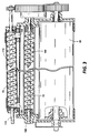
- FIG. 2 is an enlarged side view of the developer assembly of the machine shown in FIG. 1.
- FIG. 3 is a top view of the developer assembly of the machine shown in FIG. 1.
- FIG. 4 is top view schematic representation of the developer material transfer between augers.
- FIG. 5 is a side view schematic representation of the developer material transfer between the augers.
- FIG. 1 of the drawings there is shown a xerographic type reproduction machine 8 incorporating a dual auger mixing assembly in accordance with the present invention, designated generally by the numeral 10.
- Machine 8 has a suitable frame (not shown) on which the machine xerographic components are operatively supported.
- the machine xerographic components include a recording member, shown here in the form of a rotatable photoreceptor 14.
- photoreceptor 14 comprises a drum having a photoconductive surface 16.
- a charge corotron 18 for placing a uniform charge on the photoconductive surface 16 of photoreceptor 14; an exposure station 22 where the previously charged photoconductive surface 16 is exposed to image rays of a document 9 being copied or reproduced; development station 24 where the latent electrostatic image created on photoconductive surface 16 is developed by toner; and transfer detack corotrons 28 and 30 for assisting transfer of the developed image to a suitable copy substrate material such as a copy sheet 32 brought forward in timed relation with the developed image on photoconductive surface 16. Residual toner is removed from the drum surface at cleaning station 34.
- Copy sheets 32 are brought forward to the transfer area by feed roll pair 40, sheet guides 42, 43 serving to guide the sheet through an approximately 180° turn prior to the transfer area. Following transfer, the sheet 32 is carried forward to a fusing station 48 where the toner image is fixed by fusing roll 49. After fusing, the copy sheet 32 is discharged to an output tray.
- a transparent platen 50 supports the document 9 as the document is moved past a scan point 52 by a constant velocity type transport 54.
- scan point 52 is in effect a scan line extending across the width of platen 50 at a desired point along the platen where the document is scanned line by line as the document is moved along platen 50 by transport 54.
- Transport 54 has input and output document feed roll pairs 55, 56, respectively, on each side of scan point 52 for moving document 9 across platen 50 at a predetermined speed.
- Exposure lamp 58 is provided to illuminate a strip-like area of platen 50 at scan point 52. The image rays from the document line scanned are transmitted by a gradient index fiber lens array 60 to exposure station 22 to expose the photoconductive surface 16 of the moving photoreceptor 14.
- Developer station 24 includes a developer housing 65 in which a toner dispensing cartridge 66 is rotatably mounted so as to dispense toner particles downward into a sump area occupied by the dual auger mixing assembly 70 of the present invention.
- Assembly 70 includes a pair of rotatably mounted augers 72, 74; further details of the construction and operation of assembly 70 are provided below.
- a magnetic brush developer roll 80 is disposed in predetermined operative relation to the photoconductive surface 16 of photoreceptor 14, the length of developing roll 80 being equal to or slightly greater than the width of photoconductive surface 16, with the axis of roll 80 parallel to the axis of photoreceptor 14.
- Developer roll 80 has a plurality of stationary magnet assemblies 81 ( Figure 2) disposed within a rotatable cylinder or sleeve 75, sleeve 75 being rotatably journaled for rotation in the opposing sides of developer housing 65. Magnet assemblies 81 are arranged so that as sleeve 75 rotates, developer is attracted to the exterior surface of sleeve 75 to form a brush-like layer 82 on sleeve 75. Rotation of sleeve 75 carries the developer brush 82 into developing relation with the photoconductive surface 16 of photoreceptor 14 to develop the latent electrostatic image therein.
- FIGS. 2 and 3 show an end view and top view of the developer assembly.
- Figures 4 and 5 show the toner transfer betweens auger from a top and side view perspective, respectively.
- Auger 72 having arcuate segments 104 is mounted on horizontal shaft 100 which is driven by motor means (not shown) in a counterclockwise direction.
- Supported beneath auger 72 is a trough 106 extending the length of the auger.
- Auger 74 having arcuate segments 114, is mounted on inclined shaft 116 and driven by appropriate motor means in a clockwise direction.
- the configuration of shaft 116 is that the auger has an uphill end (Figure 2 out of the page) and a downhill end ( Figure 2 into the page).
- Auger 74 is contained within a cylinder 118 enclosed except for toner transfer openings 120, 122 at both ends.
- the downhill end of auger 74 with transfer opening 120 is positioned adjacent, but lower than, one end of auger 72 and receives developer from the auger via gravity feed.
- the developer is transferred from auger 72 to auger 74 by gravitational force acting on the toner.
- Auger 74 then mixes the developer and carries it uphill.
- the developer then falls into sump 110 or is again picked up by auger 72 via the higher opening 122 at the uphill end.
- auger 72 is angled upward at an angle of approximately 1°.
- a suitable controller 89 is provided for operating the various components of machine 8 in predetermined timed relation with one another to produce copies.
- machine 8 is actuated by a suitable start control button.
- the document to be copied is then inserted into the nip of document transport roll pair 55, 56 which carries the document across platen 50.
- controller 89 in response to the signal from the detector, starts feed roll pair 40 to advance the copy sheet 32 forward in timed relation with the document 9 as the document is transported across platen 50 and past scan point 52 by document transport 54.
- the document image developed on the photoconductive surface 16 of photoreceptor 14 is transferred to copy sheet 32 as the copy sheet moves through the transfer area. Following transfer, the copy sheet 32 passes to fusing station 48 where the image is fixed.
- Auger 72 continually mixes the fresh toner with the denuded carrier particles and existing developer. As the auger 72 rotates in a counterclockwise direction, and with arcuate segments 104 having an orientation as shown, the mixture is conveyed from right to left in Figure 4 and into the page in Figure 5. The mixture then transfers into the auger 74 system, which carries the developer uphill to the retransfer point. The system is thus constantly ensuring that freshly added toner is constantly being mixed into the existing developer.
- the dual auger crossmixing system accomplishes inter-auger developer transfer by a construction which utilizes the forces of gravity to accomplish the transfer at each auger end.
- the augers can be spaced physically further apart than is possible with the prior art systems. Because of the "drop distance" between each auger end, no developer buildup is experienced at either end.
Description
- The invention relates generally to an electrophotographic printing machine and, more particularly, to a development system which includes a dual auger assembly for mixing the developer.
- Generally, an electrophotographic printing machine includes a photoconductive member which is charged to a substantially uniform potential to sensitize the surface thereof. The charged portion of the photoconductive member is exposed to a light image of an original document being reproduced. This records an electrostatic latent image on the photoconductive member corresponding to the informational areas contained within the original document. After the electrostatic latent image is formed on the photoconductive member, the image is developed by bringing a developer material into contact therewith. Generally, the developer material comprises toner particles adhering triboelectrically to carrier granules. The toner particles are attracted to the latent image from the carrier granules to form a powder image on the photoconductive member which is subsequently transferred to a copy sheet. Finally, the copy sheet is heated to permanently affix the powder image thereto in image configuration.
- As the toner particles are depleted from the developer material, it is necessary to dispense additional toner particles into the developer mixture. The newly added toner is typically mixed in some manner with the denuded carrier particles and unused developer material. Various prior art devices have been devised to accomplish the mixing function. A preferred system for accomplishing the crossmixing function is the use of a dual auger system to transport the toner in two directions and achieve a toner interchange between augers. Dual auger systems are disclosed, for example, in the following prior art documents. U.S. Patent No. 4,274,362 to Beck et al discloses magnetic brush mixing augers made of twisted strips of aluminum sheet metal with smooth axial edges. In a developing unit, the auger members are located in the sump portion of a developing pan where they circulate, distribute and intermix dry toner. A dispensing system evenly distributes regular amounts of toner while the copier is operable.
- U.S. Patent No. 4,056,076 to Smith, assigned to Xerox Corporation, discloses a crossmixing system for mixing and charging multicomponent developer in a circulating development system of an electrostatographic processor. A pair of parallel passive crossmixers are used as mixing devices and a single active crossmixer is used as a blending (triboelectric charging) device.
- U.S. Patent No. 4,146,323 to Forward et al, assigned to Xerox Corporation, discloses an auger for a development system comprised of an elongated twisted strip of sheet metal with helically contoured edges. As toner is dispensed, fresh toner is added to the developer from a toner dispenser directly above a crossmixer to keep the toner concentration at a high level.
- U. S. Patent 4,478,512 to Zoltner, assigned to Xerox Corporation, discloses a developer system in which a pair of augers mix newly dispensed toner with denuded carrier particles and returns the mixture into a developer sump.
- U.S. Patent 3,999,514 to Abbott et al describes a supply and return auger system in which the augers are rotated at different flute and pitch related speeds which ensure equal flow through the auger.
- U.S. Patent 3,664,299 to Shaler et al discloses still another dual auger mixing system.
- US-A-4,576,466 discloses a developing system having a primary spiral screw (5) for conveying developer (including at least toner) in one direction with respect to the width of an area to be developed, and a secondary spiral screw (16) arranged for receiving developer from the primary spiral screw via an apertured receptable (13) and for conveying the developer in a direction opposite to the conveyance direction of the primary signal screw. Both screws (5,6) are horizontally oriented. Developer is conveyed to a magnetic developer sleeve (2) by an agitator (4) having blades 11.
- These prior art patents described above are representative of the dual auger crossmixing type of system. The common characteristic of these systems is that the axis of each auger pair lie essentially in the same horizontal plane with developer exchange between each auger taking place at end locations. A problem with this inter-auger transfer is that the developer is exchanged by a sideways pushing application which requires that the augers be physically close to each other. For some systems, this proximity requirement may present a space or geometry problem. A second difficulty with this "push" inter-auger transfer is the tendency for the developer to "bunch up" at the transfer end, sometimes resulting in toner spilling over into other areas of the developer housing unless specific seals are placed at strategic locations. It is an object of the present invention to enable these problems to be overcome.
- The present invention provides a development system including a developer roll adapted for depositing developer material on an imaging surface having an electrostatic latent image thereon, a dual auger system for mixing said developer material and transferring mixed developer material to said developer roll, said dual auger system comprising a first auger aligned in a horizontal plane and adapted to mix and supply developer material to said developer roll, a second auger, adjacent to said first auger and positioned along a non-horizontal plane, adjacent ends of said first and second augers being separated by a vertical distance, said augers having a plurality of developer material transport communication apertures at said auger ends whereby developer material is transported from one auger to the other by gravitational forces, characterised in that the first auger is located in a horizontal plane and the second auger is located in a non-horizontal plane.
- By way of example, an embodiment of the invention will be described with reference to the accompanying drawings, in which:
- FIG. 1 is a side view, in section, of a xerographic reproduction machine incorporating a dual auger mixing assembly in accordance with the present invention.
- FIG. 2 is an enlarged side view of the developer assembly of the machine shown in FIG. 1.
- FIG. 3 is a top view of the developer assembly of the machine shown in FIG. 1.
- FIG. 4 is top view schematic representation of the developer material transfer between augers.
- FIG. 5 is a side view schematic representation of the developer material transfer between the augers.
- Referring to FIG. 1 of the drawings, there is shown a xerographic type reproduction machine 8 incorporating a dual auger mixing assembly in accordance with the present invention, designated generally by the numeral 10. Machine 8 has a suitable frame (not shown) on which the machine xerographic components are operatively supported. Briefly, and as will be familiar to those skilled in the art, the machine xerographic components include a recording member, shown here in the form of a
rotatable photoreceptor 14. In the exemplary arrangement shown,photoreceptor 14 comprises a drum having aphotoconductive surface 16. Operatively disposed about the periphery ofphotoreceptor 14 are acharge corotron 18 for placing a uniform charge on thephotoconductive surface 16 ofphotoreceptor 14; anexposure station 22 where the previously chargedphotoconductive surface 16 is exposed to image rays of adocument 9 being copied or reproduced;development station 24 where the latent electrostatic image created onphotoconductive surface 16 is developed by toner; and transferdetack corotrons copy sheet 32 brought forward in timed relation with the developed image onphotoconductive surface 16. Residual toner is removed from the drum surface atcleaning station 34. -
Copy sheets 32 are brought forward to the transfer area byfeed roll pair 40,sheet guides sheet 32 is carried forward to afusing station 48 where the toner image is fixed byfusing roll 49. After fusing, thecopy sheet 32 is discharged to an output tray. - A
transparent platen 50 supports thedocument 9 as the document is moved past ascan point 52 by a constantvelocity type transport 54. As will be understood,scan point 52 is in effect a scan line extending across the width ofplaten 50 at a desired point along the platen where the document is scanned line by line as the document is moved alongplaten 50 bytransport 54.Transport 54 has input and output documentfeed roll pairs scan point 52 for movingdocument 9 acrossplaten 50 at a predetermined speed.Exposure lamp 58 is provided to illuminate a strip-like area ofplaten 50 atscan point 52. The image rays from the document line scanned are transmitted by a gradient indexfiber lens array 60 toexposure station 22 to expose thephotoconductive surface 16 of the movingphotoreceptor 14. -
Developer station 24 includes adeveloper housing 65 in which atoner dispensing cartridge 66 is rotatably mounted so as to dispense toner particles downward into a sump area occupied by the dualauger mixing assembly 70 of the present invention.Assembly 70 includes a pair of rotatably mountedaugers assembly 70 are provided below. - Continuing with the description of the developing
station 24, a magneticbrush developer roll 80 is disposed in predetermined operative relation to thephotoconductive surface 16 ofphotoreceptor 14, the length of developingroll 80 being equal to or slightly greater than the width ofphotoconductive surface 16, with the axis ofroll 80 parallel to the axis ofphotoreceptor 14.Developer roll 80 has a plurality of stationary magnet assemblies 81 (Figure 2) disposed within a rotatable cylinder orsleeve 75,sleeve 75 being rotatably journaled for rotation in the opposing sides ofdeveloper housing 65.Magnet assemblies 81 are arranged so that assleeve 75 rotates, developer is attracted to the exterior surface ofsleeve 75 to form a brush-like layer 82 onsleeve 75. Rotation ofsleeve 75 carries thedeveloper brush 82 into developing relation with thephotoconductive surface 16 ofphotoreceptor 14 to develop the latent electrostatic image therein. - Turning now to a more detailed description of the
developer station 24, and particularly theauger mixing assembly 70, Figures 2 and 3 show an end view and top view of the developer assembly. Figures 4 and 5 show the toner transfer betweens auger from a top and side view perspective, respectively. Auger 72 havingarcuate segments 104 is mounted onhorizontal shaft 100 which is driven by motor means (not shown) in a counterclockwise direction. Supported beneathauger 72 is atrough 106 extending the length of the auger. Supported aboveauger 72 ispickoff baffle 107 having a series ofports 108 extending therethrough permitting toner fromhousing 66 to be dispensed through the ports in a steady flow downward into the mixingassembly area sump 110 where it is then picked up by the exterior surface ofsleeve 75 to form thetoner brush 82. Auger 74, havingarcuate segments 114, is mounted oninclined shaft 116 and driven by appropriate motor means in a clockwise direction. The configuration ofshaft 116 is that the auger has an uphill end (Figure 2 out of the page) and a downhill end (Figure 2 into the page).Auger 74 is contained within acylinder 118 enclosed except fortoner transfer openings auger 74 with transfer opening 120 is positioned adjacent, but lower than, one end ofauger 72 and receives developer from the auger via gravity feed. The developer is transferred fromauger 72 to auger 74 by gravitational force acting on the toner.Auger 74 then mixes the developer and carries it uphill. The developer then falls intosump 110 or is again picked up byauger 72 via thehigher opening 122 at the uphill end. In preferred embodiment for a 36 inch wide system,auger 72 is angled upward at an angle of approximately 1°. - A
suitable controller 89 is provided for operating the various components of machine 8 in predetermined timed relation with one another to produce copies. In operation, machine 8 is actuated by a suitable start control button. The document to be copied is then inserted into the nip of documenttransport roll pair platen 50. As the leading edge of the document reaches a detector,controller 89, in response to the signal from the detector, startsfeed roll pair 40 to advance thecopy sheet 32 forward in timed relation with thedocument 9 as the document is transported acrossplaten 50 andpast scan point 52 bydocument transport 54. The document image developed on thephotoconductive surface 16 ofphotoreceptor 14 is transferred to copysheet 32 as the copy sheet moves through the transfer area. Following transfer, thecopy sheet 32 passes to fusingstation 48 where the image is fixed. - As latent images are formed, and developer and toner depleted, fresh toner is dispensed as
dispenser cartridge 66 rotates.Auger 72 continually mixes the fresh toner with the denuded carrier particles and existing developer. As theauger 72 rotates in a counterclockwise direction, and witharcuate segments 104 having an orientation as shown, the mixture is conveyed from right to left in Figure 4 and into the page in Figure 5. The mixture then transfers into theauger 74 system, which carries the developer uphill to the retransfer point. The system is thus constantly ensuring that freshly added toner is constantly being mixed into the existing developer. The dual auger crossmixing system accomplishes inter-auger developer transfer by a construction which utilizes the forces of gravity to accomplish the transfer at each auger end. By allowing the force of gravity to act on the developer as it exits an augers end, and in combination with appropriate side baffles to direct developer travel, the augers can be spaced physically further apart than is possible with the prior art systems. Because of the "drop distance" between each auger end, no developer buildup is experienced at either end.
Claims (4)
- A development system including a developer roll (80) adapted for depositing developer material on an imaging surface (16) having an electrostatic latent image thereon, a dual auger system for mixing said developer material and transferring mixed developer to said developer roll, said dual auger system comprising a first auger (72) adapted to mix and supply developer material to said developer roll, a second auger (74), adjacent to said first auger, the adjacent ends of said first and second auger being separated by a vertical distance, and toner transport communication apertures (120, 122) at said auger ends whereby toner is transported from one auger to the other by gravitational forces, characterised in that the first auger (72) is located in a horizontal plane and the second auger (74) is located in a non-horizontal plane.
- The development system of claim 1, wherein an apertured trough-like member (106) is positioned beneath said first auger and wherein said second auger is enclosed within a cylinder (118) having toner transport apertures (120, 122) at both ends.
- The development system of claim 1 or 2, wherein said second auger is inclined at an angle of approximately 1° with respect to the horizontal plane of said first auger.
- A dual auger magnetic brush development system wherein developer material is supplied to a rotating magnet brush roll, the system comprising
a first supply auger (72) having a length at least as great as said magnetic brush roll (80), said first auger positioned along a horizontal plane and adapted to transport developer material in a first direction so as to supply said material to said magnetic brush roll,
a second crossmixing auger (74) rotating, in use, in a direction opposite said first auger, and
developer material transport apertures (120, 122), characterised in that the second cross-mixing auger (74) is substantially the same length as said first auger and positioned at an angle with respect to said first auger so that one end is lower than the adjacent end of said first auger while the other end is higher than the respective other end of said first auger, and in that developer material is transported, in use, by gravity from said one end of the first auger to the adjacent end of said second auger, the second auger transporting the developer material uphill to the other end where the toner is transferred by gravity feed to the said other end of said first auger.
Applications Claiming Priority (2)
| Application Number | Priority Date | Filing Date | Title |
|---|---|---|---|
| US360809 | 1989-06-02 | ||
| US07/360,809 US4978997A (en) | 1989-06-02 | 1989-06-02 | Crossmixing dual auger system |
Publications (3)
| Publication Number | Publication Date |
|---|---|
| EP0401046A2 EP0401046A2 (en) | 1990-12-05 |
| EP0401046A3 EP0401046A3 (en) | 1992-05-20 |
| EP0401046B1 true EP0401046B1 (en) | 1995-03-29 |
Family
ID=23419487
Family Applications (1)
| Application Number | Title | Priority Date | Filing Date |
|---|---|---|---|
| EP90306022A Expired - Lifetime EP0401046B1 (en) | 1989-06-02 | 1990-06-01 | Crossmixing dual auger system |
Country Status (5)
| Country | Link |
|---|---|
| US (1) | US4978997A (en) |
| EP (1) | EP0401046B1 (en) |
| JP (1) | JPH03163479A (en) |
| CA (1) | CA2017264C (en) |
| DE (1) | DE69018126T2 (en) |
Families Citing this family (9)
| Publication number | Priority date | Publication date | Assignee | Title |
|---|---|---|---|---|
| JPH05127537A (en) * | 1991-11-08 | 1993-05-25 | Fujitsu Ltd | Developing device |
| US5257077A (en) * | 1992-01-31 | 1993-10-26 | Xerox Corporation | Toner dispensing apparatus for a xerographic reproduction machine |
| US5519470A (en) * | 1994-03-04 | 1996-05-21 | Xerox Corporation | Cross mixing paddle wheel |
| US5510881A (en) * | 1994-11-18 | 1996-04-23 | Xerox Corporation | Positive push development auger |
| KR0122124Y1 (en) * | 1995-05-30 | 1998-12-01 | 김광호 | Alternating device for a developer in printer |
| US6580881B2 (en) | 2001-10-04 | 2003-06-17 | Lexmark International, Inc. | Method of detecting waste toner in a container of an image forming apparatus |
| US7426361B2 (en) * | 2005-09-01 | 2008-09-16 | Eastman Kodak Company | Developer mixing apparatus having four ribbon blenders |
| JP5168631B2 (en) * | 2008-03-11 | 2013-03-21 | 株式会社リコー | Developing device and image forming apparatus |
| US20130051861A1 (en) * | 2011-08-22 | 2013-02-28 | Alan E. Rapkin | Angled magnetic auger for a developer station |
Family Cites Families (9)
| Publication number | Priority date | Publication date | Assignee | Title |
|---|---|---|---|---|
| US2028745A (en) * | 1933-04-01 | 1936-01-28 | Wallace M Hendrick | Apparatus for bituminous mixing |
| US3664299A (en) * | 1970-12-07 | 1972-05-23 | Eg & G Inc | Electrostatic recording paper toner section |
| US4056076A (en) * | 1975-04-24 | 1977-11-01 | Xerox Corporation | Developer mixing system |
| US3999514A (en) * | 1975-09-29 | 1976-12-28 | International Business Machines Corporation | Magnetic brush developer |
| US4146323A (en) * | 1977-06-29 | 1979-03-27 | Xerox Corporation | Auger for a development system |
| US4274362A (en) * | 1979-12-05 | 1981-06-23 | Pitney Bowes, Inc. | Magnetic brush mixing augers |
| JPS58163968A (en) * | 1982-03-24 | 1983-09-28 | Konishiroku Photo Ind Co Ltd | Developing device |
| US4478512A (en) * | 1983-05-11 | 1984-10-23 | Xerox Corporation | Toner cartridge for use in an electrophotographic printing machine |
| US5006893A (en) * | 1987-12-18 | 1991-04-09 | Minolta Camera Kabushiki Kaisha | Image forming apparatus with improved toner replenishment |
-
1989
- 1989-06-02 US US07/360,809 patent/US4978997A/en not_active Expired - Fee Related
-
1990
- 1990-05-22 CA CA002017264A patent/CA2017264C/en not_active Expired - Fee Related
- 1990-05-26 JP JP2136939A patent/JPH03163479A/en active Pending
- 1990-06-01 DE DE69018126T patent/DE69018126T2/en not_active Expired - Fee Related
- 1990-06-01 EP EP90306022A patent/EP0401046B1/en not_active Expired - Lifetime
Also Published As
| Publication number | Publication date |
|---|---|
| CA2017264C (en) | 1994-09-20 |
| DE69018126D1 (en) | 1995-05-04 |
| JPH03163479A (en) | 1991-07-15 |
| EP0401046A3 (en) | 1992-05-20 |
| EP0401046A2 (en) | 1990-12-05 |
| DE69018126T2 (en) | 1995-11-09 |
| CA2017264A1 (en) | 1990-12-02 |
| US4978997A (en) | 1990-12-18 |
Similar Documents
| Publication | Publication Date | Title |
|---|---|---|
| EP1533665B1 (en) | Image forming apparatus and image forming method having three agitating and conveying elements for toner in a developing unit | |
| JP3246682B2 (en) | Toner distribution device for electrophotographic copier | |
| US5758238A (en) | Auger configuration for eliminating auger mark print defect | |
| EP0401046B1 (en) | Crossmixing dual auger system | |
| US4965639A (en) | Toner supply cartridge for reproduction and printing machines | |
| US4996565A (en) | Developer material mixing apparatus | |
| US5937252A (en) | Trickle port between two augers in a developer housing | |
| JP2981019B2 (en) | Toner supply cartridge | |
| US6510304B2 (en) | Auger for magnetic materials with specific use for developer transport in elelctrographic printing systems | |
| US5519470A (en) | Cross mixing paddle wheel | |
| JP3505110B2 (en) | Developing device | |
| US4872036A (en) | Developing apparatus | |
| JPH04198966A (en) | Image forming device | |
| JPH05127519A (en) | Developing device | |
| JP2600238B2 (en) | Developing device | |
| JP2707248B2 (en) | Developing device | |
| JPH071407B2 (en) | Development device | |
| JP3795596B2 (en) | Development device | |
| JPH1020653A (en) | Developing device | |
| JPH063961A (en) | Developing device | |
| JP2536026Y2 (en) | Dry electrophotographic equipment | |
| JPH07271162A (en) | Image forming device | |
| JP2767786B2 (en) | Developing device | |
| JPS62156686A (en) | Cleaning device | |
| JPH10142942A (en) | Developing device |
Legal Events
| Date | Code | Title | Description |
|---|---|---|---|
| PUAI | Public reference made under article 153(3) epc to a published international application that has entered the european phase |
Free format text: ORIGINAL CODE: 0009012 |
|
| AK | Designated contracting states |
Kind code of ref document: A2 Designated state(s): DE FR GB |
|
| PUAL | Search report despatched |
Free format text: ORIGINAL CODE: 0009013 |
|
| AK | Designated contracting states |
Kind code of ref document: A3 Designated state(s): DE FR GB |
|
| 17P | Request for examination filed |
Effective date: 19921105 |
|
| 17Q | First examination report despatched |
Effective date: 19930805 |
|
| GRAA | (expected) grant |
Free format text: ORIGINAL CODE: 0009210 |
|
| AK | Designated contracting states |
Kind code of ref document: B1 Designated state(s): DE FR GB |
|
| ET | Fr: translation filed | ||
| REF | Corresponds to: |
Ref document number: 69018126 Country of ref document: DE Date of ref document: 19950504 |
|
| PLBE | No opposition filed within time limit |
Free format text: ORIGINAL CODE: 0009261 |
|
| STAA | Information on the status of an ep patent application or granted ep patent |
Free format text: STATUS: NO OPPOSITION FILED WITHIN TIME LIMIT |
|
| 26N | No opposition filed | ||
| PGFP | Annual fee paid to national office [announced via postgrant information from national office to epo] |
Ref country code: GB Payment date: 19980526 Year of fee payment: 9 |
|
| PGFP | Annual fee paid to national office [announced via postgrant information from national office to epo] |
Ref country code: DE Payment date: 19980608 Year of fee payment: 9 |
|
| PGFP | Annual fee paid to national office [announced via postgrant information from national office to epo] |
Ref country code: FR Payment date: 19980609 Year of fee payment: 9 |
|
| PG25 | Lapsed in a contracting state [announced via postgrant information from national office to epo] |
Ref country code: GB Free format text: LAPSE BECAUSE OF NON-PAYMENT OF DUE FEES Effective date: 19990601 |
|
| PG25 | Lapsed in a contracting state [announced via postgrant information from national office to epo] |
Ref country code: FR Free format text: THE PATENT HAS BEEN ANNULLED BY A DECISION OF A NATIONAL AUTHORITY Effective date: 19990630 |
|
| GBPC | Gb: european patent ceased through non-payment of renewal fee |
Effective date: 19990601 |
|
| PG25 | Lapsed in a contracting state [announced via postgrant information from national office to epo] |
Ref country code: DE Free format text: LAPSE BECAUSE OF NON-PAYMENT OF DUE FEES Effective date: 20000503 |
|
| REG | Reference to a national code |
Ref country code: FR Ref legal event code: ST |