EP0400200B1 - Linear motion bearing - Google Patents
Linear motion bearing Download PDFInfo
- Publication number
- EP0400200B1 EP0400200B1 EP89114473A EP89114473A EP0400200B1 EP 0400200 B1 EP0400200 B1 EP 0400200B1 EP 89114473 A EP89114473 A EP 89114473A EP 89114473 A EP89114473 A EP 89114473A EP 0400200 B1 EP0400200 B1 EP 0400200B1
- Authority
- EP
- European Patent Office
- Prior art keywords
- bearing
- linear motion
- carriage
- track
- single piece
- Prior art date
- Legal status (The legal status is an assumption and is not a legal conclusion. Google has not performed a legal analysis and makes no representation as to the accuracy of the status listed.)
- Expired - Lifetime
Links
Images




Classifications
-
- F—MECHANICAL ENGINEERING; LIGHTING; HEATING; WEAPONS; BLASTING
- F16—ENGINEERING ELEMENTS AND UNITS; GENERAL MEASURES FOR PRODUCING AND MAINTAINING EFFECTIVE FUNCTIONING OF MACHINES OR INSTALLATIONS; THERMAL INSULATION IN GENERAL
- F16C—SHAFTS; FLEXIBLE SHAFTS; ELEMENTS OR CRANKSHAFT MECHANISMS; ROTARY BODIES OTHER THAN GEARING ELEMENTS; BEARINGS
- F16C29/00—Bearings for parts moving only linearly
- F16C29/04—Ball or roller bearings
- F16C29/06—Ball or roller bearings in which the rolling bodies circulate partly without carrying load
- F16C29/0633—Ball or roller bearings in which the rolling bodies circulate partly without carrying load with a bearing body defining a U-shaped carriage, i.e. surrounding a guide rail or track on three sides
- F16C29/0635—Ball or roller bearings in which the rolling bodies circulate partly without carrying load with a bearing body defining a U-shaped carriage, i.e. surrounding a guide rail or track on three sides whereby the return paths are provided as bores in a main body of the U-shaped carriage, e.g. the main body of the U-shaped carriage is a single part with end caps provided at each end
- F16C29/0638—Ball or roller bearings in which the rolling bodies circulate partly without carrying load with a bearing body defining a U-shaped carriage, i.e. surrounding a guide rail or track on three sides whereby the return paths are provided as bores in a main body of the U-shaped carriage, e.g. the main body of the U-shaped carriage is a single part with end caps provided at each end with balls
- F16C29/0642—Ball or roller bearings in which the rolling bodies circulate partly without carrying load with a bearing body defining a U-shaped carriage, i.e. surrounding a guide rail or track on three sides whereby the return paths are provided as bores in a main body of the U-shaped carriage, e.g. the main body of the U-shaped carriage is a single part with end caps provided at each end with balls with four rows of balls
- F16C29/0645—Ball or roller bearings in which the rolling bodies circulate partly without carrying load with a bearing body defining a U-shaped carriage, i.e. surrounding a guide rail or track on three sides whereby the return paths are provided as bores in a main body of the U-shaped carriage, e.g. the main body of the U-shaped carriage is a single part with end caps provided at each end with balls with four rows of balls with load directions in O-arrangement
-
- F—MECHANICAL ENGINEERING; LIGHTING; HEATING; WEAPONS; BLASTING
- F16—ENGINEERING ELEMENTS AND UNITS; GENERAL MEASURES FOR PRODUCING AND MAINTAINING EFFECTIVE FUNCTIONING OF MACHINES OR INSTALLATIONS; THERMAL INSULATION IN GENERAL
- F16C—SHAFTS; FLEXIBLE SHAFTS; ELEMENTS OR CRANKSHAFT MECHANISMS; ROTARY BODIES OTHER THAN GEARING ELEMENTS; BEARINGS
- F16C29/00—Bearings for parts moving only linearly
- F16C29/04—Ball or roller bearings
- F16C29/06—Ball or roller bearings in which the rolling bodies circulate partly without carrying load
- F16C29/0602—Details of the bearing body or carriage or parts thereof, e.g. methods for manufacturing or assembly
- F16C29/0604—Details of the bearing body or carriage or parts thereof, e.g. methods for manufacturing or assembly of the load bearing section
- F16C29/0607—Details of the bearing body or carriage or parts thereof, e.g. methods for manufacturing or assembly of the load bearing section of parts or members for retaining the rolling elements, i.e. members to prevent the rolling elements from falling out of the bearing body or carriage
-
- F—MECHANICAL ENGINEERING; LIGHTING; HEATING; WEAPONS; BLASTING
- F16—ENGINEERING ELEMENTS AND UNITS; GENERAL MEASURES FOR PRODUCING AND MAINTAINING EFFECTIVE FUNCTIONING OF MACHINES OR INSTALLATIONS; THERMAL INSULATION IN GENERAL
- F16C—SHAFTS; FLEXIBLE SHAFTS; ELEMENTS OR CRANKSHAFT MECHANISMS; ROTARY BODIES OTHER THAN GEARING ELEMENTS; BEARINGS
- F16C29/00—Bearings for parts moving only linearly
- F16C29/08—Arrangements for covering or protecting the ways
- F16C29/084—Arrangements for covering or protecting the ways fixed to the carriage or bearing body movable along the guide rail or track
-
- F—MECHANICAL ENGINEERING; LIGHTING; HEATING; WEAPONS; BLASTING
- F16—ENGINEERING ELEMENTS AND UNITS; GENERAL MEASURES FOR PRODUCING AND MAINTAINING EFFECTIVE FUNCTIONING OF MACHINES OR INSTALLATIONS; THERMAL INSULATION IN GENERAL
- F16C—SHAFTS; FLEXIBLE SHAFTS; ELEMENTS OR CRANKSHAFT MECHANISMS; ROTARY BODIES OTHER THAN GEARING ELEMENTS; BEARINGS
- F16C2322/00—Apparatus used in shaping articles
- F16C2322/39—General buildup of machine tools, e.g. spindles, slides, actuators
Definitions
- the present invention relates to anti-friction linear motion bearings and, more particularly, to rolling element retainers for use therein.
- Linear motion bearings are well known in the art and are used extensively in a wide variety of machines, machine tools, and other equipment where one part is to be moved longitudinally with respect to another.
- These bearings may comprise an inverted U-shaped bearing carriage mounted astride a modified I-beam or T-beam shaped rail.
- One or two pairs of tracks and returns are provided in the carriage for a plurality of recirculating rolling elements, such as for example balls or rollers. These rolling elements travel alternately through load bearing tracks and return tracks to provide movement along the rail with minimum friction.
- End caps are located on either end of the carriage and usually are provided with turnarounds formed therein for transferring the recirculating rolling elements from load bearing tracks to return tracks.
- the turnarounds comprise a semi-toroidal shaped track connecting a load track to a return track.
- an inner guide is provided to smooth the movement of the rolling elements around the curved position from the load track to the return track and to prevent the rolling elements from bunching up in the turns.
- These end caps are usually formed out of plastic material using molds which form the curved tracks of the turnaround integral with the end cap.
- the inner guides are usually molded in a separate operation and inserted into the proper position in the end cap during the assembly of the bearing.
- the inner guides may be formed to be installed in only one orientation to provide adequate lubrication to the tracks. See, for example, U.S. Patent No. 4,743,124 to Blaurock (Fig. 9, items 36, 37). These inner guides can be easily inverted during assembly resulting in premature operational failure due to inadequate lubrication.
- Rolling element retainers are generally of two types. In one type, half of the retainer is incorporated into each end cap and interlocks with the opposite retainer and end cap in the middle of the bearing carriage when the bearing is assembled. See, U.S. Patent Nos. 4,743,124 to Blaurock; 4,420,193 and 4,376,557 to Teramachi et al. These types of bearings are inherently difficult to mold. Further, assembly is made more difficult by the need to use special equipment to load the recirculating rolling elements into the tracks.
- the other type of retainer is formed as a separate structure and interlocks into the end caps for support. See, U.S. Patent Nos. 4,502,737 to Osawa (Fig. 2, item 13) and 4,582,369 to Itoh (Figs. 8-11, item 14 and Fig. 11, item 22). These bearings are easier to mold or fabricate than the first mentioned bearings however, they also present difficulties in assembly. More specifically, the retainer must be held in place until the recirculating rolling elements are inserted and both end caps are secure.
- a rolling element retainer substantially supported on a bearing carriage of a linear motion bearing.
- An inner guide is integrally formed on both ends of the retainer and fits into the balance of the turnaround track formed in the inner surfaces of each end cap.
- the integral rolling element retainer and inner guides is easily molded as a single piece and eliminates the need to separately mold individual inner guides.
- the integral structure is generally formed from a flexible material and is removably attached to the bearing carriage by means of protrusions which fit into recesses in the bearing carriage.
- the rolling element retainer may also be provided with at least one projection along its longitudinal length on the side facing the inner surface of the bearing carriage. The projection(s) fit into corresponding slots formed in the bearing carriage and serve to provide further support for the integral rolling element retainer and inner guides structure.
- Such a unique design for the retainer and inner guides allows for considerable ease of assembly of the linear motion bearing and reduces the number of small parts associated with the use of separate inner guides.
- assembly of a linear motion bearing in accordance with the present invention can be accomplished by simply snapping an integral retainer and inner guides structure on each inside surface of the bearing carriage, installing one end cap on the bearing carriage, turning the carriage, open end up, and dropping in the rolling elements, and placing the final end cap in place.
- an inverted U-shaped bearing carriage 20 having four load tracks 22 and four return tracks 24 which combine to form two pairs of recirculating tracks for a plurality of rolling elements, in this case balls 26.
- the inner guides 30 are formed on the ends of the retainer structure 28 so as to be positioned between the openings of the load tracks 22 and return tracks 24 in the bearing carriage 20. These inner guides 30 serve to prevent the balls 26 from bunching up as they move between the load tracks 22 and the return tracks 24 when the linear motion bearing is in operation.
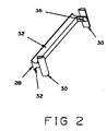
- the integral retainer and inner guides 28 in accordance with one embodiment of the present invention is shown in FIGS. 2 and 3.
- the structure has a T-shaped cross section and has a portion of the load tracks 32 formed in its lower surfaces. This configuration serves to retain the balls in the load tracks 22 of the bearing carriage 20 while providing access for the balls 26 to contact the rail 34.
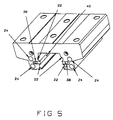
- the retainer and inner guides 28 is substantially supported on the bearing carriage 20 by means of protrusions 36 formed on the ends of the retainer structure. These protrusions 36 engage in recesses 38 formed in the ends of the bearing carriage 20. To facilitate ease of assembly, these protrusions 36 may be angled as shown in FIG. 3.
- Longitudinal support may be provided by forming projections 44 along the inside surface of the retainer and inner guides structure 28 which abuts the bearing carriage 20.
- projections 44 fits into a groove 40 formed in the inside surface of the bearing carriage 20 and serves to inhibit flexing of the integral retainer and inner guides 28.
- the retainer and inner guides structure is preferably formed of a flexible material to facilitate ease of fabrication and assembly of the finished linear motion bearing.
- the structure in accordance with the present invention can be readily molded out of plastic material using conventional molding techniques. The invention however is not limited to such materials of construction and also can be practiced using relatively non-flexible materials such as stainless steel or aluminum.
- an integral lubrication system can be incorporated into the linear motion bearing to provide lubricant directly into the load tracks 22 and/or return tracks 24 without requiring disassembly of the entire bearing.
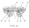
- a suitable lubrication system is shown generally in FIGS. 4 and 6.
- an end cap 46 is provided with a network of channels 48 for conducting lubricant from fitting 50 to inner guides 52.
- These inner guides 52 are also integrally formed with the retainer 28 and are further provided with a lubrication channel 54 and lubrication openings 56, which openings provide access directly into the semi-toroidal turnaround tracks 58 formed in the end cap 46.
- lubricant can be introduced from outside the linear motion bearing directly into the turnaround tracks 58 where it is picked up by the recirculating balls 26 as they travel through the turnaround tracks 58.
- the inner guides 30, 52 are integrally formed on the retainer and inner guides structure 28 so as to be positioned between the load tracks 22 and the return tracks 24 on either side of the bearing carriage 20. These inner guides 30, 52 project out from the bearing carriage 20 and interfit into indentations 60 formed in the end cap 46 and are aligned with the axes of the turnaround tracks 58 when the end caps are installed on the bearing carriage 20. Thus, when the end cap 46 and the integral retainer and inner guides structure 28 are assembled on the bearing carriage 20 a plurality of complete recirculating tracks are formed in the bearing.
- Assembly of the overall linear motion bearing is greatly simplified using the present invention.
- prior art systems required positioning a number of small pieces, and, in some configurations, special equipment to load the recirculating rolling elements into the tracks in the bearing carriage.
- assembly of the completed linear motion bearing requires minimal steps, parts and no special equipment.
- Assembly is accomplished by fitting a pair of integral retainer and inner guides 28 onto the bearing carriage 20 and then installing a single end cap 46 as shown in FIG. 7.
- the partially assembled bearing carriage 20 is then turned upright with the open face pointing upwards.
- a plurality of recirculating balls 26 are then easily inserted into the load tracks 22 and the return tracks 24.
- Assembly is completed by installing the remaining end cap onto the bearing carriage 20.
- the few balls 26 necessary to fill the total recirculating tracks can be maintained in the remaining end cap by applying a small quantity of lubricant or grease to hold them in place until the end cap 46 is securely installed.
- a sealing means 62 can be added to the linear motion bearing to further protect access to the recirculating tracks.
- One embodiment of such a sealing means 62 is shown in FIG. 8 and comprises two end portions 64 interconnected by flexible, self adjusting longitudinal sections 66.
- the end portions 64 bolt securely to the end caps 46 of the linear motion bearing and stretch longitudinal sections 66 to adjustably fit along the bottom of the bearing carriage 20. These longitudinal sections serve to further protect the exposed load tracks 22 from external contamination during operation of the linear motion bearing.
- the sealing means 62 can be fabricated from a wide variety of materials including plastics and metals.
- the seal incorporates metal stiffers 68 in the end portion 64 in order to give the seal further rigidity and sealing protection.
Landscapes
- Engineering & Computer Science (AREA)
- General Engineering & Computer Science (AREA)
- Mechanical Engineering (AREA)
- Bearings For Parts Moving Linearly (AREA)
Description
- The present invention relates to anti-friction linear motion bearings and, more particularly, to rolling element retainers for use therein.
- Linear motion bearings are well known in the art and are used extensively in a wide variety of machines, machine tools, and other equipment where one part is to be moved longitudinally with respect to another. These bearings may comprise an inverted U-shaped bearing carriage mounted astride a modified I-beam or T-beam shaped rail. One or two pairs of tracks and returns are provided in the carriage for a plurality of recirculating rolling elements, such as for example balls or rollers. These rolling elements travel alternately through load bearing tracks and return tracks to provide movement along the rail with minimum friction. End caps are located on either end of the carriage and usually are provided with turnarounds formed therein for transferring the recirculating rolling elements from load bearing tracks to return tracks. The turnarounds comprise a semi-toroidal shaped track connecting a load track to a return track. At the center of the semi-toroid, an inner guide is provided to smooth the movement of the rolling elements around the curved position from the load track to the return track and to prevent the rolling elements from bunching up in the turns. These end caps are usually formed out of plastic material using molds which form the curved tracks of the turnaround integral with the end cap. However, it is difficult to design a mold to provide an inner guide integral with the end caps. In fact, the inner guides are usually molded in a separate operation and inserted into the proper position in the end cap during the assembly of the bearing. These separately molded inner guides are extremely small and easily misaligned or even overlooked during assembly. Further, where the linear motion bearings incorporate an integral lubrication system, the inner guides may be formed to be installed in only one orientation to provide adequate lubrication to the tracks. See, for example, U.S. Patent No. 4,743,124 to Blaurock (Fig. 9,
items 36, 37). These inner guides can be easily inverted during assembly resulting in premature operational failure due to inadequate lubrication. - When the recirculating rolling elements are in the load bearing track area of the bearing carriage, they are moveably held within the track by a rolling element retainer. This structure facilitates assembly and disassembly of the linear motion bearing by preventing the rolling elements in the load bearing track from falling out when the bearing carriage is removed from the rail. Rolling element retainers are generally of two types. In one type, half of the retainer is incorporated into each end cap and interlocks with the opposite retainer and end cap in the middle of the bearing carriage when the bearing is assembled. See, U.S. Patent Nos. 4,743,124 to Blaurock; 4,420,193 and 4,376,557 to Teramachi et al. These types of bearings are inherently difficult to mold. Further, assembly is made more difficult by the need to use special equipment to load the recirculating rolling elements into the tracks.
- The other type of retainer is formed as a separate structure and interlocks into the end caps for support. See, U.S. Patent Nos. 4,502,737 to Osawa (Fig. 2, item 13) and 4,582,369 to Itoh (Figs. 8-11, item 14 and Fig. 11, item 22). These bearings are easier to mold or fabricate than the first mentioned bearings however, they also present difficulties in assembly. More specifically, the retainer must be held in place until the recirculating rolling elements are inserted and both end caps are secure.
- From the European Patent Application EP-A-137 042 there is known a linear motion bearing as it is defined by the preamble portion of claim 1. The known linear motion bearing does not offer the possibility to attach the single piece structures onto the inner surface of the bearing carriage without the use of any other parts of the linear motion bearing.
- Accordingly, it is an object of the present invention to provide a linear motion bearing which overcomes the problems relating the manufacture and assembly of the inner guides and the rolling element retainer.
- It is another object of the present invention to provide a linear motion bearing which is easier to assemble and has fewer parts.
- It is a further object of the present invention to provide a linear motion bearing wherein the end caps, inner guides and rolling element retainers are easily molded using less complex molds than those required by the prior art.
- Further, it is an object of the present invention to provide a linear motion bearing that can be easily assembled by hand without the need for special equipment.
- According to the present invention, there is provided a rolling element retainer substantially supported on a bearing carriage of a linear motion bearing. An inner guide is integrally formed on both ends of the retainer and fits into the balance of the turnaround track formed in the inner surfaces of each end cap.
- The integral rolling element retainer and inner guides is easily molded as a single piece and eliminates the need to separately mold individual inner guides. The integral structure is generally formed from a flexible material and is removably attached to the bearing carriage by means of protrusions which fit into recesses in the bearing carriage. The rolling element retainer may also be provided with at least one projection along its longitudinal length on the side facing the inner surface of the bearing carriage. The projection(s) fit into corresponding slots formed in the bearing carriage and serve to provide further support for the integral rolling element retainer and inner guides structure.
- Such a unique design for the retainer and inner guides allows for considerable ease of assembly of the linear motion bearing and reduces the number of small parts associated with the use of separate inner guides. For example, assembly of a linear motion bearing in accordance with the present invention can be accomplished by simply snapping an integral retainer and inner guides structure on each inside surface of the bearing carriage, installing one end cap on the bearing carriage, turning the carriage, open end up, and dropping in the rolling elements, and placing the final end cap in place.
- There is no need for special equipment to load the rolling elements and no small individual inner guides to insert. Furthermore, the molding of the integral retainer and inner guides structure as a single unit avoids the need to form and install the inner guides separately, a tedious and labor intensive process.
- The above and other objects, features and advantages of this invention will be apparent in the following detailed description of preferred embodiments, especially when taken in conjunction with the accompanying drawings, wherein:
- FIG. 1 is a perspective view of a bearing carriage with integral retainer and inner guides in accordance with one embodiment of the present invention using balls as the rolling element;
- FIG. 2 is a perspective view of one embodiment of an integral retainer and inner guides;
- FIG. 3 is a side view of one embodiment of an integral retainer and inner guides;
- FIG. 4 is a perspective view of an integral retainer and inner guides adapted for longitudinal support and internal lubrication;
- FIG. 5 is a perspective view of the bearing carriage without the integral retainer and inner guides installed;
- FIG. 6 is a perspective view of an end cap in accordance with one embodiment of the present invention having an integral lubrication system;
- FIG. 7 is a perspective view of a partially assembled linear motion bearing in accordance with one embodiment of the present invention;
- FIG. 8 is a perspective view of one embodiment of a seal in accordance with the present invention.
- Referring now to the drawings in detail, and initially to FIGS. 1 and 2, an inverted U-shaped bearing
carriage 20 is shown having fourload tracks 22 and fourreturn tracks 24 which combine to form two pairs of recirculating tracks for a plurality of rolling elements, in thiscase balls 26. - Two integral retainer and
inner guides 28 are shown in place on the bearing carriage of FIG. 1. Theinner guides 30 are formed on the ends of theretainer structure 28 so as to be positioned between the openings of theload tracks 22 andreturn tracks 24 in the bearingcarriage 20. Theseinner guides 30 serve to prevent theballs 26 from bunching up as they move between theload tracks 22 and thereturn tracks 24 when the linear motion bearing is in operation. - The integral retainer and
inner guides 28 in accordance with one embodiment of the present invention is shown in FIGS. 2 and 3. The structure has a T-shaped cross section and has a portion of theload tracks 32 formed in its lower surfaces. This configuration serves to retain the balls in the load tracks 22 of the bearingcarriage 20 while providing access for theballs 26 to contact therail 34. - The retainer and
inner guides 28 is substantially supported on the bearingcarriage 20 by means ofprotrusions 36 formed on the ends of the retainer structure. Theseprotrusions 36 engage inrecesses 38 formed in the ends of the bearingcarriage 20. To facilitate ease of assembly, theseprotrusions 36 may be angled as shown in FIG. 3. - Longitudinal support may be provided by forming
projections 44 along the inside surface of the retainer andinner guides structure 28 which abuts the bearingcarriage 20. One embodiment of such structure is shown in FIG. 4. Theprojection 44 fits into agroove 40 formed in the inside surface of the bearingcarriage 20 and serves to inhibit flexing of the integral retainer and inner guides 28. - The retainer and inner guides structure is preferably formed of a flexible material to facilitate ease of fabrication and assembly of the finished linear motion bearing. The structure in accordance with the present invention can be readily molded out of plastic material using conventional molding techniques. The invention however is not limited to such materials of construction and also can be practiced using relatively non-flexible materials such as stainless steel or aluminum.
- In accordance with another embodiment of the present invention, an integral lubrication system can be incorporated into the linear motion bearing to provide lubricant directly into the load tracks 22 and/or return
tracks 24 without requiring disassembly of the entire bearing. A suitable lubrication system is shown generally in FIGS. 4 and 6. In that embodiment of a lubrication system, anend cap 46 is provided with a network ofchannels 48 for conducting lubricant from fitting 50 to inner guides 52. Theseinner guides 52 are also integrally formed with theretainer 28 and are further provided with alubrication channel 54 andlubrication openings 56, which openings provide access directly into the semi-toroidal turnaround tracks 58 formed in theend cap 46. Thus, lubricant can be introduced from outside the linear motion bearing directly into the turnaround tracks 58 where it is picked up by therecirculating balls 26 as they travel through the turnaround tracks 58. - As mentioned above, the inner guides 30, 52 are integrally formed on the retainer and
inner guides structure 28 so as to be positioned between the load tracks 22 and the return tracks 24 on either side of the bearingcarriage 20. Theseinner guides carriage 20 and interfit intoindentations 60 formed in theend cap 46 and are aligned with the axes of the turnaround tracks 58 when the end caps are installed on the bearingcarriage 20. Thus, when theend cap 46 and the integral retainer andinner guides structure 28 are assembled on the bearing carriage 20 a plurality of complete recirculating tracks are formed in the bearing. - Assembly of the overall linear motion bearing is greatly simplified using the present invention. As discussed above, prior art systems required positioning a number of small pieces, and, in some configurations, special equipment to load the recirculating rolling elements into the tracks in the bearing carriage. Using the teachings and structure of the present invention, assembly of the completed linear motion bearing requires minimal steps, parts and no special equipment.
- Assembly is accomplished by fitting a pair of integral retainer and
inner guides 28 onto the bearingcarriage 20 and then installing asingle end cap 46 as shown in FIG. 7. The partially assembled bearingcarriage 20 is then turned upright with the open face pointing upwards. A plurality ofrecirculating balls 26 are then easily inserted into the load tracks 22 and the return tracks 24. Assembly is completed by installing the remaining end cap onto the bearingcarriage 20. Thefew balls 26 necessary to fill the total recirculating tracks can be maintained in the remaining end cap by applying a small quantity of lubricant or grease to hold them in place until theend cap 46 is securely installed. - Where the linear motion bearing is subjected to an environment which could possibly contaminate the rolling element tracks, a sealing means 62 can be added to the linear motion bearing to further protect access to the recirculating tracks. One embodiment of such a sealing means 62 is shown in FIG. 8 and comprises two
end portions 64 interconnected by flexible, self adjustinglongitudinal sections 66. Theend portions 64 bolt securely to the end caps 46 of the linear motion bearing and stretchlongitudinal sections 66 to adjustably fit along the bottom of the bearingcarriage 20. These longitudinal sections serve to further protect the exposed load tracks 22 from external contamination during operation of the linear motion bearing. - The sealing means 62 can be fabricated from a wide variety of materials including plastics and metals. In the embodiment shown in FIG. 8, the seal incorporates
metal stiffers 68 in theend portion 64 in order to give the seal further rigidity and sealing protection.
Claims (10)
- "A linear motion bearing comprising a rail (34), a bearing carriage (20) movable along said rail (34), a plurality of recirculating rolling element tracks (22,24) formed in said carriage (20) for conducting a plurality of rolling elements (26) between a load bearing track (22) and a return track (24), said rolling elements (26) supporting said carriage (20) on said rail (34) when in said load bearing track (22), a plurality of single piece structures (28) each of which is substantially supported by the bearing carriage (20) and comprises a portion which extends in the direction of the motion of the bearing for retaining the rolling bearing elements (26) in said load bearing tracks (22) and further comprises on each of the two opposite ends of said portion an inner guide (30) of a turnaround track (58) for guiding the rolling bearing elements (26) on the inner side of the turnaround track (56) which connects the load bearing track (22) and the return track (24), the outer guide for the rolling bearing elements (26) within the turnaround track (24) being part of respective end caps (46) located on the ends of the bearing carriage (20), said end caps receiving the respective inner guides (30) of said structures (28),
characterised in that
the structures (28) are removably attached to said bearing carriage (20) by means of protrusions (36) which fit into recesses (38) forming a snap fit joint between the bearing carriage (20) and the structures (28)." - A linear motion bearing in accordance with claim 1 characterized in that said single piece structure (28) is attached to said bearing carriage (20) by protrusions (36) formed in opposite ends of the said structure (28), which protrusions (36) fit into recesses (38) formed in said bearing carriage (20).
- A linear motion bearing in accordance with claim 1 characterized in that said single piece structure (28) further includes at least one projection (44) along the length of the retainer portion of the structure, which projection (44) fits into a groove (40) in said bearing carriage (20).
- A linear motion bearing in accordance with claim 1 characterized in that said single piece structure (28) is formed from a flexible plastic material.
- A linear motion bearing in accordance with claim 1 characterized in that said single piece structure (28) is removably attached to said bearing carriage (20).
- A linear motion bearing according to claim 1, characterized in that said bearing carriage (20 is shaped like an inverted U, said rolling elements are balls, the plurality of said single piece structures (28) are supported on opposed inner walls of said bearing carriage and said end caps contain slots (60) for receiving said single piece structures (28).
- A linear motion bearing according to claim 6 characterized by comprising an integral lubrication system (48,50,56).
- A linear motion bearing according to claim 7 characterized in that said integral lubrication system (48,50,56) is formed in at least one of said end caps (46).
- A linear motion bearing according to claim 6 characterized by comprising sealing means (62) for protecting said balls (26) and said recirculating ball tracks (22,24,58) from external debris.
- A linear motion bearing according to claim 9 characterized in that said sealing means (62) comprises a flexible self-adjusting seal (66).
Applications Claiming Priority (2)
| Application Number | Priority Date | Filing Date | Title |
|---|---|---|---|
| US07/358,560 US4932067A (en) | 1989-05-30 | 1989-05-30 | Linear motion bearing |
| US358560 | 1989-05-30 |
Publications (3)
| Publication Number | Publication Date |
|---|---|
| EP0400200A2 EP0400200A2 (en) | 1990-12-05 |
| EP0400200A3 EP0400200A3 (en) | 1991-04-10 |
| EP0400200B1 true EP0400200B1 (en) | 1994-09-28 |
Family
ID=23410157
Family Applications (1)
| Application Number | Title | Priority Date | Filing Date |
|---|---|---|---|
| EP89114473A Expired - Lifetime EP0400200B1 (en) | 1989-05-30 | 1989-08-04 | Linear motion bearing |
Country Status (5)
| Country | Link |
|---|---|
| US (1) | US4932067A (en) |
| EP (1) | EP0400200B1 (en) |
| JP (1) | JPH034021A (en) |
| CA (1) | CA1314580C (en) |
| DE (1) | DE68918585T2 (en) |
Families Citing this family (32)
| Publication number | Priority date | Publication date | Assignee | Title |
|---|---|---|---|---|
| US5082374A (en) * | 1989-11-09 | 1992-01-21 | Koyo Seiko Co., Ltd. | Linear guide device |
| JP2541129Y2 (en) * | 1990-08-07 | 1997-07-09 | 日本精工株式会社 | Return guide fixing structure of linear guide device |
| US5102235A (en) * | 1991-01-10 | 1992-04-07 | Thomson Industries, Inc. | Linear motion bearing |
| JPH0672609B2 (en) * | 1991-05-16 | 1994-09-14 | テイエチケー株式会社 | Sealing device for linear motion mechanism and manufacturing method thereof |
| DE4140042C2 (en) * | 1991-12-05 | 1998-07-02 | Schaeffler Waelzlager Ohg | Roller circulation unit |
| JP3221713B2 (en) * | 1992-01-31 | 2001-10-22 | 日本トムソン株式会社 | Linear motion rolling guide unit |
| US5295748A (en) * | 1992-10-15 | 1994-03-22 | Nippon Bearing Co., Ltd. | Ball bearing for rectilinear sliding |
| US5431498A (en) * | 1994-04-11 | 1995-07-11 | Thomson Industries, Inc. | Linear motion bearing |
| JP3412914B2 (en) * | 1994-05-20 | 2003-06-03 | Thk株式会社 | Rolling guide device and method of manufacturing moving block of rolling guide device |
| US5755516A (en) * | 1994-05-20 | 1998-05-26 | Thk Co., Ltd. | Rolling guide apparatus and method of manufacturing movable block of rolling guide apparatus |
| DE19502498A1 (en) * | 1995-01-27 | 1996-08-01 | Schaeffler Waelzlager Kg | Linear roller bearing with support movably mounted along guide rail |
| DE69614130T2 (en) | 1995-10-20 | 2002-03-21 | Thomson Ind Inc | METHOD FOR PRODUCING A LINEAR BEARING |
| US5800065A (en) * | 1997-05-16 | 1998-09-01 | Thomson Industries, Inc. | Linear motion bearing sub-assembly with inserted races |
| US6132093A (en) * | 1997-06-16 | 2000-10-17 | Thk, Co., Ltd. | Linear motion guiding apparatus |
| JP3571911B2 (en) * | 1997-06-16 | 2004-09-29 | Thk株式会社 | Linear motion guide device |
| GB2326447B (en) * | 1997-06-16 | 2001-01-17 | Thk Co Ltd | Linear motion guiding apparatus |
| AU3573699A (en) | 1998-04-29 | 1999-11-16 | Thomson Industries Inc. | Linear motion bearing assembly with integral performance enhancing features |
| US6086254A (en) * | 1998-07-10 | 2000-07-11 | Thomson Industries, Inc. | Linear motion bearing assembly |
| US5980110A (en) * | 1998-07-10 | 1999-11-09 | Thomson Industries, Inc. | Manifold for self-compensating hydrostatic bearing with integral compensators |
| US6086255A (en) * | 1998-07-28 | 2000-07-11 | Thompson Industries, Inc. | Hydrostatic bearing and fluid collection system |
| US6012845A (en) * | 1998-08-28 | 2000-01-11 | Thomson Industries Inc. | Self-compensating hydrostatic bearing with tape |
| US6158373A (en) * | 1999-07-13 | 2000-12-12 | Harken, Inc. | Traveler car with recirculating ball bearings and bearing retainer |
| US20040042689A1 (en) * | 2002-08-30 | 2004-03-04 | Hardinge Inc. | Hydrostatic bearing for linear motion guidance |
| JP6201344B2 (en) * | 2012-03-27 | 2017-09-27 | Thk株式会社 | Exercise equipment |
| JP6131530B2 (en) * | 2012-04-27 | 2017-05-24 | 日本精工株式会社 | Linear guide device |
| JP6055345B2 (en) * | 2013-03-18 | 2016-12-27 | 日本トムソン株式会社 | Linear motion guide unit with oil storage plate |
| TWI504819B (en) * | 2013-06-19 | 2015-10-21 | Chieftech Prec Co Ltd | Slider assembly |
| DE102013212996B3 (en) * | 2013-07-03 | 2014-11-27 | Aktiebolaget Skf | linear guide |
| JP5965369B2 (en) | 2013-09-05 | 2016-08-03 | Thk株式会社 | Exercise guidance device |
| US9163665B2 (en) * | 2013-09-27 | 2015-10-20 | Ome Technology Co., Ltd. | Linear guideway |
| CN105987081B (en) * | 2015-02-16 | 2019-03-19 | Thk株式会社 | Motion guide device |
| US10638849B2 (en) | 2016-10-28 | 2020-05-05 | Steelcase Inc. | Convertible body support structure |
Family Cites Families (13)
| Publication number | Priority date | Publication date | Assignee | Title |
|---|---|---|---|---|
| DE2830400C2 (en) * | 1978-07-11 | 1982-11-25 | Skf Kugellagerfabriken Gmbh, 8720 Schweinfurt | Ball bearings for the longitudinally movable storage of machine parts |
| JPS5727631A (en) * | 1980-07-21 | 1982-02-15 | Hiihaisuto Seikou Kk | Ball slide way |
| JPS5848771B2 (en) * | 1981-02-23 | 1983-10-31 | 博 寺町 | linear ball bearing |
| JPS5848775B2 (en) * | 1981-08-06 | 1983-10-31 | 博 寺町 | Ball spline bearing for infinite sliding |
| US4420193A (en) * | 1981-08-11 | 1983-12-13 | Hiroshi Teramachi | Linear ball bearing unit |
| US4502737A (en) * | 1981-11-18 | 1985-03-05 | Nippon Seiko Kabushiki Kaisha | Slide way bearing |
| JPS5928773B2 (en) * | 1982-02-12 | 1984-07-16 | 博 寺町 | Ball spline bearing for infinite sliding |
| DE3303832C2 (en) * | 1982-02-13 | 1985-11-07 | Hiroshi Tokio/Tokyo Teramachi | Linear bearings with rotating balls |
| JPS59121225A (en) * | 1982-12-28 | 1984-07-13 | Tsubakimoto Seikou:Kk | Sealing device of ball bearing for linear action |
| EP0120093B1 (en) * | 1982-09-24 | 1988-12-28 | Tsubakimoto Precision Products Co., Ltd. | Linear operation ball bearing |
| JPS59155617A (en) * | 1983-02-21 | 1984-09-04 | Tsubakimoto Seikou:Kk | Ball spline |
| DE3313129A1 (en) * | 1983-04-12 | 1984-10-18 | Neff Gewindespindeln | LINEAR BEARING ARRANGEMENT FOR THE LINEAR GUIDE OF A SLIDE LENGTH OF A GUIDE RAIL |
| EP0211243B1 (en) * | 1985-08-02 | 1990-01-31 | Deutsche Star GmbH | Rolling-contact bearing for linear movement |
-
1989
- 1989-05-30 US US07/358,560 patent/US4932067A/en not_active Expired - Lifetime
- 1989-07-24 CA CA000606474A patent/CA1314580C/en not_active Expired - Fee Related
- 1989-08-04 EP EP89114473A patent/EP0400200B1/en not_active Expired - Lifetime
- 1989-08-04 DE DE68918585T patent/DE68918585T2/en not_active Expired - Fee Related
- 1989-08-30 JP JP1226363A patent/JPH034021A/en active Pending
Also Published As
| Publication number | Publication date |
|---|---|
| JPH034021A (en) | 1991-01-10 |
| EP0400200A3 (en) | 1991-04-10 |
| EP0400200A2 (en) | 1990-12-05 |
| US4932067A (en) | 1990-06-05 |
| DE68918585D1 (en) | 1994-11-03 |
| DE68918585T2 (en) | 1995-01-26 |
| CA1314580C (en) | 1993-03-16 |
Similar Documents
| Publication | Publication Date | Title |
|---|---|---|
| US4932067A (en) | Linear motion bearing | |
| EP0752072B1 (en) | Linear motion bearing | |
| JP4331820B2 (en) | Linear motion device spacer and linear motion device using the spacer | |
| US6200031B1 (en) | Linear guide arrangement | |
| CA2058558C (en) | Linear motion bearing | |
| US4743124A (en) | Anti-friction bearing | |
| EP0890754B1 (en) | Ball chain | |
| KR100316422B1 (en) | Slide guide and its roller chain with ends | |
| EP0449595B1 (en) | Linear motion bearing | |
| US20110289757A1 (en) | Conveying device, rolling body and conveying body | |
| CA2880468C (en) | Guiding body and motion-guiding device provided with same | |
| US20080260307A1 (en) | Linear motion guide unit | |
| JPH0366531B2 (en) | ||
| US5092685A (en) | Sealing structure for linear motion bearing | |
| US5094549A (en) | Linear roller bearing assembly | |
| US5388911A (en) | Linear motion rolling guide unit | |
| EP0554124B1 (en) | A linear motion rolling guide unit | |
| US4541674A (en) | Linear motion roller bearing | |
| CA2186624C (en) | Linear motion bearing | |
| JP2000046053A (en) | Cross roller coupling and linear motion guide device incorporating cross roller coupling |
Legal Events
| Date | Code | Title | Description |
|---|---|---|---|
| PUAI | Public reference made under article 153(3) epc to a published international application that has entered the european phase |
Free format text: ORIGINAL CODE: 0009012 |
|
| AK | Designated contracting states |
Kind code of ref document: A2 Designated state(s): DE FR GB IT |
|
| PUAL | Search report despatched |
Free format text: ORIGINAL CODE: 0009013 |
|
| AK | Designated contracting states |
Kind code of ref document: A3 Designated state(s): DE FR GB IT |
|
| 17P | Request for examination filed |
Effective date: 19910705 |
|
| 17Q | First examination report despatched |
Effective date: 19920918 |
|
| GRAA | (expected) grant |
Free format text: ORIGINAL CODE: 0009210 |
|
| AK | Designated contracting states |
Kind code of ref document: B1 Designated state(s): DE FR GB IT |
|
| PG25 | Lapsed in a contracting state [announced via postgrant information from national office to epo] |
Ref country code: IT Free format text: LAPSE BECAUSE OF FAILURE TO SUBMIT A TRANSLATION OF THE DESCRIPTION OR TO PAY THE FEE WITHIN THE PRE;WARNING: LAPSES OF ITALIAN PATENTS WITH EFFECTIVE DATE BEFORE 2007 MAY HAVE OCCURRED AT ANY TIME BEFORE 2007. THE CORRECT EFFECTIVE DATE MAY BE DIFFERENT FROM THE ONE RECORDED.SCRIBED TIME-LIMIT Effective date: 19940928 |
|
| REF | Corresponds to: |
Ref document number: 68918585 Country of ref document: DE Date of ref document: 19941103 |
|
| ET | Fr: translation filed | ||
| PLBE | No opposition filed within time limit |
Free format text: ORIGINAL CODE: 0009261 |
|
| STAA | Information on the status of an ep patent application or granted ep patent |
Free format text: STATUS: NO OPPOSITION FILED WITHIN TIME LIMIT |
|
| REG | Reference to a national code |
Ref country code: FR Ref legal event code: TP |
|
| 26N | No opposition filed | ||
| REG | Reference to a national code |
Ref country code: GB Ref legal event code: 732E |
|
| REG | Reference to a national code |
Ref country code: GB Ref legal event code: IF02 |
|
| PGFP | Annual fee paid to national office [announced via postgrant information from national office to epo] |
Ref country code: GB Payment date: 20070830 Year of fee payment: 19 |
|
| PGFP | Annual fee paid to national office [announced via postgrant information from national office to epo] |
Ref country code: DE Payment date: 20071001 Year of fee payment: 19 |
|
| PGFP | Annual fee paid to national office [announced via postgrant information from national office to epo] |
Ref country code: FR Payment date: 20070817 Year of fee payment: 19 |
|
| GBPC | Gb: european patent ceased through non-payment of renewal fee |
Effective date: 20080804 |
|
| REG | Reference to a national code |
Ref country code: FR Ref legal event code: ST Effective date: 20090430 |
|
| PG25 | Lapsed in a contracting state [announced via postgrant information from national office to epo] |
Ref country code: DE Free format text: LAPSE BECAUSE OF NON-PAYMENT OF DUE FEES Effective date: 20090303 Ref country code: FR Free format text: LAPSE BECAUSE OF NON-PAYMENT OF DUE FEES Effective date: 20080901 |
|
| PG25 | Lapsed in a contracting state [announced via postgrant information from national office to epo] |
Ref country code: GB Free format text: LAPSE BECAUSE OF NON-PAYMENT OF DUE FEES Effective date: 20080804 |