EP0400074B1 - Protected pressure sensor - Google Patents
Protected pressure sensor Download PDFInfo
- Publication number
- EP0400074B1 EP0400074B1 EP89903349A EP89903349A EP0400074B1 EP 0400074 B1 EP0400074 B1 EP 0400074B1 EP 89903349 A EP89903349 A EP 89903349A EP 89903349 A EP89903349 A EP 89903349A EP 0400074 B1 EP0400074 B1 EP 0400074B1
- Authority
- EP
- European Patent Office
- Prior art keywords
- diaphragm
- sensor
- recess
- pressure
- cavity
- Prior art date
- Legal status (The legal status is an assumption and is not a legal conclusion. Google has not performed a legal analysis and makes no representation as to the accuracy of the status listed.)
- Expired - Lifetime
Links
- 239000000463 material Substances 0.000 claims abstract description 90
- 238000012546 transfer Methods 0.000 claims abstract description 44
- 238000000034 method Methods 0.000 claims abstract description 43
- 239000007787 solid Substances 0.000 claims abstract description 17
- 125000000118 dimethyl group Chemical group [H]C([H])([H])* 0.000 claims abstract description 9
- 229920001296 polysiloxane Polymers 0.000 claims abstract description 7
- 230000037361 pathway Effects 0.000 claims description 4
- 230000009969 flowable effect Effects 0.000 claims description 2
- 238000007789 sealing Methods 0.000 claims description 2
- 238000012360 testing method Methods 0.000 claims description 2
- 230000004888 barrier function Effects 0.000 claims 2
- 239000002210 silicon-based material Substances 0.000 claims 2
- 229920001971 elastomer Polymers 0.000 claims 1
- 229920002529 medical grade silicone Polymers 0.000 claims 1
- 239000012528 membrane Substances 0.000 abstract description 33
- 230000008569 process Effects 0.000 abstract description 14
- 238000004519 manufacturing process Methods 0.000 abstract description 11
- 230000015572 biosynthetic process Effects 0.000 abstract 1
- 238000011065 in-situ storage Methods 0.000 abstract 1
- 239000004065 semiconductor Substances 0.000 description 16
- 239000000499 gel Substances 0.000 description 9
- 239000007788 liquid Substances 0.000 description 8
- 230000035945 sensitivity Effects 0.000 description 8
- GWEVSGVZZGPLCZ-UHFFFAOYSA-N Titan oxide Chemical compound O=[Ti]=O GWEVSGVZZGPLCZ-UHFFFAOYSA-N 0.000 description 4
- 230000002411 adverse Effects 0.000 description 4
- 230000008878 coupling Effects 0.000 description 4
- 238000010168 coupling process Methods 0.000 description 4
- 238000005859 coupling reaction Methods 0.000 description 4
- 239000000853 adhesive Substances 0.000 description 3
- 230000001070 adhesive effect Effects 0.000 description 3
- 230000008901 benefit Effects 0.000 description 3
- 229910052751 metal Inorganic materials 0.000 description 3
- 239000002184 metal Substances 0.000 description 3
- 238000013459 approach Methods 0.000 description 2
- 230000002238 attenuated effect Effects 0.000 description 2
- 238000011109 contamination Methods 0.000 description 2
- -1 for example Polymers 0.000 description 2
- 239000004033 plastic Substances 0.000 description 2
- 238000005096 rolling process Methods 0.000 description 2
- 239000004408 titanium dioxide Substances 0.000 description 2
- 239000004727 Noryl Substances 0.000 description 1
- 229920001207 Noryl Polymers 0.000 description 1
- 229920000265 Polyparaphenylene Polymers 0.000 description 1
- 239000004734 Polyphenylene sulfide Substances 0.000 description 1
- 229920013632 Ryton Polymers 0.000 description 1
- 239000004736 Ryton® Substances 0.000 description 1
- 230000000712 assembly Effects 0.000 description 1
- 238000000429 assembly Methods 0.000 description 1
- 230000009286 beneficial effect Effects 0.000 description 1
- 210000001124 body fluid Anatomy 0.000 description 1
- 238000004891 communication Methods 0.000 description 1
- 239000004020 conductor Substances 0.000 description 1
- 230000001419 dependent effect Effects 0.000 description 1
- 238000013461 design Methods 0.000 description 1
- 239000003989 dielectric material Substances 0.000 description 1
- 239000013013 elastic material Substances 0.000 description 1
- 230000006872 improvement Effects 0.000 description 1
- 230000001939 inductive effect Effects 0.000 description 1
- 238000009434 installation Methods 0.000 description 1
- 230000003993 interaction Effects 0.000 description 1
- 230000003287 optical effect Effects 0.000 description 1
- 238000004806 packaging method and process Methods 0.000 description 1
- 229920000069 polyphenylene sulfide Polymers 0.000 description 1
- 230000001681 protective effect Effects 0.000 description 1
- 229920000260 silastic Polymers 0.000 description 1
- 239000000126 substance Substances 0.000 description 1
- 238000006467 substitution reaction Methods 0.000 description 1
- 239000011800 void material Substances 0.000 description 1
Images


Classifications
-
- G—PHYSICS
- G01—MEASURING; TESTING
- G01L—MEASURING FORCE, STRESS, TORQUE, WORK, MECHANICAL POWER, MECHANICAL EFFICIENCY, OR FLUID PRESSURE
- G01L19/00—Details of, or accessories for, apparatus for measuring steady or quasi-steady pressure of a fluent medium insofar as such details or accessories are not special to particular types of pressure gauges
- G01L19/0007—Fluidic connecting means
- G01L19/003—Fluidic connecting means using a detachable interface or adapter between the process medium and the pressure gauge
-
- G—PHYSICS
- G01—MEASURING; TESTING
- G01L—MEASURING FORCE, STRESS, TORQUE, WORK, MECHANICAL POWER, MECHANICAL EFFICIENCY, OR FLUID PRESSURE
- G01L19/00—Details of, or accessories for, apparatus for measuring steady or quasi-steady pressure of a fluent medium insofar as such details or accessories are not special to particular types of pressure gauges
- G01L19/0061—Electrical connection means
- G01L19/0084—Electrical connection means to the outside of the housing
-
- G—PHYSICS
- G01—MEASURING; TESTING
- G01L—MEASURING FORCE, STRESS, TORQUE, WORK, MECHANICAL POWER, MECHANICAL EFFICIENCY, OR FLUID PRESSURE
- G01L19/00—Details of, or accessories for, apparatus for measuring steady or quasi-steady pressure of a fluent medium insofar as such details or accessories are not special to particular types of pressure gauges
- G01L19/06—Means for preventing overload or deleterious influence of the measured medium on the measuring device or vice versa
- G01L19/0627—Protection against aggressive medium in general
-
- G—PHYSICS
- G01—MEASURING; TESTING
- G01L—MEASURING FORCE, STRESS, TORQUE, WORK, MECHANICAL POWER, MECHANICAL EFFICIENCY, OR FLUID PRESSURE
- G01L19/00—Details of, or accessories for, apparatus for measuring steady or quasi-steady pressure of a fluent medium insofar as such details or accessories are not special to particular types of pressure gauges
- G01L19/06—Means for preventing overload or deleterious influence of the measured medium on the measuring device or vice versa
- G01L19/0627—Protection against aggressive medium in general
- G01L19/0645—Protection against aggressive medium in general using isolation membranes, specially adapted for protection
-
- G—PHYSICS
- G01—MEASURING; TESTING
- G01L—MEASURING FORCE, STRESS, TORQUE, WORK, MECHANICAL POWER, MECHANICAL EFFICIENCY, OR FLUID PRESSURE
- G01L19/00—Details of, or accessories for, apparatus for measuring steady or quasi-steady pressure of a fluent medium insofar as such details or accessories are not special to particular types of pressure gauges
- G01L19/14—Housings
- G01L19/147—Details about the mounting of the sensor to support or covering means
Definitions
- This invention relates generally to solid state pressure sensors and more particularly, to means and methods for protecting a pressure sensor element from the process media whose pressure is being sensed.
- Solid state pressure sensors are being employed in a variety of new applications because of their small size and compatibility with other electronic systems.
- Semiconductor chips or dice are frequently used as the pressure sensing elements.
- semiconductor sensing elements are particularly sensitive to contamination.
- the gel generally must remain insulative; contamination may render it conductive.
- Another method includes providing a gel-like pressure transfer medium between the pressure sensing element and a prefabricated fluorosilicone diaphragm, such as is disclosed in US Patent 4686764.
- the ′764 method cannot provide highly reliable production of diaphragms which are flush with the face surface of the sensor body.
- the ′764 does not provide reliable initial pressurization sensitivity in sensors.
- the ′764 method provides sensors the sensitivity of which may vary over time.
- the ′764 method is time consuming and costly to make, and unreliable compared wth the present invention.
- the present invention is also economical, easy to manufacture, and lends itself to automated manufacture.
- a method of forming a pressure sensor environmetally protected by a diaphragm comprises providing a body having in a first face thereof a cavity, wherein said cavity has a first interior surface for receiving a pressure sensor element and a second generally upward facing surface for supporting the diaphragm; mounting said pressure sensor element on said first surface; filling at least part of said cavity around said pressure sensor element with a volume of a pressure transfer material, said volume being less than the volume of said cavity extending below said body face and excluding the volume of said sensor element; characterised by pouring a volume of a flexible, pourable-in-place diaphragm material above said pressure transfer material sufficient to seal said cavity, wherein said diaphragm material and said pressure transfer material are chemically incompatible.
- a significant manufacturing, quality, and performance advantage inheres in the method of fabrication in that before the pressure transfer medium and the diaphragm are added to the sensor, the mounted sensor element or die may be tested and laser trimmed to the desired calibration.
- the initial flowable state of the pressure transfer medium and the diaphragm material allows the diaphragm to be applied in a zero stress state without inducing any force on the sensor.
- Significantly higher yields of tighter specification products result at lower cost.
- Another advantage of the present invention is the ability of the pour-in-place diaphragm procedure to smoothly cover irregularities in the pressure transfer medium without creating air bubbles or pockets which could adversely affect performance.
- a pressure sensor comprises:
- the sensor assemblies and structures described herein are illustrated for a semiconductor solid state sensing element and more particularly, solid state sensing elements having a region for sensing a measurand to be measured on a first surface thereof.
- Certain sensor devices may also require a region for sensing a reference measurand on a second surface, which may be opposite the first surface.
- the measurands may be selected from the known measurands; the present example being directed to a pressure or force measurand.
- FIG. 1 shows in simplified schematic form a solid state pressure sensor.
- FIG. 4 shows a cross-section of the sensor of FIG. 1
- pressure sensor 10 comprises header or body 11 having internal cavity 15 in which is mounted semiconductor solid state sensing element 14, which may be a chip or die. Electrical leads 12 extend from outside of body 11 through the wall of body 11 into cavity 15. Signal communication by non-electrical, e.g., optical, means may also be provided.
- Sensing element 14 is mounted inside cavity 15 of body 11 by known means above aperture or hole 13. This mounting means may include, for example, an adhesive.
- a reference pressure receiving portion of sensing element 14 is aligned over aperture 13. Areas on sensing element 14 are electrically connected by conductors 18 to leads 12, typically by wirebonds 16.
- Body 11 may be conveniently formed of separate parts or from a single unit.
- Body 11 is conveniently a dielectric material, preferably plastic, for example, polyphenylene (Noryl), or polyphenylene sulfide (e.g., Ryton R-4).
- plastic for example, polyphenylene (Noryl), or polyphenylene sulfide (e.g., Ryton R-4).
- Other materials may be used provided leads 12 are insulated from each other and, preferably, from body 11, and are suitably sealed.
- FIG. 2 is a cross-section through a solid state pressure sensing element comprising a body 11 having upper and lower parts 11a and 11b, leads 12 having external portions 12a and internal portions 12b, and a bar shaped semiconductor sensing element 24 which is attached at one end to body 11 by clamp means 26 and connected to leads 12 via wirebonds 16.
- a prefabricated metal diaphragm 23 separates cavity 22 containing sensing element 24 from the external process media having a pressure measurand to be measured. Hole 13 allows a reference pressure to be communicated to cavity 22 when such is desired.
- Rigid bar or rod 25 provides mechanical coupling between the center of a Prefabricated metal diaphragm 23 and semiconductor sensing element 24.
- FIG. 2 While the configuration of FIG. 2 protects sensing element 24 from the process media whose pressure is intended to be measured, the arrangement of FIG. 2 is expensive to manufacture because of the small piece parts which must be individually handled and precisely located within body 11, and it is also comparatively fragile. It is well known, for example, that semiconductor pressure sensing elements may be extremely brittle. In order to have high sensitivity in the arrangement of FIG. 2, cantilever bar shaped element 24 must be directly coupled via rod 25 to diaphragm 23. Over-pressure conditions applied to diaphragm 23 can readily cause catastrophic failure of sensing element 24. A further disadvantage of the structure of FIG. 2 is that the sensitivity and calibration of the sensor depend critically upon the placement of bar 25 on sensing element 24 and diaphragm 23. A further problem with the arrangement of FIG. 2 is that the active regions of sensing element 24 are exposed to the reference ambient entering via hole 13.
- the prior art solid state sensor comprises body 11 having leads 12 with external portions 12a and internal portions 12b.
- Semiconductor sensing element 14 having reference pressure receiving region 14x is mounted by means 14a on surface llc in cavity 15 of body 11 over hole 13.
- Wirebonds 16 are used for coupling the active regions of sensor 14 to leads 12.
- the upper surface of sensor element 14 may be covered with conventional die coat (not shown). However, this is not essential and the die coat may be omitted.
- Body 11 conveniently extends to the open end of cavity 15 containing sensing element 14.
- Sensing element 14 may be sealed to surface 11c by any convenient means 14a well known in the art. Organic adhesives are a suitable sealing means.
- the reference pressure entering via hole 13 acts only on portion 14x of sensor 14 and does not enter cavity 15.
- ′764 teaches that the lower portion 15a of cavity 15 is to be filled with pressure transfer medium 31.
- An example of a suitable material is given in the reference as Visilox type 191 silastic manufactured by the Visilox Company of Troy, NY.
- Visilox type 191 silastic manufactured by the Visilox Company of Troy, NY.
- approximately 40 percent by volume of titanium dioxide may be mixed into the Visilox 191 material prior to its being introduced into cavity 15, but this is not essential when the preformed diaphragm is opaque. It is stated to be important that upper surface of material 31 extends at least above lip 11e.
- the Visilox 191 material After being placed into portion 15a of cavity 15, the Visilox 191 material is to be vacuum cured.
- Membrane 32 must be flexible and substantially impermeable to the process media of interest even after curing.
- membrane or diaphragm 32 be applied to pressure transfer material 31 in such a way that substantially no air pockets or other voids are trapped within medium 31. This is very difficult to accomplish. If significant voids or pockets are present, the sensitivity and linearity of the pressure transducer will be adversely affected. Substantially void-free application of membrane 32 may allegedly be accomplished as illustrated in FIG. 3, in which a first portion of membrane 32 is placed in contact with a portion of shelf or lip 11e where the transfer medium meets shelf 11e. Prefabricated membrane 32 is then rolled across opening 15 away from the starting location to enclose the cavity 15. It is stated that in the process of rolling out diaphragm 32 it is necessary to push ahead of the unrolling diaphragm a "bow-wave" of material 31 which allegedly fills in any exposed empty places or voids within cavity portion 15.
- membrane 32 may be of any convenient flexible impermeable material. Fluorosilicone is cited as an example of a suitable material for membrane 32.
- FIG. 4 shows a simplified schematic cross-sectional view of a solid state measurand sensor, similar to FIG. 3, but made according to the present invention.
- solid state sensor 10 comprises body 11 having leads 12 with portions external to the body 11 and other portions extending into the cavity 15 of the body 11.
- Semiconductor sensing element 14 having a reference pressure receiving region is mounted by known means on an exposed surface in cavity 15 of body 11 over hole 13. Wires 18 are used for coupling the active regions of sensor 14 to leads 12 where they are conventionally bonded.
- the upper surface of sensor element 14 may be covered with conventional die coat (not shown). However, this is not essential and the die coat may be omitted.
- Body 11 conveniently extends to the open end of cavity 15 containing sensing element 14.
- Sensing element 14 may be sealed to the exposed surface by any convenient means known in the art, including organic adhesives.
- the reference pressure entering via aperture 13 acts only on a portion of sensor 14 and does not enter cavity 15.
- lower portion 15a of cavity 15 is at least partially filled with a pressure transfer medium 31. It is important that during filling of lower portion 15a of cavity 15 with material 31 that trapped gas pockets or enclosed voids be avoided as much as possible. This is conveniently accomplished by using a material for pressure transfer medium 31 which has a low viscosity at the time of introduction. It need not fully cure. A measured amount of material 31 is deposited on and/or around die 14 within the header or body 11 cavity 15 to flow into and fill lower portion 15a of cavity 15. It is important that upper surface of material 31 extend at least above the die 14.
- Medium 31 may be of any convenient material which does not contaminate sensor element 14, which remains in a liquid or at least gel-like or elastic form after introduction and curing of subsequent layers. If a material is used which sets up or becomes hard, then the measurand signal which will subsequently be applied to diaphragm 32 will be attenuated or skewed with temperature excursions before reaching sensor element 14 and the finished device 10 will be insensitive or inaccurate.
- the gel may be evacuated to reduce voids.
- More elastic materials can also be used. If the material 31 is at least partially cured after being introduced into cavity 15, then the needed elasticities apply after curing.
- a suitable material is fluorosilicone dielectric gel, such as Dow-Corning part number X3-6679.
- An opaque diaphragm material may be used as a light blocker, or the transfer medium may be opaque. In order to make the transfer medium material opaque to light, a portion of titanium dioxide or equivalent may be mixed into the pressure transfer material prior to its being introduced into cavity 15, but this is not essential when the diaphragm is opaque. After being placed into portion 15a of cavity 15, the material 31 may be cured following the manufacturer's recommendations. Those of skill in the art will know the appropriate materials curing cycles.
- Another method is to provide an initial fill of material 31 approximately to the level of cure the initial fill, as described above, and then prior to pouring membrane 32, a small amount of the material 31 or other liquid is added to bring the level back up to or slightly above the desired level for material 31.
- pressure transfer medium 31 it is desired to cover pressure transfer medium 31 with pour-in-place membrane 32 such as is shown in FIG. 4.
- the pressure transfer material provides support for the diaphragm.
- Pourable membrane 32 must be flexible and substantially impermeable to the process media of interest, even after curing.
- substitution of a poured-in-place diaphragm for a prefabricated diaphragm is an important variation from the prior art processes for making sensors.
- membrane or diaphragm 32 be deposited on the transfer material 31 in such a way that substantially no air pockets or other voids are trapped within medium 31. With significant voids or pockets present, the sensitivity and linearity of the pressure transducer will be adversely affected. Substantially void-free application of membrane 32 may be conveniently accomplished by the method illustrated in FIG. 4, in which a pourable, viscous membrane 32 material is poured in contact with the transfer medium, filling in any exposed empty places or voids within cavity portion 15a, e.g., such as are illustrated at location 15v in FIG. 4. Evacuating may be used to ensure voids are eliminated. Different viscosity materials may eliminate void reducing steps. Note that it may be desirable for formed-in-place membrane 32 to extend above the face surface of the header in some applications, may be level in others, or may be insufficient to extend beyond the header surface in others. These variations are difficult or impossible with the prior art methods.
- Membrane 32 may be of any suitable and convenient flexible impermeable material which is conveniently pourable. Fluorosilicone is an example of a suitable material for membrane 32. Medical grade RTV type materials permit contact with bodily fluids in medical applications. It is important that membrane 32 be flexible after curing since if it is stiff, the pressure signal will be attenuated prior to reaching sensor element 14. Curing should be complete and not continue after manufacture and installation. Thicknesses for membrane 32 in the range 0.001 to 0.10 (25»m to 2.5mm) may be useful, 0.01 to 0.10 inches (0.25-2.5mm) are more useful, with 0.02 to 0.05 inches (0.5-1.2mm) being preferred.
- Pressure sensors according to the present invention were constructed wherein body 11 was circular and in which the initial aperture for cavity 15 had a minor diameter of approximately 0.22 inches (5.6mm), and the chip or die 14 had a mounting area diameter of approximately 0.15 inches (3.8mm).
- a fluorosilicone diaphragm having an outer diameter corresponding approximately to the size of the body face opening (i.e., the cavity major diameter) was poured in place over pressure transfer medium 31 as described above. In one case the major diameter was about 0.48 inches (12mm). It was determined that the sensitivity of the resulting unit was substantially the same with and without membrane 32. There was no hysteresis.
- the fluorosilicone used was X3-6679 type material manufactured by Down-Corning of Midland, Michigan.
- This fluorosilicone material is particularly soft and flexible. If a harder or denser membrane material is desired to be used, then the thickness of the membrane should be correspondingly reduced in order to maintain about the same sensitivity. It is desirable that the thickness of different membrane materials be adjusted approximately inversely proportional to their relative hardness; this being dependent on the intended application and being within the skill of one of ordinary skill within the art.
- the pressure transfer medium (gel) and the poured-in-place diaphragm are of dissimilar materials, preferably both chemically inert and/or mutually incompatible.
- a dimethyl silicone gel is preferred with a fluorosilicone diaphragm
- a fluorosilicone gel is preferred with a dimethyl silicone diaphragm material.
- Dimethyl silicone gels in combination with dimethyl silicone diaphragms (and fluorosilicone/fluorosilicone) should be avoided, absent some means to prevent chemical interaction between the gel and diaphragm. Skilled artisans in this field will recognize that each diaphragm material has beneficial uses.
- sensing elements may be used in connection with the means and methods of the present invention, and further that a wide variety of pressure transfer materials may be employed provided they are sufficiently liquid to be applied substantially void-free in filling cavity portion 15a, and sufficiently elastic after introduction (and curing) to transmit the pressure applied to membrane 32 to sensor 14 without significant attenuation or hysteresis.
- membrane materials may be used provided they are substantially impermeable to the ambient or process media whose pressures are intended to be measured and sufficiently flexible to be applied by the methods described herein and to avoid attenuation of the pressure signal. Accordingly, the appended claims are intended to include all such reasonable variations in materials.
Landscapes
- Physics & Mathematics (AREA)
- General Physics & Mathematics (AREA)
- Chemical & Material Sciences (AREA)
- Analytical Chemistry (AREA)
- Measuring Fluid Pressure (AREA)
- Electrical Discharge Machining, Electrochemical Machining, And Combined Machining (AREA)
- Glass Compositions (AREA)
- Pressure Sensors (AREA)
Abstract
Description
- This invention relates generally to solid state pressure sensors and more particularly, to means and methods for protecting a pressure sensor element from the process media whose pressure is being sensed.
- Solid state pressure sensors are being employed in a variety of new applications because of their small size and compatibility with other electronic systems. Semiconductor chips or dice are frequently used as the pressure sensing elements. However, such semiconductor sensing elements are particularly sensitive to contamination. Thus, if the surface of the semiconductor sensing element is exposed directly to the process media whose pressure is being measured, the semiconductor sensing element may be adversely affected. The gel generally must remain insulative; contamination may render it conductive.
- A number of different approaches have been used in the prior art in order to isolate the semiconductor sensing element from the process media being measured. Among these are, for example, the use of die coats and the use of metal diaphragms coupled to the semiconductor sensing element by rigid bars or levers. None of these approaches has proven entirely satisfactory. Accordingly, a need continues to exist for improved means and methods for protecting semiconductor pressure sensing elements from the process media whose pressure is being measured.
- Another method includes providing a gel-like pressure transfer medium between the pressure sensing element and a prefabricated fluorosilicone diaphragm, such as is disclosed in US Patent 4686764.
- The ′764 method cannot provide highly reliable production of diaphragms which are flush with the face surface of the sensor body. The ′764 does not provide reliable initial pressurization sensitivity in sensors. The ′764 method provides sensors the sensitivity of which may vary over time. The ′764 method is time consuming and costly to make, and unreliable compared wth the present invention. In contrast, the present invention is also economical, easy to manufacture, and lends itself to automated manufacture.
- According to the present invention, a method of forming a pressure sensor environmetally protected by a diaphragm comprises providing a body having in a first face thereof a cavity, wherein said cavity has a first interior surface for receiving a pressure sensor element and a second generally upward facing surface for supporting the diaphragm; mounting said pressure sensor element on said first surface; filling at least part of said cavity around said pressure sensor element with a volume of a pressure transfer material, said volume being less than the volume of said cavity extending below said body face and excluding the volume of said sensor element; characterised by pouring a volume of a flexible, pourable-in-place diaphragm material above said pressure transfer material sufficient to seal said cavity, wherein said diaphragm material and said pressure transfer material are chemically incompatible.
- A significant manufacturing, quality, and performance advantage inheres in the method of fabrication, in that before the pressure transfer medium and the diaphragm are added to the sensor, the mounted sensor element or die may be tested and laser trimmed to the desired calibration. The initial flowable state of the pressure transfer medium and the diaphragm material allows the diaphragm to be applied in a zero stress state without inducing any force on the sensor. Significantly higher yields of tighter specification products result at lower cost.
- Another advantage of the present invention is the ability of the pour-in-place diaphragm procedure to smoothly cover irregularities in the pressure transfer medium without creating air bubbles or pockets which could adversely affect performance.
- Other advantages of the invention include: small size, sensors having compliant diaphragms which have a low spring rate; manufacturing ease; resistance to a broad spectrum of process media; low cost; enables sensing pressure applied by solid and/or semi-solid contact not just gas or liquid; and the product design lends itself to inert plastic packaging.
- According to another aspect of the invention a pressure sensor comprises:
- (a) a body having in a first face surface thereof a first recess of given cross-section, bottomed peripherally by means for supporting a diaphragm comprising a first upward facing surface, and a second recess displaced from said first recess, said second recess being of smaller cross-section than said first recess and being substantially bottomed by a second upward facing surface for supporting a pressure sensor element, wherein said first recess and said second recess form a unitary stepped cavity in said body face surface;
- (b) signal communicating electrical pathways into said cavity;
- (c) a pressure sensor element connected to the communicating pathways, the sensor being characterised by:
- (d) a non-hardening flexible diaphragm poured in place; and
- (e) means for i) isolating said sensor element from the pressure to be measured, ii) for transferring said pressure to said sensor element, and iii) for supporting said diaphragm, comprising a non-hardening pressure transfer medium,
- The details of the present invention will be more completely understood in terms of the drawings and description which follow.
-
- FIG. 1 shows in simplified schematic form a plan view of a solid state semiconductor pressure sensor according to the present invention;
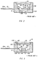
- FIG. 2 shows in simplified schematic form a cross-section through a semiconductor solid state pressure sensor employing a preformed metallic diaphragm, according to other prior art;
- FIG. 3 shows a cross section in simplified schematic form the prior art pressure sensor of US Patent 4,686,764 employing a preformed fluorosilicone diaphragm; and
- FIG. 4 shows in simplified form a cross-section of portions of a solid-state pressure sensor according to the present invention.
- For purposes of explanation, the sensor assemblies and structures described herein are illustrated for a semiconductor solid state sensing element and more particularly, solid state sensing elements having a region for sensing a measurand to be measured on a first surface thereof. Certain sensor devices may also require a region for sensing a reference measurand on a second surface, which may be opposite the first surface. However, those of skill in the art will understand that other sensor configurations may equally well be used. The measurands may be selected from the known measurands; the present example being directed to a pressure or force measurand.
- FIG. 1 shows in simplified schematic form a solid state pressure sensor. FIG. 4 shows a cross-section of the sensor of FIG. 1 In FIG. 1 and 4,
pressure sensor 10 comprises header orbody 11 havinginternal cavity 15 in which is mounted semiconductor solidstate sensing element 14, which may be a chip or die. Electrical leads 12 extend from outside ofbody 11 through the wall ofbody 11 intocavity 15. Signal communication by non-electrical, e.g., optical, means may also be provided. Sensingelement 14 is mounted insidecavity 15 ofbody 11 by known means above aperture orhole 13. This mounting means may include, for example, an adhesive. A reference pressure receiving portion ofsensing element 14 is aligned overaperture 13. Areas on sensingelement 14 are electrically connected byconductors 18 to leads 12, typically bywirebonds 16.Body 11 may be conveniently formed of separate parts or from a single unit.Body 11 is conveniently a dielectric material, preferably plastic, for example, polyphenylene (Noryl), or polyphenylene sulfide (e.g., Ryton R-4). Other materials may be used providedleads 12 are insulated from each other and, preferably, frombody 11, and are suitably sealed. - A method which is allegedly an improvement and which has been used in the prior art is illustrated in FIG. 2. FIG. 2 is a cross-section through a solid state pressure sensing element comprising a
body 11 having upper and lower parts 11a and 11b, leads 12 having external portions 12a and internal portions 12b, and a bar shaped semiconductor sensing element 24 which is attached at one end tobody 11 by clamp means 26 and connected to leads 12 viawirebonds 16. Aprefabricated metal diaphragm 23 separatescavity 22 containing sensing element 24 from the external process media having a pressure measurand to be measured.Hole 13 allows a reference pressure to be communicated tocavity 22 when such is desired. Rigid bar orrod 25 provides mechanical coupling between the center of aPrefabricated metal diaphragm 23 and semiconductor sensing element 24. - While the configuration of FIG. 2 protects sensing element 24 from the process media whose pressure is intended to be measured, the arrangement of FIG. 2 is expensive to manufacture because of the small piece parts which must be individually handled and precisely located within
body 11, and it is also comparatively fragile. It is well known, for example, that semiconductor pressure sensing elements may be extremely brittle. In order to have high sensitivity in the arrangement of FIG. 2, cantilever bar shaped element 24 must be directly coupled viarod 25 todiaphragm 23. Over-pressure conditions applied todiaphragm 23 can readily cause catastrophic failure of sensing element 24. A further disadvantage of the structure of FIG. 2 is that the sensitivity and calibration of the sensor depend critically upon the placement ofbar 25 on sensing element 24 anddiaphragm 23. A further problem with the arrangement of FIG. 2 is that the active regions of sensing element 24 are exposed to the reference ambient entering viahole 13. - As shown in FIG. 3, the prior art solid state sensor according to US 4,686,764 comprises
body 11 having leads 12 with external portions 12a and internal portions 12b.Semiconductor sensing element 14 having reference pressure receiving region 14x is mounted by means 14a on surface llc incavity 15 ofbody 11 overhole 13. Wirebonds 16 are used for coupling the active regions ofsensor 14 to leads 12. The upper surface ofsensor element 14 may be covered with conventional die coat (not shown). However, this is not essential and the die coat may be omitted.Body 11 conveniently extends to the open end ofcavity 15 containingsensing element 14. Sensingelement 14 may be sealed to surface 11c by any convenient means 14a well known in the art. Organic adhesives are a suitable sealing means. The reference pressure entering viahole 13 acts only on portion 14x ofsensor 14 and does not entercavity 15. - Once die 14 has been mounted in
cavity 15 ofbody 11, ′764 teaches that the lower portion 15a ofcavity 15 is to be filled withpressure transfer medium 31. An example of a suitable material is given in the reference as Visilox type 191 silastic manufactured by the Visilox Company of Troy, NY. In order to make the transfer medium material opaque to light, approximately 40 percent by volume of titanium dioxide may be mixed into the Visilox 191 material prior to its being introduced intocavity 15, but this is not essential when the preformed diaphragm is opaque. It is stated to be important that upper surface ofmaterial 31 extends at least above lip 11e. - After being placed into portion 15a of
cavity 15, the Visilox 191 material is to be vacuum cured. - It is necessary to cover
pressure transfer medium 31 with a Prefabricated protective membrane 32 (FIG. 3).Membrane 32 must be flexible and substantially impermeable to the process media of interest even after curing. - It is stated to be important that membrane or
diaphragm 32 be applied topressure transfer material 31 in such a way that substantially no air pockets or other voids are trapped withinmedium 31. This is very difficult to accomplish. If significant voids or pockets are present, the sensitivity and linearity of the pressure transducer will be adversely affected. Substantially void-free application ofmembrane 32 may allegedly be accomplished as illustrated in FIG. 3, in which a first portion ofmembrane 32 is placed in contact with a portion of shelf or lip 11e where the transfer medium meets shelf 11e. Prefabricatedmembrane 32 is then rolled across opening 15 away from the starting location to enclose thecavity 15. It is stated that in the process of rolling outdiaphragm 32 it is necessary to push ahead of the unrolling diaphragm a "bow-wave" ofmaterial 31 which allegedly fills in any exposed empty places or voids withincavity portion 15. - The rolling and squeezing motion of
diaphragm 32 is to be continued until all the voids are filled bymaterial 31, with excess material to be removed. In practice, this is difficult to achieve reliably. The reference teaches thatmembrane 32 may be of any convenient flexible impermeable material. Fluorosilicone is cited as an example of a suitable material formembrane 32. - The prior art disadvantages may be overcome by the means and method of the present invention which are illustrated in FIG. 4, which shows a simplified schematic cross-sectional view of a solid state measurand sensor, similar to FIG. 3, but made according to the present invention.
- As shown in FIG. 4,
solid state sensor 10 comprisesbody 11 havingleads 12 with portions external to thebody 11 and other portions extending into thecavity 15 of thebody 11.Semiconductor sensing element 14 having a reference pressure receiving region is mounted by known means on an exposed surface incavity 15 ofbody 11 overhole 13.Wires 18 are used for coupling the active regions ofsensor 14 toleads 12 where they are conventionally bonded. The upper surface ofsensor element 14 may be covered with conventional die coat (not shown). However, this is not essential and the die coat may be omitted.Body 11 conveniently extends to the open end ofcavity 15 containingsensing element 14. Sensingelement 14 may be sealed to the exposed surface by any convenient means known in the art, including organic adhesives. The reference pressure entering viaaperture 13 acts only on a portion ofsensor 14 and does not entercavity 15. - Once die 14 has been mounted in
cavity 15 ofbody 11, then lower portion 15a ofcavity 15 is at least partially filled with apressure transfer medium 31. It is important that during filling of lower portion 15a ofcavity 15 withmaterial 31 that trapped gas pockets or enclosed voids be avoided as much as possible. This is conveniently accomplished by using a material forpressure transfer medium 31 which has a low viscosity at the time of introduction. It need not fully cure. A measured amount ofmaterial 31 is deposited on and/or around die 14 within the header orbody 11cavity 15 to flow into and fill lower portion 15a ofcavity 15. It is important that upper surface ofmaterial 31 extend at least above thedie 14. -
Medium 31 may be of any convenient material which does not contaminatesensor element 14, which remains in a liquid or at least gel-like or elastic form after introduction and curing of subsequent layers. If a material is used which sets up or becomes hard, then the measurand signal which will subsequently be applied todiaphragm 32 will be attenuated or skewed with temperature excursions before reachingsensor element 14 and thefinished device 10 will be insensitive or inaccurate. The gel may be evacuated to reduce voids. - More elastic materials, even liquids, can also be used. If the
material 31 is at least partially cured after being introduced intocavity 15, then the needed elasticities apply after curing. An example of a suitable material is fluorosilicone dielectric gel, such as Dow-Corning part number X3-6679. - These materials are initially in a liquid or semi-liquid state and upon curing set up to the consistency of a very soft rubber-like material or gel.
- It may be desirable that radiant (light) energy should be excluded from reaching the sensor element. If it is desired to test, laser trim, and/or calibrate the sensor element, such procedures should be completed before covering the sensor die. An opaque diaphragm material may be used as a light blocker, or the transfer medium may be opaque. In order to make the transfer medium material opaque to light, a portion of titanium dioxide or equivalent may be mixed into the pressure transfer material prior to its being introduced into
cavity 15, but this is not essential when the diaphragm is opaque. After being placed into portion 15a ofcavity 15, thematerial 31 may be cured following the manufacturer's recommendations. Those of skill in the art will know the appropriate materials curing cycles. - Some materials may shrink slightly on curing. Another method is to provide an initial fill of
material 31 approximately to the level of cure the initial fill, as described above, and then prior to pouringmembrane 32, a small amount of the material 31 or other liquid is added to bring the level back up to or slightly above the desired level formaterial 31. - The presence of poured-in-
place membrane 32 has been found to be useful in preventing undesirable external materials from reachingsensor element 14. - According to the present invention, it is desired to cover
pressure transfer medium 31 with pour-in-place membrane 32 such as is shown in FIG. 4. The pressure transfer material provides support for the diaphragm.Pourable membrane 32 must be flexible and substantially impermeable to the process media of interest, even after curing. The substitution of a poured-in-place diaphragm for a prefabricated diaphragm is an important variation from the prior art processes for making sensors. - It is preferred that membrane or
diaphragm 32 be deposited on thetransfer material 31 in such a way that substantially no air pockets or other voids are trapped withinmedium 31. With significant voids or pockets present, the sensitivity and linearity of the pressure transducer will be adversely affected. Substantially void-free application ofmembrane 32 may be conveniently accomplished by the method illustrated in FIG. 4, in which a pourable,viscous membrane 32 material is poured in contact with the transfer medium, filling in any exposed empty places or voids within cavity portion 15a, e.g., such as are illustrated at location 15v in FIG. 4. Evacuating may be used to ensure voids are eliminated. Different viscosity materials may eliminate void reducing steps. Note that it may be desirable for formed-in-place membrane 32 to extend above the face surface of the header in some applications, may be level in others, or may be insufficient to extend beyond the header surface in others. These variations are difficult or impossible with the prior art methods. - Materials such as Dow-Corning X3-6679 alone, while having desirable properties as a pressure transfer medium, are sufficiently permeable to many process media so as to provide insufficient protection. Incomplete curing may leave a portion of the material in a liquid state. The
membrane 32 solves these problems.Membrane 32 may be of any suitable and convenient flexible impermeable material which is conveniently pourable. Fluorosilicone is an example of a suitable material formembrane 32. Medical grade RTV type materials permit contact with bodily fluids in medical applications. It is important thatmembrane 32 be flexible after curing since if it is stiff, the pressure signal will be attenuated prior to reachingsensor element 14. Curing should be complete and not continue after manufacture and installation. Thicknesses formembrane 32 in the range 0.001 to 0.10 (25»m to 2.5mm) may be useful, 0.01 to 0.10 inches (0.25-2.5mm) are more useful, with 0.02 to 0.05 inches (0.5-1.2mm) being preferred. - Pressure sensors according to the present invention were constructed wherein
body 11 was circular and in which the initial aperture forcavity 15 had a minor diameter of approximately 0.22 inches (5.6mm), and the chip or die 14 had a mounting area diameter of approximately 0.15 inches (3.8mm). A fluorosilicone diaphragm having an outer diameter corresponding approximately to the size of the body face opening (i.e., the cavity major diameter) was poured in place overpressure transfer medium 31 as described above. In one case the major diameter was about 0.48 inches (12mm). It was determined that the sensitivity of the resulting unit was substantially the same with and withoutmembrane 32. There was no hysteresis. The fluorosilicone used was X3-6679 type material manufactured by Down-Corning of Midland, Michigan. This fluorosilicone material is particularly soft and flexible. If a harder or denser membrane material is desired to be used, then the thickness of the membrane should be correspondingly reduced in order to maintain about the same sensitivity. It is desirable that the thickness of different membrane materials be adjusted approximately inversely proportional to their relative hardness; this being dependent on the intended application and being within the skill of one of ordinary skill within the art. - It will be appreciated by those of ordinary skill in the art, that different membrane materials which are particularly impermeable to certain ambients may be used to cover sensors intended for such ambients.
- It will also be appreciated by those of skill in the art, that the above-described structure and method of fabrication provide a particularly conveniently manufactured membrane protected pressure sensor. No complex mechanical linkages, as were used for example in the structure of FIG. 2 are required. No complicated, difficult "rolling-in-place" diaphragm positioning and/or attaching procedures are required. The finished device as illustrated in FIG. 4 is particularly rugged, is flat, and uses a minimum number of piece parts. Further, no complex physical assembly steps are required for coupling the membrane to the sensing element. The product according to the present invention lends itself to automated assembly and manufacture. Additionally, the device is not readily damaged by over-pressure conditions since the active portion of the solid state sensor element is uniformly supported by attachment
means surrounding hole 13. - The pressure transfer medium (gel) and the poured-in-place diaphragm are of dissimilar materials, preferably both chemically inert and/or mutually incompatible. For example, use of a dimethyl silicone gel is preferred with a fluorosilicone diaphragm, and a fluorosilicone gel is preferred with a dimethyl silicone diaphragm material. Dimethyl silicone gels in combination with dimethyl silicone diaphragms (and fluorosilicone/fluorosilicone) should be avoided, absent some means to prevent chemical interaction between the gel and diaphragm. Skilled artisans in this field will recognize that each diaphragm material has beneficial uses.
- Those of skill in the art will understand that a variety of different sensing elements may be used in connection with the means and methods of the present invention, and further that a wide variety of pressure transfer materials may be employed provided they are sufficiently liquid to be applied substantially void-free in filling cavity portion 15a, and sufficiently elastic after introduction (and curing) to transmit the pressure applied to
membrane 32 tosensor 14 without significant attenuation or hysteresis. Those of skill in the art will also understand that a variety of membrane materials may be used provided they are substantially impermeable to the ambient or process media whose pressures are intended to be measured and sufficiently flexible to be applied by the methods described herein and to avoid attenuation of the pressure signal. Accordingly, the appended claims are intended to include all such reasonable variations in materials.
wherein the pressure transfer medium and the diaphragm material are both unbonded and chemically incompatible, and said pressure transfer medium and said diaphragm material are capable of transferring said pressure to be measured to said sensor element.
Claims (26)
- A method of forming a pressure sensor environmentally protected by a diaphragm, comprising: providing a body (11) having in a first face thereof a cavity (15), wherein said cavity has a first interior surface for receiving a pressure sensor element (14) and a second generally upward facing surface for supporting the diaphragm (32); mounting said pressure sensor element (14) on said first surface; filling at least part of said cavity around said pressure sensor element with a volume of a pressure transfer material (31), said volume being less than the volume of said cavity extending below said body face and excluding the volume of said sensor element; characterised by pouring a volume of a flexible, pourable-in-place diaphragm material above said pressure transfer material sufficient to seal said cavity, wherein said diaphragm material and said pressure transfer material are chemically incompatible.
- The method of Claim 1, characterised in that said diaphragm is formed adjacent to said second surface in the absence of substantial diaphragm material shrinkage.
- The method of Claim 1, characterised in that the pourable-in-place diaphragm material is a flowable polymeric material.
- The method of Claim 2, characterised in that the step of pouring the flexible diaphragm material comprises providing a diaphragm poured from a fluorosilicone material which substantially retains its original volume upon setting.
- The method of Claim 2, characterised in that the step of pouring the flexible diaphragm material comprises providing a diaphragm poured from a dimethyl silicone material which substantially retains its original volume upon setting.
- The method of Claim 2, characterised in that the step of pouring the flexible diaphragm material comprises providing a diaphragm poured from a medical grade silicone 'rubber' material which substantially retains its original volume upon setting.
- The method of Claim 1, characterised in that it further includes the step of testing the pressure sensor element before filling the cavity.
- The method of Claim 7, characterised in that it further includes the steps of adjusting the sensor element and calibrating the pressure element before sealing the cavity.
- The method of Claim 1, characterised in that the cavity dimensions are selected to provide minimal fill volumes.
- The method of Claim 1, characterised in that said second generally upward facing surface bottoms peripherally a first recess of given cross-section, and a second recess from said first recess, of smaller cross-section than said first recess, is substantially bottomed by said first interior surface for supporting said pressure sensor element (14), whereby said first recess and said second recess form said cavity (15) into a stepped cavity in said body face; the method further comprising making electrical connections (18) to said pressure sensor element; said pressure transfer material (31) being a non-gaseous pressure transfer medium substantially filling said second recess; said flexible diaphragm material (32) being poured in contact with said pressure transfer medium and with said second surface and chosen so that it does not shrink upon curing thereof.
- A pressure sensor comprising:(a) a body (11) having in a first face surface thereof a first recess of given cross-section, bottomed peripherally by means for supporting a diaphragm (32) comprising a first upward facing surface, and a second recess displaced from said first recess, said second recess being of smaller cross-section than said first recess and being substantially bottomed by a second upward facing surface for supporting a pressure sensor element (14), wherein said first recess and said second recess form a unitary stepped cavity (15) in said body face surface;(b) signal communicating electrical pathways (18, 12) into said cavity;(c) a pressure sensor element connected to the communicating pathways, the sensor being characterised by:(d) a non-hardening flexible diaphragm (32) poured in place; and(e) means for i) isolating said sensor element from the pressure to be measured, ii) for transferring said pressure to said sensor element, and iii) for supporting said diaphragm, comprising a non-hardening pressure transfer medium (31),wherein the pressure transfer medium and the diaphragm material are both unbonded and chemically incompatible, and said pressure transfer medium and said diaphragm material are capable of transferring said pressure to be measured to said sensor element.
- The sensor of Claim 11, characterised in that the pressure transfer medium is a dimethyl silicone based material.
- The sensor of Claim 11, characterised in that the pressure transfer medium is a fluorosilicone material.
- The sensor of Claim 11, characterised in that the diaphragm material is fluorosilicone based material.
- The sensor of Claim 11, characterised in that the diaphragm material is dimethyl silicone based material.
- The sensor of Claim 12, characterised in that it further includes an opaquing agent to isolate the sensor element from light.
- The sensor of Claim 11, characterised in that it further includes means for transferring a second measurand to the sensing element.
- The sensor of Claim 11, characterised in that the sensing element comprises a solid state sensor element.
- The sensor of Claim 11, characterised in that said first recess is of a greater cross-section than said second recess.
- The sensor of Claim 11, characterised in that said first recess is of a lesser volume that said second recess.
- The sensor of Claim 11, characterised in that the volume of said first recess substantially includes the diaphragm material.
- The sensor of Claim 11, characterised in that said first recess includes a partial bottom surface in support of said diaphragm material.
- The sensor of Claim 11, characterised in that said diaphragm forms a substantially impermeable barrier having an outward facing surface and an inward facing surface facing and supported by said pressure transfer medium and by said first upward facing surface at its periphery.
- The sensor of Claim 11, characterised in that said outward facing surface is recessed below the body first upward facing surface.
- The sensor of Claim 17, characterised in that said means for communicating a second measurand to said sensing element includes an aperture in said second upward facing surface and a communicating passageway into said second recess.
- The sensor of Claim 11, characterised in that said diaphragm material forms a substantially impermeable barrier having an outward facing surface and an inward facing surface facing and supported by said pressure transfer material at its centre and by said upward facing surface at its periphery, the outward facing surface being substantially level with the body first face.
Applications Claiming Priority (3)
| Application Number | Priority Date | Filing Date | Title |
|---|---|---|---|
| US16359888A | 1988-03-03 | 1988-03-03 | |
| US163598 | 1988-03-03 | ||
| PCT/US1989/000823 WO1989008244A1 (en) | 1988-03-03 | 1989-03-03 | Protected pressure sensor |
Publications (3)
| Publication Number | Publication Date |
|---|---|
| EP0400074A1 EP0400074A1 (en) | 1990-12-05 |
| EP0400074A4 EP0400074A4 (en) | 1992-02-05 |
| EP0400074B1 true EP0400074B1 (en) | 1994-09-28 |
Family
ID=22590730
Family Applications (1)
| Application Number | Title | Priority Date | Filing Date |
|---|---|---|---|
| EP89903349A Expired - Lifetime EP0400074B1 (en) | 1988-03-03 | 1989-03-03 | Protected pressure sensor |
Country Status (6)
| Country | Link |
|---|---|
| EP (1) | EP0400074B1 (en) |
| JP (1) | JPH02503828A (en) |
| AT (1) | ATE112389T1 (en) |
| CA (1) | CA1324892C (en) |
| DE (1) | DE68918584T2 (en) |
| WO (1) | WO1989008244A1 (en) |
Cited By (2)
| Publication number | Priority date | Publication date | Assignee | Title |
|---|---|---|---|---|
| DE19840829B4 (en) * | 1998-09-07 | 2005-10-20 | Siemens Ag | Method for attaching a micromechanical sensor in a housing and sensor arrangement |
| EP4502563A1 (en) * | 2023-08-01 | 2025-02-05 | Honeywell International Inc. | A fluid coupling medium for use in a media-isolated pressure sensor |
Families Citing this family (7)
| Publication number | Priority date | Publication date | Assignee | Title |
|---|---|---|---|---|
| DE4023420A1 (en) * | 1990-07-24 | 1992-01-30 | Pfister Gmbh | PRESSURE SENSOR |
| US6453749B1 (en) | 1999-10-28 | 2002-09-24 | Motorola, Inc. | Physical sensor component |
| US6769319B2 (en) | 2001-07-09 | 2004-08-03 | Freescale Semiconductor, Inc. | Component having a filter |
| US8162839B2 (en) | 2003-08-27 | 2012-04-24 | Microtech Medical Technologies Ltd. | Protected passive resonating sensors |
| US20050124896A1 (en) * | 2003-08-25 | 2005-06-09 | Jacob Richter | Method for protecting implantable sensors and protected implantable sensors |
| DE102004012059A1 (en) * | 2004-03-11 | 2005-10-06 | Siemens Ag | Process for production of a body including a housing part, adjuvant material and heat protection matrix useful useful in the production of sensor devices |
| JP5710310B2 (en) * | 2011-02-18 | 2015-04-30 | アルプス電気株式会社 | Pressure measuring device using load sensor |
Family Cites Families (8)
| Publication number | Priority date | Publication date | Assignee | Title |
|---|---|---|---|---|
| GB2096825A (en) * | 1981-04-09 | 1982-10-20 | Sibbald Alastair | Chemical sensitive semiconductor field effect transducer |
| JP2504737B2 (en) * | 1985-07-19 | 1996-06-05 | シチズン時計株式会社 | Pressure sensor unit |
| US4655088A (en) * | 1985-10-07 | 1987-04-07 | Motorola, Inc. | Unibody pressure transducer package |
| US4686764A (en) * | 1986-04-22 | 1987-08-18 | Motorola, Inc. | Membrane protected pressure sensor |
| US4732042A (en) * | 1986-04-22 | 1988-03-22 | Motorola Inc. | Cast membrane protected pressure sensor |
| US4691573A (en) * | 1986-06-16 | 1987-09-08 | Fisher Controls International, Inc. | Pressure sensor |
| USH606H (en) * | 1987-11-27 | 1989-03-07 | Motorola, Inc. | Pressure sensor assembly |
| JPH05225680A (en) * | 1992-02-10 | 1993-09-03 | Matsushita Electric Ind Co Ltd | Magnetic disk unit |
-
1989
- 1989-03-03 CA CA000592743A patent/CA1324892C/en not_active Expired - Fee Related
- 1989-03-03 EP EP89903349A patent/EP0400074B1/en not_active Expired - Lifetime
- 1989-03-03 AT AT89903349T patent/ATE112389T1/en not_active IP Right Cessation
- 1989-03-03 JP JP1503149A patent/JPH02503828A/en active Pending
- 1989-03-03 WO PCT/US1989/000823 patent/WO1989008244A1/en not_active Ceased
- 1989-03-03 DE DE68918584T patent/DE68918584T2/en not_active Expired - Fee Related
Non-Patent Citations (1)
| Title |
|---|
| US H H 606 * |
Cited By (2)
| Publication number | Priority date | Publication date | Assignee | Title |
|---|---|---|---|---|
| DE19840829B4 (en) * | 1998-09-07 | 2005-10-20 | Siemens Ag | Method for attaching a micromechanical sensor in a housing and sensor arrangement |
| EP4502563A1 (en) * | 2023-08-01 | 2025-02-05 | Honeywell International Inc. | A fluid coupling medium for use in a media-isolated pressure sensor |
Also Published As
| Publication number | Publication date |
|---|---|
| DE68918584T2 (en) | 1995-01-26 |
| CA1324892C (en) | 1993-12-07 |
| EP0400074A4 (en) | 1992-02-05 |
| DE68918584D1 (en) | 1994-11-03 |
| ATE112389T1 (en) | 1994-10-15 |
| JPH02503828A (en) | 1990-11-08 |
| EP0400074A1 (en) | 1990-12-05 |
| WO1989008244A1 (en) | 1989-09-08 |
Similar Documents
| Publication | Publication Date | Title |
|---|---|---|
| US4993265A (en) | Protected pressure sensor and method of making | |
| US4686764A (en) | Membrane protected pressure sensor | |
| US4732042A (en) | Cast membrane protected pressure sensor | |
| US4842685A (en) | Method for forming a cast membrane protected pressure sensor | |
| JP4726481B2 (en) | Barometric pressure sensor | |
| US4656454A (en) | Piezoresistive pressure transducer with elastomeric seals | |
| EP0767899B1 (en) | Method of mounting an absolute pressure sensor | |
| EP2505981B1 (en) | An absolute capacitive micro pressure sensor | |
| US6401545B1 (en) | Micro electro-mechanical system sensor with selective encapsulation and method therefor | |
| US5438876A (en) | Modular diaphragm pressure sensor with peripheral mounted electrical terminals | |
| US6351996B1 (en) | Hermetic packaging for semiconductor pressure sensors | |
| US6255728B1 (en) | Rigid encapsulation package for semiconductor devices | |
| JP4550364B2 (en) | Semiconductor pressure sensor | |
| US8631708B2 (en) | Apparatus and method for minimizing drift of a piezo-resistive pressure sensor due to the progressive release of mechanical stress over time | |
| EP0545319B1 (en) | Semiconductor pressure sensor having double diaphragm structure | |
| US5029478A (en) | Fluid isolated self-compensating absolute pressure sensor transducer | |
| WO1999032865A2 (en) | Media compatible packages for pressure sensing devices | |
| JPH1068666A (en) | Differential pressure detector and method for manufacturing the same | |
| US5741975A (en) | Media isolated differential pressure sensor and fluid injection method | |
| CA1324892C (en) | Protected pressure sensor | |
| EP1601942B1 (en) | Silicon pressure sensor with decreased pressure equalization between measured pressure and reference chamber | |
| US6591686B1 (en) | Oil filled pressure transducer | |
| JP3892065B2 (en) | Sensor device and sensor chip fixing method | |
| CN215492215U (en) | Medium isolation type pressure sensor | |
| JPH05133827A (en) | Semiconductor pressure sensor |
Legal Events
| Date | Code | Title | Description |
|---|---|---|---|
| PUAI | Public reference made under article 153(3) epc to a published international application that has entered the european phase |
Free format text: ORIGINAL CODE: 0009012 |
|
| 17P | Request for examination filed |
Effective date: 19900220 |
|
| AK | Designated contracting states |
Kind code of ref document: A1 Designated state(s): AT BE CH DE FR GB IT LI LU NL SE |
|
| A4 | Supplementary search report drawn up and despatched |
Effective date: 19911213 |
|
| AK | Designated contracting states |
Kind code of ref document: A4 Designated state(s): AT BE CH DE FR GB IT LI LU NL SE |
|
| 17Q | First examination report despatched |
Effective date: 19930122 |
|
| GRAA | (expected) grant |
Free format text: ORIGINAL CODE: 0009210 |
|
| AK | Designated contracting states |
Kind code of ref document: B1 Designated state(s): AT BE CH DE FR GB IT LI LU NL SE |
|
| PG25 | Lapsed in a contracting state [announced via postgrant information from national office to epo] |
Ref country code: IT Free format text: LAPSE BECAUSE OF FAILURE TO SUBMIT A TRANSLATION OF THE DESCRIPTION OR TO PAY THE FEE WITHIN THE PRESCRIBED TIME-LIMIT;WARNING: LAPSES OF ITALIAN PATENTS WITH EFFECTIVE DATE BEFORE 2007 MAY HAVE OCCURRED AT ANY TIME BEFORE 2007. THE CORRECT EFFECTIVE DATE MAY BE DIFFERENT FROM THE ONE RECORDED. Effective date: 19940928 Ref country code: NL Effective date: 19940928 Ref country code: BE Effective date: 19940928 Ref country code: CH Effective date: 19940928 Ref country code: LI Effective date: 19940928 Ref country code: AT Effective date: 19940928 |
|
| REF | Corresponds to: |
Ref document number: 112389 Country of ref document: AT Date of ref document: 19941015 Kind code of ref document: T |
|
| REF | Corresponds to: |
Ref document number: 68918584 Country of ref document: DE Date of ref document: 19941103 |
|
| ET | Fr: translation filed | ||
| PG25 | Lapsed in a contracting state [announced via postgrant information from national office to epo] |
Ref country code: SE Effective date: 19941228 |
|
| REG | Reference to a national code |
Ref country code: CH Ref legal event code: PL |
|
| NLV1 | Nl: lapsed or annulled due to failure to fulfill the requirements of art. 29p and 29m of the patents act | ||
| PG25 | Lapsed in a contracting state [announced via postgrant information from national office to epo] |
Ref country code: LU Free format text: LAPSE BECAUSE OF NON-PAYMENT OF DUE FEES Effective date: 19950331 |
|
| PLBE | No opposition filed within time limit |
Free format text: ORIGINAL CODE: 0009261 |
|
| STAA | Information on the status of an ep patent application or granted ep patent |
Free format text: STATUS: NO OPPOSITION FILED WITHIN TIME LIMIT |
|
| 26N | No opposition filed | ||
| REG | Reference to a national code |
Ref country code: GB Ref legal event code: IF02 |
|
| PGFP | Annual fee paid to national office [announced via postgrant information from national office to epo] |
Ref country code: GB Payment date: 20030204 Year of fee payment: 15 |
|
| PGFP | Annual fee paid to national office [announced via postgrant information from national office to epo] |
Ref country code: FR Payment date: 20030303 Year of fee payment: 15 |
|
| PGFP | Annual fee paid to national office [announced via postgrant information from national office to epo] |
Ref country code: DE Payment date: 20030331 Year of fee payment: 15 |
|
| PG25 | Lapsed in a contracting state [announced via postgrant information from national office to epo] |
Ref country code: GB Free format text: LAPSE BECAUSE OF NON-PAYMENT OF DUE FEES Effective date: 20040303 |
|
| PG25 | Lapsed in a contracting state [announced via postgrant information from national office to epo] |
Ref country code: DE Free format text: LAPSE BECAUSE OF NON-PAYMENT OF DUE FEES Effective date: 20041001 |
|
| GBPC | Gb: european patent ceased through non-payment of renewal fee | ||
| PG25 | Lapsed in a contracting state [announced via postgrant information from national office to epo] |
Ref country code: FR Free format text: LAPSE BECAUSE OF NON-PAYMENT OF DUE FEES Effective date: 20041130 |
|
| REG | Reference to a national code |
Ref country code: FR Ref legal event code: ST |