EP0399794A2 - Gerät für Tonertransport, Wärmefixierung und Bilderzeugung - Google Patents
Gerät für Tonertransport, Wärmefixierung und Bilderzeugung Download PDFInfo
- Publication number
- EP0399794A2 EP0399794A2 EP90305571A EP90305571A EP0399794A2 EP 0399794 A2 EP0399794 A2 EP 0399794A2 EP 90305571 A EP90305571 A EP 90305571A EP 90305571 A EP90305571 A EP 90305571A EP 0399794 A2 EP0399794 A2 EP 0399794A2
- Authority
- EP
- European Patent Office
- Prior art keywords
- belt
- toner
- image
- location
- layer
- Prior art date
- Legal status (The legal status is an assumption and is not a legal conclusion. Google has not performed a legal analysis and makes no representation as to the accuracy of the status listed.)
- Granted
Links
Images


Classifications
-
- G—PHYSICS
- G03—PHOTOGRAPHY; CINEMATOGRAPHY; ANALOGOUS TECHNIQUES USING WAVES OTHER THAN OPTICAL WAVES; ELECTROGRAPHY; HOLOGRAPHY
- G03G—ELECTROGRAPHY; ELECTROPHOTOGRAPHY; MAGNETOGRAPHY
- G03G15/00—Apparatus for electrographic processes using a charge pattern
- G03G15/14—Apparatus for electrographic processes using a charge pattern for transferring a pattern to a second base
- G03G15/16—Apparatus for electrographic processes using a charge pattern for transferring a pattern to a second base of a toner pattern, e.g. a powder pattern, e.g. magnetic transfer
- G03G15/169—Apparatus for electrographic processes using a charge pattern for transferring a pattern to a second base of a toner pattern, e.g. a powder pattern, e.g. magnetic transfer with means for preconditioning the toner image before the transfer
-
- G—PHYSICS
- G03—PHOTOGRAPHY; CINEMATOGRAPHY; ANALOGOUS TECHNIQUES USING WAVES OTHER THAN OPTICAL WAVES; ELECTROGRAPHY; HOLOGRAPHY
- G03G—ELECTROGRAPHY; ELECTROPHOTOGRAPHY; MAGNETOGRAPHY
- G03G15/00—Apparatus for electrographic processes using a charge pattern
- G03G15/14—Apparatus for electrographic processes using a charge pattern for transferring a pattern to a second base
- G03G15/16—Apparatus for electrographic processes using a charge pattern for transferring a pattern to a second base of a toner pattern, e.g. a powder pattern, e.g. magnetic transfer
- G03G15/1665—Apparatus for electrographic processes using a charge pattern for transferring a pattern to a second base of a toner pattern, e.g. a powder pattern, e.g. magnetic transfer by introducing the second base in the nip formed by the recording member and at least one transfer member, e.g. in combination with bias or heat
- G03G15/167—Apparatus for electrographic processes using a charge pattern for transferring a pattern to a second base of a toner pattern, e.g. a powder pattern, e.g. magnetic transfer by introducing the second base in the nip formed by the recording member and at least one transfer member, e.g. in combination with bias or heat at least one of the recording member or the transfer member being rotatable during the transfer
-
- G—PHYSICS
- G03—PHOTOGRAPHY; CINEMATOGRAPHY; ANALOGOUS TECHNIQUES USING WAVES OTHER THAN OPTICAL WAVES; ELECTROGRAPHY; HOLOGRAPHY
- G03G—ELECTROGRAPHY; ELECTROPHOTOGRAPHY; MAGNETOGRAPHY
- G03G15/00—Apparatus for electrographic processes using a charge pattern
- G03G15/22—Apparatus for electrographic processes using a charge pattern involving the combination of more than one step according to groups G03G13/02 - G03G13/20
- G03G15/23—Apparatus for electrographic processes using a charge pattern involving the combination of more than one step according to groups G03G13/02 - G03G13/20 specially adapted for copying both sides of an original or for copying on both sides of a recording or image-receiving material
- G03G15/231—Arrangements for copying on both sides of a recording or image-receiving material
- G03G15/238—Arrangements for copying on both sides of a recording or image-receiving material using more than one reusable electrographic recording member, e.g. single pass duplex copiers
-
- G—PHYSICS
- G03—PHOTOGRAPHY; CINEMATOGRAPHY; ANALOGOUS TECHNIQUES USING WAVES OTHER THAN OPTICAL WAVES; ELECTROGRAPHY; HOLOGRAPHY
- G03G—ELECTROGRAPHY; ELECTROPHOTOGRAPHY; MAGNETOGRAPHY
- G03G15/00—Apparatus for electrographic processes using a charge pattern
- G03G15/22—Apparatus for electrographic processes using a charge pattern involving the combination of more than one step according to groups G03G13/02 - G03G13/20
- G03G15/24—Apparatus for electrographic processes using a charge pattern involving the combination of more than one step according to groups G03G13/02 - G03G13/20 whereby at least two steps are performed simultaneously
-
- G—PHYSICS
- G03—PHOTOGRAPHY; CINEMATOGRAPHY; ANALOGOUS TECHNIQUES USING WAVES OTHER THAN OPTICAL WAVES; ELECTROGRAPHY; HOLOGRAPHY
- G03G—ELECTROGRAPHY; ELECTROPHOTOGRAPHY; MAGNETOGRAPHY
- G03G2215/00—Apparatus for electrophotographic processes
- G03G2215/16—Transferring device, details
- G03G2215/1676—Simultaneous toner image transfer and fixing
- G03G2215/168—Simultaneous toner image transfer and fixing at the first transfer point
- G03G2215/1685—Simultaneous toner image transfer and fixing at the first transfer point using heat
Definitions
- the present invention relates to improvements in mass transport systems, and to such systems wherein a discrete quantity of material is moved from a first location maintained at a first temperature, to a second location maintained at a different temperature. It relates in particular to systems such as a printing system wherein an image- or color-forming material of slight mass is carried to a second location of higher temperature where it is fused to a receiving medium.
- the primary function of the belt is to provide a transport mechanism to carry the developed toner image to a high temperature fusing and transfer station.
- the belt is a relatively thick belt, e.g., one or more millimeters thick, that is operated isothermally at a temperature over 100° Celsius which is sufficient to fuse the transported toner.
- the belt serves to isolate the primary latent-image forming member, which is a photoconductive belt, from the high fusing temperatures; this allows the photoconductive belt to operate with a conventional powdered toner image development technology.
- Such construction results in a complex assembly wherein a first image forming and toner transport mechanism is operated at one temperature, and a comparably large transport assembly is maintained at a higher temperature within the machine.
- the machine requires a significant power input for both its heated and cooled portions, and is mechanically complex.
- the transfer of toner between two or more intermediate members adds considerations of image quality.
- a printing system wherein a transport member, illustratively an endless belt, moves between an unheated location where it picks up particles, and a heated location where the particles are melted and transferred to a sheet to form a print.
- the belt has a low thermal mass and portions of the belt moving in opposite directions between the heated and unheated locations are maintained in proximity so that they exchange heat. This reduces the energy required to bring each portion of the belt about each location into thermal equilibrium with that location, reducing the amount of energy lost due to thermal cycling of the belt.
- the transport member has a multi-layer structure with a sublayer and a surface layer.
- the sublayer is an elastomeric layer of a softness which yields at low pressure to effectively conform at a dimension characteristic of a print surface of a fibrous roughness, and the surface or outer layer which is formed of a material which is hard at spatial frequencies below that characteristic dimension.
- a charge deposition print head structure deposits a charge distribution on the belt member to form an electrostatic latent image.
- a dielectric filler material may be added to the material of at least one layer to achieve a belt capacitance of 50-250 pf/cm2, and the outer coating layer enables a single imaging member to achieve both toner pick up and release for image formation and printing.
- FIGURE 1 illustrates in schema a principal aspect of the present invention, wherein an apparatus 1 moves a discrete mass of material between a first location 10 maintained at a first temperature, and a second location 20 maintained at a different temperature, through an intermediate region 30.
- location 10 is a "cold" location, with its temperature range maintained in a preset operating range by a cooler or ventilator 12, and location 20 is a "hot” location, maintained at a higher temperature by a heater 22.
- Cooler 12 and heater 22 may be omitted in applications where process conditions at the respective locations, such as a continuous influx of cool or hot material, provide the appropriate heat level. Further, the relative positions of the hot and cold locations may be interchanged, so long as there are two process locations maintained at differing temperatures.
- the material is received by a material receiving unit 18 at the other location, having undergone a temperature change corresponding to the difference between the depositing and receiving environments.
- a thermal shunt is provided between counter-moving hot and cold portions of the belt to diminish the amount of heat transported from the hot region of the apparatus. This is achieved by having oppositely moving portions of the belt 5a, 5b maintained in close proximity, and preferably contacting each other, in a region 30 between locations 10 and 20, so that they exchange heat.
- a pair of path-defining idler rollers or shoes 6a, 7a maintain the desired belt path.
- the cold-to-hot moving belt portion 5b which carries deposited material, receives heat from the hot-to-cold moving belt portion 5a. This counterflow heat exchange raises the temperature of portion 5b and the material it carries, while lowering the temperature of the empty return portion 5a.
- the heat capacity, thermal conductivity, belt thickness and belt speed are selected to allow effective heat transfer between the counter-moving belt portions, so that only a small amount of heat is transported to location 10. This construction reduces the amount of energy lost by unwanted energy transport between the two locations, and reduces the amount of energy required to maintain the operating temperature of each of the locations.
- FIGURE 2 shows a printing or coating apparatus 100 employing the counterflow heat exchange transport system of FIGURE 1. Corresponding elements are numbered identically, and are laid out in the same relative positions for clarity of exposition.
- the apparatus functions to deliver a heat fusible thermoplastic, e.g., a pigment or toner, to a heated station where it is transferred to a moving web or sheet 150.
- a heat fusible thermoplastic e.g., a pigment or toner
- the belt 5 is a belt having a dielectric layer which is charged to form a latent charge image, and toner particles from a reservoir 8 are applied by a brush or other applicator 108 so that they adhere to the charged portions of the belt.
- the belt outer surface has a low surface free energy, so that the toner powder adheres only in the charged regions of the latent image.
- the adhered toner is transported to the heated station at roller 7 where an array of heaters within the roller as well as heater lamps 122 directed at the belt soften the transported toner.
- a paper web 150 is fed by a feed mechanism (not shown) and is preferably preheated (e.g., by the same heater 122 at shoulder 122a) before it is pressed at a relatively low pressure against the belt 5 by a print roller 125 to receive the softened toner therefrom.
- This "transfuse" step contrasts with conventional processes, wherein the transferred image is generally fused to the paper at a separate heating station.
- a scraper 126 maintains the roller 125 clean, and a cleaner roller 128 having an absorbent or adhesive jacket contacts the belt to pick up any untransferred residual toner from the belt, so that the portion of the belt 5a leaving the heated roller 7 is clean.
- knee rollers 7a, 6a preferably position the intermediate belt portions 5a, 5b in heat-exchange contact.
- a platen 131 (shown in phantom) of non heat conductive material and low thermal mass may urge the counter-moving belt portions into more intimate contact between the knee rollers.
- an intermediate plate of conductive low friction material, such as cast iron may be placed between the two moving belt portions to conduct heat from one to the other in a thermal shunt.
- the cleaned and cooled belt portion 5a passes to an electrostatic imaging area 140 where a corona discharger, e.g., a corona rod 141, erases the residual belt surface charge distribution.
- the belt then passes to one or more controllable print heads 142, 144 which selectively deposit an imagewise charge distribution on the moving belt so that toner next applied by applicator 10B will adhere to the belt with a spatial distribution corresponding to the desired image.
- the printhead 144 was an ionographic printhead of the general type shown in U.S. Patent 4,160,257 and later patents. Printhead 144 may, however, comprise an electrostic pin array or other latent-image charge applying means.
- the two latent image depositing printheads 142, 144 illustrate two different approaches to mounting a printhead in relation to the belt.
- Printhead 144 is opposed to the drum 6, creating an image deposition geometry similar to that of existing dielectric drum-based systems presently on the market.
- Printhead 142 is positioned opposite an anvil 142a against which the belt is urged.
- Anvil 142a is shaped to provide a desired surface flatness or curvature in order for the belt to faithfully receive the charge pattern formed by printhead 142.
- This latter construction reveals that the described dielectric belt system is adapted to generate latent charge images by the placement of plural electrostatic or ionographic printheads at arbitrary positions along the belt ahead of the toner applicator 8, 108.
- a single printhead e.g., printhead 144, is sufficient for single-tone or single-color printing.
- the toner employed in the prototype was a magnetic dry powder toner with a meltable thermoplastic pigment material. Good results were obtained with the common Hitachi HI-TONER HMT201 heat fusing magnetic toner operating with a hot drum maintained at 165° Celsius and a belt speed of 38 cm/sec. This particular toner is compounded with a 10-30 micron particle size distribution. Similar single or multi-component fusible toners, such as a Coates M7094, yield comparable results with drum temperatures in the range of 105° to 145°C at this speed.
- the system of Figure 2 has several advantageous properties.
- the transferred toner is carried on the sheet to a separate fusing station, there is negligible airborn toner dust released into the electrostatic image-generating region.
- the heat-softened toner is transferred to the web 150 using a relatively low contact pressure, under approximately 6.89 x 10⁵Pa (100 psi), so that high pressure skew rollers, which could smear the image, are not necessary.
- the low pressure resilient rollers can transfer the image to relatively thick, rough or electrically conductive substrates, thus providing a new process for forming patterns or images on such materials.
- the heat-softened toner produces archival quality adhesion to the print. It is also observed that by using a single imaging element consisting of a belt, image registration between different stations is easily achieved. Furthermore, changes of printing speed may be effected without substantial modification of the mechanical transport mechanisms.
- a belt suitable for the system 100 has two sets of characteristics.
- the heat capacity and heat-transfer characteristics are preferably such that effective counterflow heat exchange occurs at reasonable belt operating speeds.
- the belt charging and toner pick-up and release properties are preferably such that a suitable latent charge image is formed, and that the belt effectively picks up and then fully releases the toner in each image cycle.
- KAPTON is a Trade Mark
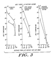
- Figure 3 shows representative temperature readings taken on belts of the above materials having a length of approximately one meter and run on a test jig at a speed of approximately 0.5 m/sec. The temperature was measured at points A, B, C, D, E corresponding to those shown in Figure 2, after an initial warm up period. As shown, the total heat transfer between portions of the belt, which is proportional to the difference T E - T D , and the power lost to the cold drum, which is proportional to the temperature difference TB - TC, are each significantly better with the uncoated Kapton belt. The stainless steel belt, because of its greater heat capacity, did not effectively reduce the excess hot side belt temperature. similarly, the PTFE-coated belt was less effective at this belt speed due to its increased mass.
- the belt speed of approximately 0.5 m/sec. is representative of a desirable speed for a printer to achieve a printing speed of one sheet or more per second.
- the ability of the countermoving belt portions to exchange heat and each reach a substantially uniform temperature through their thickness dimension depends on their thickness, specific heat, length of contact, belt speed and frictional forces. Applicant has found that a belt thickness of approximately .10 mm, and preferably in the range of .02 - 0.20 mm, provides effective transfer for the full thickness of the belt at a range of belt speeds of 0.1 to 2.5 m/sec. suitable for printing.
- a number of commercially available film or sheet materials such as stainless steel, beryllium-copper, various forms of Kapton sheet, and other materials are all suitable belt materials, possessing the necessary tensile strength, heat mass and conductivity. At higher speeds optimal for printing, materials with a lesser heat mass are superior. Higher thermal conductivity does not markedly affect the heat transfer over the range of small belt thicknesses contemplated.
- the facing layers of the belt are formed of a dielectric material, so that they accumulate charge, then a measurable improvement in heat transfer characteristics occurs due to the opposing belt portions being drawn into more effective thermal contact by electrostatic attraction between the oppositely moving portions of the charged belt.
- An assymmetry in the locations of roller placement or the like is sufficient to cause the necessary difference in triboelectric charging of the two counter-moving belt portions which establishes such attraction.
- the belt is somewhat conductive to prevent excessive static charge build up that increases the mechanical drag of the belt.
- the second aspect of belt construction which is important to the operation of the thermoplastic printing apparatus 100 relates to the toner pick-up and release characteristics of the belt. These attributes will be discussed with reference to the above-described printhead structure, which, in accordance with general principles known in the literature, operates by depositing a latent image charge on a dielectric member such that a charge up to several hundred volts is deposited at a point of the member for attracting toner particles to the dielectric member.
- a belt with a capacitance of approximately 125 to 225 pf/cm2 For such operation, applicant has employed a belt with a capacitance of approximately 125 to 225 pf/cm2, and considers a preferred range for other common charging and toning systems to be 50 to 500 pf/cm2.
- a belt capacitance of approximately 1000 pf/cm2 may be desired, and for other systems operation with a belt capacitance as low as 10 pf/cm2 may be feasible.
- the construction of a preferred belt having a capacitance of 125-225 pf/cm2 falling within such capacitance range is discussed in greater detail below, following consideration of toner release characteristics.
- the outer skin of the belt is preferably of a low surface free energy material, in order to assure that powdered toner is attracted to and maintained at only those regions bearing a latent image charge.
- the low surface free energy material is abhesive. Because of this abhesive property, the toner tends to cluster into droplets when softened, and this effect may degrade the quality of the transferred image.
- microscopic voids appear in the transferred image and correspond to irregular surface features in the paper or print medium.
- paper fibers, grit and surface features having a dimension of approximately .01 mm characteristic of the surface roughness of a paper surface may prevent the full transfer of toner when the heated toner-bearing belt is pressed against a sheet.
- the hard coating is sufficiently hard to prevent surface conformance to features of 10nm (100 Angstroms) or less, and thus prevents the Van der Wals molecular attractive forces from acting on a toner particle or softened toner cluster over an area of intimate contact sufficient to adhere it to the belt. This assures that the surface is not “tacky” and does not develop sufficient molecular attractive forces to retain toner in the absence of the applied latent image charge, or in the presence of the mechanical adhesion of the heated toner to paper.
- suitable elastomeric and hard coating properties may be obtained with an elastomeric layer approximately .05 mm thick formed on a Kapton belt with a silicone rubber of a 30 Shore A durometer, overcoated with a .005 mm thick layer of a polymer having a hardness of approximately 35-45 Shore D.
- Kapton is a cured sheet material formed from polyimide resin
- Ultem is a polyetherimide
- Nomex is a high temperature-resistant nylon fibre
- Kevlar cloth is a woven fibre material formed from a fluoroelastomer.
- a suitable hard coating material is the silicone resin conformal coating material sold by Dow Corning as its R-4-3117 conformal coating. This is a methoxy-functional silicone resin in which a high degree of cross-linking during curing adds methoxy groups to elevate the overall molecular weight of the polymerized coating.
- Suitable materials for the belt substrate include .05 mm thick films of Ultem,* Kapton* or other relatively strong and inextensible web materials such as silicone-filled woven Nomex*or Kevlar*cloth, capable of operating at temperatures of up to approximately 200°C.
- Suitable conductive material is included in or on the substrate layer to control charging and provide a ground plane.
- Suitable elastomeric intermediate layer materials include silicone rubbers, fluoropolymers such as Viton, and other heat-resistant materials having a hardness of about 20-50 Shore A.
- Figures 4A, 4B, 4C illustrate three different belt constructions illustrating a range of features.
- a belt 50 includes an electrically conductive support 51 of .05 mm thick aluminized Kapton, having a .04 mm thick layer 52 of a silicone rubber overcoated with a hard skin coat 53 which is .005 mm thick.
- Layer 52 has a 35 Shore A durometer
- surface coat 53 has a 45 Shore D durometer.
- the multilayer construction is preferable modified by including a high dielectric filler material in at least one layer. The use of filler in this manner increases the hardness, and accordingly a thicker elastomer layer or a softer elastomer is used in such a construction to retain the desired surface conformability.
- Figure 4B shows such a filled belt construction, 60.
- the substrate is formed of a .05 mm thick thermally conductive film 61 having a metalized face 61a, such as the MT film of Dupont.
- Elastomeric layer 62 is formed of a .05 mm coating of silicone rubber compounded by Castall, Inc. of Weymouth, Massachusetts, loaded with a sufficient amount of barium titanate in a prepared formulation to achieve a dielectric constant of 13, and having a net hardness of about 40-45 Shore A.
- the hard skin outer coat 53 is identical to that of Figure 4A.
- Other additives may be mixed in or substituted in order to adjust the belt capacitance, thermal conductivity or both.
- Figure 4C shows an alternative belt construction 70 wherein a low density woven fabric belt 71 is impregnated with a soft electrically conductive silicone rubber binder 71a to form a conductive .075 mm thick.
- a suitable rubber may have a 35 Shore A durometer, and electrical conductivity of 103 ohm centimeters.
- the substrate is conformable, and the silicone rubber layer 72 may thus be quite thin since no additional softness is needed.
- layer 72 may be formed with an elastomer of 30 Shore A hardness and a thickness of under .05 mm.
- Layer 72 is coated with a hard skin 53 as in the other examples. The layers 72, 53 are thus sufficiently thin to achieve a high capacitance without a filler.
- a surface coat of a vinyl-dimethyl silicone rubber may be polymerized by electron beam radiation to provide the hard skin of appropriate thickness and hardness.
- the polymerization of the skin may also be controlled by ultraviolet, catalytic, corona or chemical polymerization techniques.
- the substrate provides dimensional stability, while the substrate and subsurface layers together are selected to have sufficient softness to conform to a print member, such as metal sheet, paper or acetate, having a characteristic surface roughness, when urged by a pressure roller at a relatively low pressure of 3.45 x 10⁵Pa to 10.34 x 10⁵ Pa (50-150 PSI).
- the elastic deformation of the belt coating must be commensurate with the intended surface roughness at this pressure.
- the hard surface coat is then formed to be sufficiently hard and thick to prevent entrainment of toner, while not being so hard or thick as to interfere with dimensional conformance of the surface.
- a surface free energy of 2 x 10 ⁇ 2 N/m (20 dynes/cm) or less is desirable.
- Figure 5 shows an alternative embodiment of a printer 200 according to the invention, employing a transfer belt 205 with an elastomeric conforming layer and a hard skin.
- a first section of the apparatus includes a latent image forming and toning section 201, and a second section 202 includes a developed image transfer and fusing belt 205.
- the section 201 is illustrated as including a belt 210 carrying a developed toner image 212.
- belt 210 may be replaced by a suitable image-carrying member such as a dielectric drum, dielectric plate or a photoconductive member.
- Section 201 may thus employ entirely conventional photocopying, laser printing or image-forming technology to form a toned image.
- the second section 202 includes a transfer belt 205 which may, for example, have a belt construction similar to that illustrated in Figure 4A, but may have a non-conductive substrate. Toner is transferred from the belt or drum 210 to the belt 205 by electrostatic charge transfer.
- the transfer between members 210 and 205 may be effected either by corona charging the dielectric plastic belt 205, or by electrically biasing the roller 206 behind the belt at the toner transfer point. This transfers the toned image 212 from the original member 210 on which it was formed to the ultimate heat-transfer belt 205.
- the efficiency of toner transfer using this electrostatic method can be about 90 percent. Consistent electrostatic transfer between sections 201 and 202 takes place due to the lack of surface roughness and lack of variations in electrical conductivity of members 205, 210 of the type which are typically experienced in electrostatic image transfer to paper, and caused by humidity fluctuations.
- Portion 201 also includes an adhesive or similar cleaner roller 211 which contacts the dielectric imaging member 210 to remove the residual untransferred toner.
- the belt 205 moves between its toner pickup point at roller 206 to a fusing station at roller 207 where the fused toner is transferred to a paper sheet or web 220 by pressure roller 230.
- radiant heaters 235 within roller 207 provide the required level of heat input.
- the hard skin overcoat of belt 205 decreases the likelihood of paper dust pickup onto this belt surface, and any dust which is present is expected to have little or no impact on the toner image transfer quality.
- This system is expected to enjoy a long belt life due to the hard skin coating, and thus to constitute an improvement over toner transfer systems employing softer or adhesive-like belts.
- FIG 6 shows another system 160 according to the invention.
- first and second substantially complete belt imaging systems 162, 164 are arranged such that each belt carries a toned image to one of the opposed rollers 163, 165, respectively, which each correspond to the roller 7 of Figure 2.
- the two images are simultaneously transferred to opposing sides of a sheet 150.
- the toner-softening heaters are illustrated by quartz lamps 167 within the roller drums.
- the elements 8a, 128a, 144a (respectively 8b, 128b, 144b) of the respective belt imaging systems are identical, and correspond to elements 8, 128, 144 of Figure 2.
- each of the rollers 163, 165 is a belt drive roller and both have identical surface coating and elastic pressure properties, effective to produce a pressure of about 6.89 x 10⁵Pa to 10.34 x 10⁵Pa (100-150 psi) on a sheet of the desired thickness passing between the rollers. This assures that the transfer of toned image to each side of the paper is uniform.
- the opposed-belt arrangement of Figure 6 also greatly simplifies the structure required for image alignment between the two sides of the duplex system, as compared to prior art duplex systems with multiple or serially-driven image transfer members.
- lateral and longitudinal shifts of the deposited image on one belt may be accomplished entirely electronically by appropriate timing shifts introduced in the drive signals applied to the charge deposition device 144.
- Such timing adjustments may be performed automatically by a belt position detection device which monitors a series of registration marks placed by head 144 outside of the latent image bearing region of the belt.
Applications Claiming Priority (2)
| Application Number | Priority Date | Filing Date | Title |
|---|---|---|---|
| US07/355,994 US5012291A (en) | 1989-05-23 | 1989-05-23 | Powder transport, fusing and imaging apparatus |
| US355994 | 1989-05-23 |
Publications (3)
| Publication Number | Publication Date |
|---|---|
| EP0399794A2 true EP0399794A2 (de) | 1990-11-28 |
| EP0399794A3 EP0399794A3 (de) | 1991-09-11 |
| EP0399794B1 EP0399794B1 (de) | 1995-03-08 |
Family
ID=23399633
Family Applications (1)
| Application Number | Title | Priority Date | Filing Date |
|---|---|---|---|
| EP90305571A Expired - Lifetime EP0399794B1 (de) | 1989-05-23 | 1990-05-22 | Gerät für Tonertransport, Wärmefixierung und Bilderzeugung |
Country Status (5)
| Country | Link |
|---|---|
| US (1) | US5012291A (de) |
| EP (1) | EP0399794B1 (de) |
| JP (1) | JP3009181B2 (de) |
| CA (1) | CA2016349A1 (de) |
| DE (1) | DE69017514T2 (de) |
Cited By (9)
| Publication number | Priority date | Publication date | Assignee | Title |
|---|---|---|---|---|
| DE4204470A1 (de) * | 1991-02-15 | 1992-08-20 | Toshiba Kawasaki Kk | Elektrostatographisches geraet |
| WO1993021566A1 (de) * | 1992-04-10 | 1993-10-28 | Siemens Nixdorf Informationssysteme Aktiengesellschaft | Elektrofotografische druckeinrichtung zum simultanen beidseitigen bedrucken eines aufzeichnungsträgers |
| WO1997007433A2 (en) * | 1995-08-17 | 1997-02-27 | Indigo N.V. | Intermediate transfer blanket and method of producing the same |
| EP0775948A1 (de) | 1995-11-24 | 1997-05-28 | Xeikon Nv | Mehrfarben elektrostatographischer Drucker mit einem Umlauf |
| US5805967A (en) * | 1995-11-24 | 1998-09-08 | Xeikon N.V. | Single-pass, multi-color electrostatographic printer with intermediate transfer member |
| EP1109078A2 (de) * | 1999-12-17 | 2001-06-20 | Xerox Corporation | Wärmeaustauschgerät |
| US6551716B1 (en) | 1997-06-03 | 2003-04-22 | Indigo N.V. | Intermediate transfer blanket and method of producing the same |
| US20090116866A1 (en) * | 2006-04-21 | 2009-05-07 | Oce-Technologies B.V. | Heat exchange unit for a printing system |
| US7625625B2 (en) | 2005-08-02 | 2009-12-01 | World Properties, Inc. | Silicone compositions, methods of manufacture, and articles formed therefrom |
Families Citing this family (16)
| Publication number | Priority date | Publication date | Assignee | Title |
|---|---|---|---|---|
| US5270142A (en) * | 1990-06-27 | 1993-12-14 | Xerox Corporation | Photo-erasable ionographic receptor |
| JPH0594101A (ja) * | 1991-10-02 | 1993-04-16 | Hitachi Koki Co Ltd | 電子写真記録装置 |
| US5196894A (en) * | 1992-01-03 | 1993-03-23 | Eastman Kodak Company | Toner image fusing and cooling method and apparatus |
| US5235393A (en) * | 1992-01-06 | 1993-08-10 | Eastman Kodak Company | Toner image-fixing apparatus having air cooling device |
| US5390011A (en) * | 1993-05-27 | 1995-02-14 | Delphax Systems | Compact imaging roll printer |
| US5414498A (en) * | 1993-09-14 | 1995-05-09 | Delphax Systems | Liquid/dry toner imaging system |
| US5979732A (en) * | 1994-11-04 | 1999-11-09 | Roll Systems, Inc. | Method and apparatus for pinless feeding of web to a utilization device |
| US5967394A (en) * | 1994-11-04 | 1999-10-19 | Roll Systems, Inc. | Method and apparatus for pinless feeding of web to a utilization device |
| EP1063191A1 (de) * | 1994-11-04 | 2000-12-27 | Roll Systems, Inc. | Bahnregisterregler |
| US5629761A (en) * | 1995-05-04 | 1997-05-13 | Theodoulou; Sotos M. | Toner print system with heated intermediate transfer member |
| US5708950A (en) * | 1995-12-06 | 1998-01-13 | Xerox Corporation | Transfuser |
| US6263183B1 (en) * | 1999-10-04 | 2001-07-17 | Xerox Corporation | Woven belts for business machines |
| DE60110976T2 (de) * | 2000-07-10 | 2006-04-27 | Océ-Technologies B.V. | Pulverbildübertragungssystem mit Wärmetauscher |
| JP2002099158A (ja) | 2000-09-21 | 2002-04-05 | Fuji Xerox Co Ltd | 画像形成装置および定着装置 |
| US6686941B2 (en) | 2001-02-13 | 2004-02-03 | Vary Frame Technologies Ltd. | Method and system for displaying an image on a screen |
| JP6620722B2 (ja) * | 2016-11-10 | 2019-12-18 | 京セラドキュメントソリューションズ株式会社 | 定着装置及び画像形成装置 |
Citations (4)
| Publication number | Priority date | Publication date | Assignee | Title |
|---|---|---|---|---|
| US3936171A (en) * | 1973-06-25 | 1976-02-03 | Xerox Corporation | Electrostatographic methods and apparatus |
| GB2048172A (en) * | 1979-03-24 | 1980-12-10 | Burroughs Corp | Electrostatic printer |
| US4357618A (en) * | 1978-10-16 | 1982-11-02 | Algographic Associates | Electrostatic imaging apparatus |
| US4427285A (en) * | 1981-02-27 | 1984-01-24 | Xerox Corporation | Direct duplex printing on pre-cut copy sheets |
Family Cites Families (6)
| Publication number | Priority date | Publication date | Assignee | Title |
|---|---|---|---|---|
| US3536398A (en) * | 1968-08-12 | 1970-10-27 | Xerox Corp | Reproduction apparatus |
| US3937572A (en) * | 1972-01-06 | 1976-02-10 | Bell & Howell Company | Apparatus for inductive electrophotography |
| US3893761A (en) * | 1972-11-02 | 1975-07-08 | Itek Corp | Electrophotographic toner transfer and fusing apparatus |
| US3923392A (en) * | 1974-01-02 | 1975-12-02 | Itek Corp | Electrophotographic copier |
| US3940210A (en) * | 1974-08-12 | 1976-02-24 | Xerox Corporation | Programmable controller for controlling reproduction machines |
| US3947113A (en) * | 1975-01-20 | 1976-03-30 | Itek Corporation | Electrophotographic toner transfer apparatus |
-
1989
- 1989-05-23 US US07/355,994 patent/US5012291A/en not_active Expired - Lifetime
-
1990
- 1990-05-09 CA CA002016349A patent/CA2016349A1/en not_active Abandoned
- 1990-05-22 EP EP90305571A patent/EP0399794B1/de not_active Expired - Lifetime
- 1990-05-22 JP JP2130421A patent/JP3009181B2/ja not_active Expired - Fee Related
- 1990-05-22 DE DE69017514T patent/DE69017514T2/de not_active Expired - Fee Related
Patent Citations (4)
| Publication number | Priority date | Publication date | Assignee | Title |
|---|---|---|---|---|
| US3936171A (en) * | 1973-06-25 | 1976-02-03 | Xerox Corporation | Electrostatographic methods and apparatus |
| US4357618A (en) * | 1978-10-16 | 1982-11-02 | Algographic Associates | Electrostatic imaging apparatus |
| GB2048172A (en) * | 1979-03-24 | 1980-12-10 | Burroughs Corp | Electrostatic printer |
| US4427285A (en) * | 1981-02-27 | 1984-01-24 | Xerox Corporation | Direct duplex printing on pre-cut copy sheets |
Cited By (15)
| Publication number | Priority date | Publication date | Assignee | Title |
|---|---|---|---|---|
| US5253023A (en) * | 1991-02-15 | 1993-10-12 | Kabushiki Kaisha Toshiba | Electrostatographic apparatus without cleaner |
| DE4204470A1 (de) * | 1991-02-15 | 1992-08-20 | Toshiba Kawasaki Kk | Elektrostatographisches geraet |
| WO1993021566A1 (de) * | 1992-04-10 | 1993-10-28 | Siemens Nixdorf Informationssysteme Aktiengesellschaft | Elektrofotografische druckeinrichtung zum simultanen beidseitigen bedrucken eines aufzeichnungsträgers |
| US5550624A (en) * | 1992-04-10 | 1996-08-27 | Siemens Nixdorf Informationssysteme Aktiengesellschaft | Electrophotographic printing device for the simultaneous printing of both sides of a recording medium |
| US6969543B1 (en) | 1995-08-17 | 2005-11-29 | Hewlett-Packard Development Company, L.P. | Intermediate transfer blanket and method of producing the same |
| WO1997007433A2 (en) * | 1995-08-17 | 1997-02-27 | Indigo N.V. | Intermediate transfer blanket and method of producing the same |
| WO1997007433A3 (en) * | 1995-08-17 | 1997-04-03 | Indigo Nv | Intermediate transfer blanket and method of producing the same |
| EP0775948A1 (de) | 1995-11-24 | 1997-05-28 | Xeikon Nv | Mehrfarben elektrostatographischer Drucker mit einem Umlauf |
| US5805967A (en) * | 1995-11-24 | 1998-09-08 | Xeikon N.V. | Single-pass, multi-color electrostatographic printer with intermediate transfer member |
| US6551716B1 (en) | 1997-06-03 | 2003-04-22 | Indigo N.V. | Intermediate transfer blanket and method of producing the same |
| EP1109078A2 (de) * | 1999-12-17 | 2001-06-20 | Xerox Corporation | Wärmeaustauschgerät |
| EP1109078A3 (de) * | 1999-12-17 | 2002-05-22 | Xerox Corporation | Wärmeaustauschgerät |
| US7625625B2 (en) | 2005-08-02 | 2009-12-01 | World Properties, Inc. | Silicone compositions, methods of manufacture, and articles formed therefrom |
| US20090116866A1 (en) * | 2006-04-21 | 2009-05-07 | Oce-Technologies B.V. | Heat exchange unit for a printing system |
| US9579906B2 (en) * | 2006-04-21 | 2017-02-28 | Oce-Technologies B.V. | Heat exchange unit for a printing system |
Also Published As
| Publication number | Publication date |
|---|---|
| DE69017514D1 (de) | 1995-04-13 |
| US5012291A (en) | 1991-04-30 |
| DE69017514T2 (de) | 1995-08-03 |
| JPH04298777A (ja) | 1992-10-22 |
| EP0399794A3 (de) | 1991-09-11 |
| CA2016349A1 (en) | 1990-11-23 |
| EP0399794B1 (de) | 1995-03-08 |
| JP3009181B2 (ja) | 2000-02-14 |
Similar Documents
| Publication | Publication Date | Title |
|---|---|---|
| EP0399794B1 (de) | Gerät für Tonertransport, Wärmefixierung und Bilderzeugung | |
| US5103263A (en) | Powder transport, fusing and imaging apparatus | |
| US5293537A (en) | Image transport fusing system | |
| US4264191A (en) | Electrophotographic imaging system including a laminated cleaning and/or doctor blade | |
| EP0827601B1 (de) | Tonerdruckbilderzeugungssystem | |
| US5353105A (en) | Method and apparatus for imaging on a heated intermediate member | |
| US5233396A (en) | Intermediate transfer member having a low surface energy compliant structure and method of using same | |
| US5233397A (en) | Thermal transfer apparatus | |
| US5450182A (en) | Apparatus and method for fusing toner images on transparent substrates | |
| JPS62260174A (ja) | 液体像をロ−ラ−デ定着する電子写真式複写機 | |
| US5198842A (en) | Ionographic image forming apparatus | |
| US5132712A (en) | Automatic duplex printing apparatus | |
| JP3256224B2 (ja) | 小トナー粒子用転写技術 | |
| US5418105A (en) | Simultaneous transfer and fusing of toner images | |
| US4419004A (en) | Method and apparatus for making transparencies electrostatically | |
| US5955236A (en) | Liquid toner and imaging system | |
| EP0746801B1 (de) | Flüssig/trockentonerbilderzeugungssystem | |
| US5104765A (en) | Transfer technique for small toner particles | |
| US6650860B2 (en) | Fixing device and method for transfusing toner | |
| EP0364855B1 (de) | Verfahren und Gerät zum Übertragen eines Pulverbildes, bestehend aus elektrostatisch geladenem Entwicklerpulver von einem Bildaufzeichnungsträger zu einem Bildempfangsträger | |
| US4419005A (en) | Imaging method and apparatus | |
| CA2308672C (en) | Polythiophene xerographic component coatings | |
| EP0704773A2 (de) | Gerät und Verfahren zum Aufbereiten eines Trockentonerbildes | |
| JPH08114998A (ja) | 加熱中間部材上に画像を形成する方法および装置 | |
| JP2000267468A (ja) | 画像形成装置 |
Legal Events
| Date | Code | Title | Description |
|---|---|---|---|
| PUAI | Public reference made under article 153(3) epc to a published international application that has entered the european phase |
Free format text: ORIGINAL CODE: 0009012 |
|
| AK | Designated contracting states |
Kind code of ref document: A2 Designated state(s): DE ES FR GB IT SE |
|
| PUAL | Search report despatched |
Free format text: ORIGINAL CODE: 0009013 |
|
| AK | Designated contracting states |
Kind code of ref document: A3 Designated state(s): DE ES FR GB IT SE |
|
| 17P | Request for examination filed |
Effective date: 19920218 |
|
| 17Q | First examination report despatched |
Effective date: 19930308 |
|
| GRAA | (expected) grant |
Free format text: ORIGINAL CODE: 0009210 |
|
| AK | Designated contracting states |
Kind code of ref document: B1 Designated state(s): DE ES FR GB IT SE |
|
| PG25 | Lapsed in a contracting state [announced via postgrant information from national office to epo] |
Ref country code: IT Free format text: LAPSE BECAUSE OF FAILURE TO SUBMIT A TRANSLATION OF THE DESCRIPTION OR TO PAY THE FEE WITHIN THE PRE;WARNING: LAPSES OF ITALIAN PATENTS WITH EFFECTIVE DATE BEFORE 2007 MAY HAVE OCCURRED AT ANY TIME BEFORE 2007. THE CORRECT EFFECTIVE DATE MAY BE DIFFERENT FROM THE ONE RECORDED.SCRIBED TIME-LIMIT Effective date: 19950308 Ref country code: ES Free format text: THE PATENT HAS BEEN ANNULLED BY A DECISION OF A NATIONAL AUTHORITY Effective date: 19950308 |
|
| ET | Fr: translation filed | ||
| REF | Corresponds to: |
Ref document number: 69017514 Country of ref document: DE Date of ref document: 19950413 |
|
| PG25 | Lapsed in a contracting state [announced via postgrant information from national office to epo] |
Ref country code: SE Effective date: 19950608 |
|
| PLBE | No opposition filed within time limit |
Free format text: ORIGINAL CODE: 0009261 |
|
| STAA | Information on the status of an ep patent application or granted ep patent |
Free format text: STATUS: NO OPPOSITION FILED WITHIN TIME LIMIT |
|
| 26N | No opposition filed | ||
| REG | Reference to a national code |
Ref country code: GB Ref legal event code: IF02 |
|
| PGFP | Annual fee paid to national office [announced via postgrant information from national office to epo] |
Ref country code: FR Payment date: 20030508 Year of fee payment: 14 |
|
| PGFP | Annual fee paid to national office [announced via postgrant information from national office to epo] |
Ref country code: GB Payment date: 20030519 Year of fee payment: 14 |
|
| PGFP | Annual fee paid to national office [announced via postgrant information from national office to epo] |
Ref country code: DE Payment date: 20030529 Year of fee payment: 14 |
|
| PG25 | Lapsed in a contracting state [announced via postgrant information from national office to epo] |
Ref country code: GB Free format text: LAPSE BECAUSE OF NON-PAYMENT OF DUE FEES Effective date: 20040522 |
|
| PG25 | Lapsed in a contracting state [announced via postgrant information from national office to epo] |
Ref country code: DE Free format text: LAPSE BECAUSE OF NON-PAYMENT OF DUE FEES Effective date: 20041201 |
|
| GBPC | Gb: european patent ceased through non-payment of renewal fee |
Effective date: 20040522 |
|
| PG25 | Lapsed in a contracting state [announced via postgrant information from national office to epo] |
Ref country code: FR Free format text: LAPSE BECAUSE OF NON-PAYMENT OF DUE FEES Effective date: 20050131 |
|
| REG | Reference to a national code |
Ref country code: FR Ref legal event code: ST |