EP0399772B1 - Diffusion bonding and superplastic forming - Google Patents
Diffusion bonding and superplastic forming Download PDFInfo
- Publication number
- EP0399772B1 EP0399772B1 EP90305514A EP90305514A EP0399772B1 EP 0399772 B1 EP0399772 B1 EP 0399772B1 EP 90305514 A EP90305514 A EP 90305514A EP 90305514 A EP90305514 A EP 90305514A EP 0399772 B1 EP0399772 B1 EP 0399772B1
- Authority
- EP
- European Patent Office
- Prior art keywords
- sheets
- stop
- aluminium
- stack
- lamella
- Prior art date
- Legal status (The legal status is an assumption and is not a legal conclusion. Google has not performed a legal analysis and makes no representation as to the accuracy of the status listed.)
- Expired - Lifetime
Links
- 238000009792 diffusion process Methods 0.000 title claims description 29
- 238000000034 method Methods 0.000 claims description 23
- 239000000463 material Substances 0.000 claims description 22
- 241000446313 Lamella Species 0.000 claims description 12
- PNEYBMLMFCGWSK-UHFFFAOYSA-N Alumina Chemical compound [O-2].[O-2].[O-2].[Al+3].[Al+3] PNEYBMLMFCGWSK-UHFFFAOYSA-N 0.000 claims description 9
- 239000004411 aluminium Substances 0.000 claims description 8
- 229910052782 aluminium Inorganic materials 0.000 claims description 8
- XAGFODPZIPBFFR-UHFFFAOYSA-N aluminium Chemical compound [Al] XAGFODPZIPBFFR-UHFFFAOYSA-N 0.000 claims description 8
- 239000004744 fabric Substances 0.000 claims description 8
- 239000011521 glass Substances 0.000 claims description 8
- 229910000838 Al alloy Inorganic materials 0.000 claims description 7
- 229910001148 Al-Li alloy Inorganic materials 0.000 claims description 5
- FCVHBUFELUXTLR-UHFFFAOYSA-N [Li].[AlH3] Chemical compound [Li].[AlH3] FCVHBUFELUXTLR-UHFFFAOYSA-N 0.000 claims description 5
- 239000001989 lithium alloy Substances 0.000 claims description 4
- 229910052751 metal Inorganic materials 0.000 claims description 4
- 239000002184 metal Substances 0.000 claims description 4
- 239000000356 contaminant Substances 0.000 claims description 3
- 238000010894 electron beam technology Methods 0.000 claims description 2
- 238000010438 heat treatment Methods 0.000 claims description 2
- 239000011148 porous material Substances 0.000 claims description 2
- 229910052902 vermiculite Inorganic materials 0.000 claims description 2
- 235000019354 vermiculite Nutrition 0.000 claims description 2
- 239000010455 vermiculite Substances 0.000 claims description 2
- 239000011248 coating agent Substances 0.000 claims 1
- 238000000576 coating method Methods 0.000 claims 1
- 229910045601 alloy Inorganic materials 0.000 description 14
- 239000000956 alloy Substances 0.000 description 14
- 239000007789 gas Substances 0.000 description 7
- 239000011230 binding agent Substances 0.000 description 3
- 238000007789 sealing Methods 0.000 description 3
- XKRFYHLGVUSROY-UHFFFAOYSA-N Argon Chemical compound [Ar] XKRFYHLGVUSROY-UHFFFAOYSA-N 0.000 description 2
- 229910001069 Ti alloy Inorganic materials 0.000 description 2
- 239000011261 inert gas Substances 0.000 description 2
- 239000007788 liquid Substances 0.000 description 2
- 238000004519 manufacturing process Methods 0.000 description 2
- 239000012528 membrane Substances 0.000 description 2
- 238000007650 screen-printing Methods 0.000 description 2
- RTAQQCXQSZGOHL-UHFFFAOYSA-N Titanium Chemical compound [Ti] RTAQQCXQSZGOHL-UHFFFAOYSA-N 0.000 description 1
- 229910052786 argon Inorganic materials 0.000 description 1
- 230000015572 biosynthetic process Effects 0.000 description 1
- 230000000295 complement effect Effects 0.000 description 1
- 238000011109 contamination Methods 0.000 description 1
- 238000001816 cooling Methods 0.000 description 1
- 238000001704 evaporation Methods 0.000 description 1
- 230000008020 evaporation Effects 0.000 description 1
- 238000004880 explosion Methods 0.000 description 1
- 239000000835 fiber Substances 0.000 description 1
- 239000012467 final product Substances 0.000 description 1
- 239000010419 fine particle Substances 0.000 description 1
- 239000011888 foil Substances 0.000 description 1
- 239000012466 permeate Substances 0.000 description 1
- 238000002203 pretreatment Methods 0.000 description 1
- 238000007639 printing Methods 0.000 description 1
- 239000011347 resin Substances 0.000 description 1
- 229920005989 resin Polymers 0.000 description 1
- 125000006850 spacer group Chemical group 0.000 description 1
- 238000004381 surface treatment Methods 0.000 description 1
- 239000010936 titanium Substances 0.000 description 1
- 229910052719 titanium Inorganic materials 0.000 description 1
- 238000003466 welding Methods 0.000 description 1
- RUDFQVOCFDJEEF-UHFFFAOYSA-N yttrium(III) oxide Inorganic materials [O-2].[O-2].[O-2].[Y+3].[Y+3] RUDFQVOCFDJEEF-UHFFFAOYSA-N 0.000 description 1
Images


Classifications
-
- B—PERFORMING OPERATIONS; TRANSPORTING
- B23—MACHINE TOOLS; METAL-WORKING NOT OTHERWISE PROVIDED FOR
- B23K—SOLDERING OR UNSOLDERING; WELDING; CLADDING OR PLATING BY SOLDERING OR WELDING; CUTTING BY APPLYING HEAT LOCALLY, e.g. FLAME CUTTING; WORKING BY LASER BEAM
- B23K20/00—Non-electric welding by applying impact or other pressure, with or without the application of heat, e.g. cladding or plating
- B23K20/22—Non-electric welding by applying impact or other pressure, with or without the application of heat, e.g. cladding or plating taking account of the properties of the materials to be welded
- B23K20/233—Non-electric welding by applying impact or other pressure, with or without the application of heat, e.g. cladding or plating taking account of the properties of the materials to be welded without ferrous layer
- B23K20/2333—Non-electric welding by applying impact or other pressure, with or without the application of heat, e.g. cladding or plating taking account of the properties of the materials to be welded without ferrous layer one layer being aluminium, magnesium or beryllium
-
- B—PERFORMING OPERATIONS; TRANSPORTING
- B23—MACHINE TOOLS; METAL-WORKING NOT OTHERWISE PROVIDED FOR
- B23K—SOLDERING OR UNSOLDERING; WELDING; CLADDING OR PLATING BY SOLDERING OR WELDING; CUTTING BY APPLYING HEAT LOCALLY, e.g. FLAME CUTTING; WORKING BY LASER BEAM
- B23K20/00—Non-electric welding by applying impact or other pressure, with or without the application of heat, e.g. cladding or plating
Definitions
- This invention relates to diffusion bonding and in particular to a stop-off material for use in the production of combined diffusion bonded and superplastically formed structures which are preferably made of aluminium or an aluminium alloy
- DB/SPF Combined diffusion bonding and superplastic forming
- a suitable stop-off material is fine particles of yttria in an organic resin binder, which may be applied to the sheets by conventional silk-screen printing techniques (see for example GB 2 095 137 and 1 495 655).
- DB step which is carried out at a temperature greater than 900°C for titanium, evaporation of the binder can contaminate the surfaces of the alloy sheets; similar problems occur in the diffusion bonding of aluminium aloys.
- DB/SPF techniques In order to produce structures, particularly those made of an aluminium base alloy, by DB/SPF techniques satisfactorily, there remains the need for a suitable stop-off material.
- DE-A-37 10 680 describes a process of explosion bonding foils in a packet; paper or fibre sheets can be interposed between the sheets to prevent bonding in the areas covered by the sheets.
- EP-A-0 350 220 describes a process of diffusion bonding aluminium components together after a surface treatment to improve diffusion bonding. There is an example of using a glass cloth as a stop-off material.
- a method of forming a structure which method comprises arranging a plurality of sheets of a superplastic metal (e.g. aluminium or an aluminium alloy) in a stack, interposing a lamella of inert porous material between adjacent sheets in a predetermined pattern to prevent bonding between said adjacent sheets in selected regions, diffusion bonding said stack of sheets together and then subjecting the thus bonded stack to superplastic forming.
- a superplastic metal e.g. aluminium or an aluminium alloy
- the interposed lamella must meet certain requirements to act as a successful stop-off material.
- the material must be inert at the elevated temperatures concerned, typically in the region of 500 to 600°C depending on the alloy.
- the material must be porous to permit gas to flow between the alloy sheets during the SPF step. Examples of suitable materials are glass cloth and vermiculite paper.
- the lamella(e) prior to said diffusion bonding to drive off any possible contaminants and preferably this is achieved at a temperature above the temperature used in the diffusion bonding step. It is also preferred that prior to the diffusion bonding step, the stack of alloy sheets and interposed lamella(e) is sealed under vacuum.
- Suitable aluminium alloys are any that exhibit superplastic properties, and in particular aluminium-lithium alloys such as 8090 aluminium-lithium.
- the present invention achieves the stopping-off of the superplastic sheets by the simple expedient of placing a self-supporting lamella of inert porous stop-off material between adjacent sheets prior to the diffusion bonding step and so does away with the necessarity of applying stop-off material in a liquid vehicle, e.g. by silk screen printing, and so avoids the consequent problems of contamination by the liquid vehicle used in such printing.
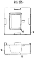
- FIG. 1(b) is a section along line A-A of Figure 1(a), there is shown a diffusion bonding pack.
- the pack comprises a stack of two outer or face sheets 1 of 8090 aluminium-lithium alloy, a core sheet 1′ also made of 8090 aluminium-lithium alloy, the core sheet 1′ being separated from the face sheets 1 by two thin masks 2 formed of glass cloth.
- the stack of alloy sheets is sandwiched between spacer elements 3, and is located in the cavity 15 in the base 16 of a press 17 between a base element 4 and an upper diaphragm 5, which is made of a superplastic material.
- the alloy sheets 1,1′ and the glass cloth masks 2 are pretreated.
- the sheets are chemically cleaned and the surfaces to be bonded are grit blasted using aluminium oxide.
- the glass masks are pre-baked at 590°C for one hour to drive off any organic binders or other possible contaminants.
- the outer two alloy sheets 1 are uninterrupted squares or rectangles, but the inner or core sheet 1′, as shown in Figure 2(a), has two cut-away portions 6 which are partly complementary in shape to the two masks 2 that are shown in Figures 2(b) and 2(c).
- Figure 2(b) shows the upper of the two masks (as viewed in in Figure 1(b)), and Figure 2(c) the lower of the pair. It will be appreciated that when the alloy sheets and masks are superimposed in the bonding pack, the masks will prevent bonding of the alloy sheets in selected locations by stopping the sheets from contacting one another.
- the shapes of the masks 2 and the core sheet 1′ are shown by broken lines in Figure 1(a).
- the prepared sheets are formed into the bonding pack along with the glass cloth masks as shown in Figure 1(b).
- the bonding pack is then loaded into the cavity 15 of the press which is preheated to 560°C, the membrane is placed over the pack and the press is sealed by clamping the top 18 of the press against the base 16 thereby copmpressing the edges of the membrane 5 and sealing the cavity 15. Whilst heating up to the required bonding temperature, the cavity 15 is evacuated for 10 minutes to achieve a vacuum of 10 ⁇ 6 mbar or better. This evacuation is carried out via a vacuum pipe 7 passing through the wall of the base 16 and connected to a pump (not shown).
- a bonding pressure of 1000 psi (7 MPa) is applied to the pack by supplying pressurised gas through inlet 8 to the space 14 above the diaphragm 5.
- the bonding pressure and temperature are maintained for as long as is necessary to achieve diffusion bonding; typically a period of 3 hours. After diffusion bonding has taken place, the pack is removed from the press and allowed to cool.
- a gas-supply hole 19 (see Figure 4) is drilled in the pack of bonded sheets (the shapes of the masks 2 and of the core sheet 1′ are shown by broken lines in Figure 4); the hole 19 passes through a tail part 6′ in the cut-out section 6 of the core sheet 1′ (see also Figure 2(a)) and through a tail part 2′ in the stop-off masks 2 (see also Figure 2(b) and (c)) to allow gas to be injected into the interior of the pack, as described in more detail below; the hole 19 does not, however, extend all the way through the stack of sheets and does not pass through the lower face sheet 1.
- the pack is then loaded into the superplastic forming (SPF) tooling shown in Figures 3(a) and (b).
- SPPF superplastic forming
- the SPF tooling includes an upper tool part 9, shown in Figure 3(a), and a lower tool part 10 shown in Figure 3(b).
- the upper tool part 9 is provided with a supply line 11 for the supply of an inert gas, such as argon or compressed air, to the diffusion bonded pack during the SPF step; the outlet 11′ of the gas supply line 11 is located in register with the above-described gas-supply hole 19 that has been drilled in the pack.
- the lower tool part 10 is formed with an internal surface 12 corresponding to the outer surface of the structure to be formed.
- the tool After the bonded stack has been loaded into the SPF tool, the tool is placed in a preheated press (530°C) and the temperature allowed to stabilise (which takes approximately 20 minutes). Compressed air is then injected into the interior of the pack via supply line 11 and the gas-supply hole 19 drilled in the pack, the gas pressure being controlled to produce an optimum pressure-time cycle which may be calculated in advance using computer modelling techniques.
- a preheated press 530°C
- stabilise which takes approximately 20 minutes
- Compressed air is then injected into the interior of the pack via supply line 11 and the gas-supply hole 19 drilled in the pack, the gas pressure being controlled to produce an optimum pressure-time cycle which may be calculated in advance using computer modelling techniques.
- FIG. 5 shows in section the structure obtained with the sheets and masks of Figures 1 and 2.
Description
- This invention relates to diffusion bonding and in particular to a stop-off material for use in the production of combined diffusion bonded and superplastically formed structures which are preferably made of aluminium or an aluminium alloy
- Combined diffusion bonding and superplastic forming (DB/SPF) has recently become established as a production technique, in particular with titanium alloys. To summarise the DB/SPF process: several sheets of a superplastic metal or alloy are formed into a stack and compressed at high temperature and pressures until the sheets are diffusion bonded together. In selected locations, a stop-off material is applied to the sheets to prevent bonding in these locations while permitting bonding at the remaining locations. After diffusion bonding, and also at high temperature, the superplastic forming step is conducted that is to say an inert gas is supplied under high pressure to the interior of the stack so as to 'inflate' the sheets into a three-dimensional structure. As is well known, the shape and structure of the final product is dependant on, amongst other things, the number of sheets in the stack and the location of the stop-off material.
- In DB/SPF of titanium alloys a suitable stop-off material is fine particles of yttria in an organic resin binder, which may be applied to the sheets by conventional silk-screen printing techniques (see for
example GB 2 095 137 and 1 495 655). During the DB step, which is carried out at a temperature greater than 900°C for titanium, evaporation of the binder can contaminate the surfaces of the alloy sheets; similar problems occur in the diffusion bonding of aluminium aloys. In order to produce structures, particularly those made of an aluminium base alloy, by DB/SPF techniques satisfactorily, there remains the need for a suitable stop-off material. - DE-A-37 10 680 describes a process of explosion bonding foils in a packet; paper or fibre sheets can be interposed between the sheets to prevent bonding in the areas covered by the sheets.
- EP-A-0 350 220 describes a process of diffusion bonding aluminium components together after a surface treatment to improve diffusion bonding. There is an example of using a glass cloth as a stop-off material.
- According to the invention there is provided a method of forming a structure, which method comprises arranging a plurality of sheets of a superplastic metal (e.g. aluminium or an aluminium alloy) in a stack, interposing a lamella of inert porous material between adjacent sheets in a predetermined pattern to prevent bonding between said adjacent sheets in selected regions, diffusion bonding said stack of sheets together and then subjecting the thus bonded stack to superplastic forming.
- The interposed lamella must meet certain requirements to act as a successful stop-off material. The material must be inert at the elevated temperatures concerned, typically in the region of 500 to 600°C depending on the alloy. In addition, the material must be porous to permit gas to flow between the alloy sheets during the SPF step. Examples of suitable materials are glass cloth and vermiculite paper.
- It is preferred to preheat the lamella(e) prior to said diffusion bonding to drive off any possible contaminants and preferably this is achieved at a temperature above the temperature used in the diffusion bonding step. It is also preferred that prior to the diffusion bonding step, the stack of alloy sheets and interposed lamella(e) is sealed under vacuum.
- Suitable aluminium alloys are any that exhibit superplastic properties, and in particular aluminium-lithium alloys such as 8090 aluminium-lithium.
- In contrast to the prior art, the present invention achieves the stopping-off of the superplastic sheets by the simple expedient of placing a self-supporting lamella of inert porous stop-off material between adjacent sheets prior to the diffusion bonding step and so does away with the necessarity of applying stop-off material in a liquid vehicle, e.g. by silk screen printing, and so avoids the consequent problems of contamination by the liquid vehicle used in such printing.
- An embodiment of the invention will now be described by way of example and with reference to the accompanying drawings, in which:-
- Figures 1(a) and (b) are views in plan and section respectively of an apparatus for the diffusion bonding of a stack of alloy sheets;
- Figures 2(a), (b) and (c) are plan views of an alloy core sheet and two stop-off masks, respectively;
- Figures 3(a) and (b) are views of upper and lower superplastic forming tools;
- Figure 4 is a plan view of a diffusion bonded stack ready for superplastic forming; and
- Figure 5 is section through a structure formed by the process of the present invention.
- Referring firstly to Figure 1(b), which is a section along line A-A of Figure 1(a), there is shown a diffusion bonding pack. The pack comprises a stack of two outer or
face sheets 1 of 8090 aluminium-lithium alloy, acore sheet 1′ also made of 8090 aluminium-lithium alloy, thecore sheet 1′ being separated from theface sheets 1 by twothin masks 2 formed of glass cloth. The stack of alloy sheets is sandwiched betweenspacer elements 3, and is located in thecavity 15 in thebase 16 of a press 17 between a base element 4 and anupper diaphragm 5, which is made of a superplastic material. - Before being formed into the bonding pack as shown in Figure 1, the
alloy sheets glass cloth masks 2 are pretreated. In particular the sheets are chemically cleaned and the surfaces to be bonded are grit blasted using aluminium oxide. The glass masks are pre-baked at 590°C for one hour to drive off any organic binders or other possible contaminants. - The outer two
alloy sheets 1 are uninterrupted squares or rectangles, but the inner orcore sheet 1′, as shown in Figure 2(a), has two cut-awayportions 6 which are partly complementary in shape to the twomasks 2 that are shown in Figures 2(b) and 2(c). Figure 2(b) shows the upper of the two masks (as viewed in in Figure 1(b)), and Figure 2(c) the lower of the pair. It will be appreciated that when the alloy sheets and masks are superimposed in the bonding pack, the masks will prevent bonding of the alloy sheets in selected locations by stopping the sheets from contacting one another. The shapes of themasks 2 and thecore sheet 1′ are shown by broken lines in Figure 1(a). - The prepared sheets are formed into the bonding pack along with the glass cloth masks as shown in Figure 1(b). The bonding pack is then loaded into the
cavity 15 of the press which is preheated to 560°C, the membrane is placed over the pack and the press is sealed by clamping thetop 18 of the press against thebase 16 thereby copmpressing the edges of themembrane 5 and sealing thecavity 15. Whilst heating up to the required bonding temperature, thecavity 15 is evacuated for 10 minutes to achieve a vacuum of 10⁻⁶ mbar or better. This evacuation is carried out via a vacuum pipe 7 passing through the wall of thebase 16 and connected to a pump (not shown). - After the pack has reached the required temperature, a bonding pressure of 1000 psi (7 MPa) is applied to the pack by supplying pressurised gas through
inlet 8 to thespace 14 above thediaphragm 5. The bonding pressure and temperature are maintained for as long as is necessary to achieve diffusion bonding; typically a period of 3 hours. After diffusion bonding has taken place, the pack is removed from the press and allowed to cool. - After cooling, a gas-supply hole 19 (see Figure 4) is drilled in the pack of bonded sheets (the shapes of the
masks 2 and of thecore sheet 1′ are shown by broken lines in Figure 4); thehole 19 passes through atail part 6′ in the cut-outsection 6 of thecore sheet 1′ (see also Figure 2(a)) and through atail part 2′ in the stop-off masks 2 (see also Figure 2(b) and (c)) to allow gas to be injected into the interior of the pack, as described in more detail below; thehole 19 does not, however, extend all the way through the stack of sheets and does not pass through thelower face sheet 1. The pack is then loaded into the superplastic forming (SPF) tooling shown in Figures 3(a) and (b). The SPF tooling includes anupper tool part 9, shown in Figure 3(a), and alower tool part 10 shown in Figure 3(b). Theupper tool part 9 is provided with asupply line 11 for the supply of an inert gas, such as argon or compressed air, to the diffusion bonded pack during the SPF step; theoutlet 11′ of thegas supply line 11 is located in register with the above-described gas-supply hole 19 that has been drilled in the pack. Thelower tool part 10 is formed with aninternal surface 12 corresponding to the outer surface of the structure to be formed. - After the bonded stack has been loaded into the SPF tool, the tool is placed in a preheated press (530°C) and the temperature allowed to stabilise (which takes approximately 20 minutes). Compressed air is then injected into the interior of the pack via
supply line 11 and the gas-supply hole 19 drilled in the pack, the gas pressure being controlled to produce an optimum pressure-time cycle which may be calculated in advance using computer modelling techniques. - The porous nature of the masks allows the gas under pressure to permeate from the gas-
supply hole 19 to the interface between the sheets of the bonded stack where they are not bonded, and the gas pressure, in conjunction with the high temperature, causes the stack to inflate superplastically into therecess 12 formed in thelower tool 10 until the final structure is obtained, which is then allowed to cool. Figure 5 shows in section the structure obtained with the sheets and masks of Figures 1 and 2. - In addition to the above method it may be advisable to seal the stack under vacuum prior to diffusion bonding by means of electron beam welding. This would reduce the possibility of the porous lamellar masks trapping appreciable quantities of air that would result in the subsequent formation of undesirable oxides. Such sealing would also increase substantially the 'shelf-life' of the stacks of sheets once they have been cleaned and prepared for bonding, that is to say the time between, on the one hand, the pre-treatment of the alloy sheets and the assembly of the bonding pack and, on the other hand, the diffusion bonding of the pack. Furthermore, such sealing of the sheets under vacuum prior to bonding would allow for the option of carrying out the diffusion bonding by hot isostatic pressure techniques (HIP).
Claims (10)
- A method of forming a structure, which method comprises arranging a plurality of sheets (1, 1') of a superplastic metal in a stack, interposing inert stop-off material between adjacent sheets in a predetermined pattern to prevent bonding between said adjacent sheets in selected regions, diffusion bonding said stack of sheets together and then subjecting the thus bonded stack to superplastic forming, characterised in that the interposed inert stop-off material is a lamella (3) of porous material
but subject to the constraint that the stop-off material is not a glass cloth when(1) at least one of the sheets is made of aluminium or an aluminium alloy and which is liable to form a surface coating of aluminium oxide and(2) prior to arranging the sheets in a stack, the sheet(s) made of aluminium or aluminium alloy are grit blasted in areas that are to be bonded to other sheets, and(3) prior to arranging the sheets in a stack, the grit blasted sheets are chemically treated to remove surface aluminium oxide, and(4) the sheets are diffusion bonded together by heating and pressing them together without substantial plastic deformation of the sheets. - A method according to claim 1, characterised in that said lamella (3) comprises a mat, paper or cloth.
- A method according to claim 1 or claim 2, characterised in that the said lamella of stop-off material (3) comprises a filamentary material.
- A method according to claim 3, characterised in that the lamella (3) of stop-off material comprises a glass cloth.
- A method according to claim 1 or claim 2, characterised in that said lamella of stop-off material (3) comprises vermiculite paper.
- A method according to any preceding claim, characterised in that said lamella of stop-off material (3) is preheated prior to said diffusion bonding to drive off any contaminants.
- A method according to claim 6, characterised in that the said lamella of stop-off material (3) is preheated prior to said diffusion bonding step to a temperature in excess of the temperature of the diffusion bonding step.
- A method according to any preceding claim, characterised in that said stack, prior to said diffusion bonding, is sealed under vacuum, e.g. by means of electron beam welds, around the edge regions of the sheets.
- A method according to any preceding claim, characterised in that the metal is aluminium or an aluminium alloy.
- A method according to claim 9, characterised in that said aluminium alloy is an aluminium-lithium alloy.
Applications Claiming Priority (2)
| Application Number | Priority Date | Filing Date | Title |
|---|---|---|---|
| GB898912025A GB8912025D0 (en) | 1989-05-25 | 1989-05-25 | Diffusion bonding |
| GB8912025 | 1989-05-25 |
Publications (3)
| Publication Number | Publication Date |
|---|---|
| EP0399772A2 EP0399772A2 (en) | 1990-11-28 |
| EP0399772A3 EP0399772A3 (en) | 1991-01-30 |
| EP0399772B1 true EP0399772B1 (en) | 1993-12-15 |
Family
ID=10657325
Family Applications (1)
| Application Number | Title | Priority Date | Filing Date |
|---|---|---|---|
| EP90305514A Expired - Lifetime EP0399772B1 (en) | 1989-05-25 | 1990-05-22 | Diffusion bonding and superplastic forming |
Country Status (5)
| Country | Link |
|---|---|
| US (1) | US5069383A (en) |
| EP (1) | EP0399772B1 (en) |
| DE (1) | DE69005192T2 (en) |
| ES (1) | ES2047263T3 (en) |
| GB (1) | GB8912025D0 (en) |
Families Citing this family (20)
| Publication number | Priority date | Publication date | Assignee | Title |
|---|---|---|---|---|
| GB9026134D0 (en) * | 1990-11-30 | 1991-01-16 | British Aerospace | Explosive bonding |
| US5263638A (en) * | 1991-06-04 | 1993-11-23 | Rolls-Royce Plc | Method of manufacturing an article by superplastic forming and diffusion bonding and a vacuum chamber for use in processing workpieces for superplastic forming and diffusion bonding |
| GB9122874D0 (en) * | 1991-10-29 | 1991-12-11 | Rolls Royce Plc | A method of manufacturing an article,a method of diffusion bonding and a vacuum chamber |
| US5273202A (en) * | 1991-10-29 | 1993-12-28 | Rolls-Royce Plc | Method of manufacturing an article, a method of diffusion bonding and a vacuum chamber |
| GB9205034D0 (en) * | 1992-03-07 | 1992-04-22 | British Aerospace | Manufacture of components by superplastic forming |
| US5715644A (en) * | 1996-08-13 | 1998-02-10 | Mcdonnell Douglas Corporation | Superplastically formed, diffusion bonded panels with diagonal reinforcing webs and method of manufacture |
| US5723225A (en) * | 1996-08-26 | 1998-03-03 | Mcdonnell Douglas Corporation | Superplastically formed, diffusion bonded multiple sheet panels with web doublers and method of manufacture |
| US5904992A (en) * | 1996-09-26 | 1999-05-18 | Mcdonnell Douglas Corporation | Floating superplastic forming/diffusion bonding die, product and process |
| US5737954A (en) * | 1996-11-15 | 1998-04-14 | Mcdonnell Douglas Corporation | Superplastic forming with direct electrical heating |
| US6711898B2 (en) | 1999-04-01 | 2004-03-30 | Parker-Hannifin Corporation | Fuel manifold block and ring with macrolaminate layers |
| US6321541B1 (en) | 1999-04-01 | 2001-11-27 | Parker-Hannifin Corporation | Multi-circuit multi-injection point atomizer |
| US6202277B1 (en) | 1999-10-28 | 2001-03-20 | General Electric Company | Reusable hard tooling for article consolidation and consolidation method |
| FR2852537B1 (en) * | 2003-03-21 | 2005-06-17 | Snecma Moteurs | ASSEMBLY FOR MANUFACTURING A HOLLOW-DIFFUSION HOLLOW MECHANICAL PIECE AND SUPERPLASTIC FORMING, USE OF SUCH AN ASSEMBLY AND METHOD OF MANUFACTURING SUCH A MECHANICAL PIECE |
| US7451907B2 (en) * | 2004-08-06 | 2008-11-18 | General Motors Corporation | Roll bonding of bipolar plates |
| CN100462196C (en) * | 2006-02-27 | 2009-02-18 | 北京亚太空间钛业有限公司 | Laminated titanium-alloy thin-plate assembled connecting method |
| US8727203B2 (en) | 2010-09-16 | 2014-05-20 | Howmedica Osteonics Corp. | Methods for manufacturing porous orthopaedic implants |
| FR2997645B1 (en) * | 2012-11-06 | 2015-05-15 | Technicatome | METHOD AND DEVICE FOR UNI-AXIAL COMPRESSION DIFFUSION WELDING, USE FOR PLATES CARRYING CHANNELS |
| US20140335368A1 (en) * | 2013-05-13 | 2014-11-13 | Ford Global Technologies, Llc | Method Of Fabricating Roll-Bonded Expanded Load-Bearing Aluminum Laminate Structural Elements For Vehicle |
| DE102014111634A1 (en) * | 2014-08-14 | 2016-02-18 | Atv Technologie Gmbh | Device for in particular thermal connection of microelectromechanical components |
| DE102020215873A1 (en) | 2020-12-15 | 2022-06-15 | Forschungszentrum Jülich GmbH | Process for manufacturing assemblies and use of a release agent |
Family Cites Families (11)
| Publication number | Priority date | Publication date | Assignee | Title |
|---|---|---|---|---|
| GB820033A (en) * | 1955-10-03 | 1959-09-16 | Olin Mathieson | A method of applying weld-preventing material to a metal sheet and a metal sheet treated with weld-preventing material |
| GB883359A (en) * | 1958-06-24 | 1961-11-29 | Phoenix Rheinrohr Ag | Improvements in or relating to the cladding of metals |
| GB1495655A (en) * | 1975-03-20 | 1977-12-21 | Rockwell International Corp | Method for making metallic structures from two or more selectively bonded sheets |
| US4197977A (en) * | 1978-04-20 | 1980-04-15 | The Boeing Company | Method of making an actively-cooled titanium structure |
| US4406393A (en) * | 1981-03-23 | 1983-09-27 | Rockwell International Corporation | Method of making filamentary reinforced metallic structures |
| US4426032A (en) * | 1981-09-10 | 1984-01-17 | The United States Of America As Represented By The Secretary Of The Air Force | Tool sealing arrangement and method |
| GB8623719D0 (en) * | 1986-10-02 | 1986-11-05 | British Aerospace | Stop-off compound |
| US4732312A (en) * | 1986-11-10 | 1988-03-22 | Grumman Aerospace Corporation | Method for diffusion bonding of alloys having low solubility oxides |
| DE3710680C1 (en) * | 1987-03-31 | 1988-10-06 | Surtec Patent Holding | Method of producing multi-foils |
| US4942999A (en) * | 1987-08-31 | 1990-07-24 | Ngk Insulators, Inc. | Metal-ceramic joined composite bodies and joining process therefor |
| US4811766A (en) * | 1987-10-08 | 1989-03-14 | Mcdonnell Douglas Corporation | Explosively bonded expanded structure |
-
1989
- 1989-05-25 GB GB898912025A patent/GB8912025D0/en active Pending
-
1990
- 1990-05-22 EP EP90305514A patent/EP0399772B1/en not_active Expired - Lifetime
- 1990-05-22 ES ES90305514T patent/ES2047263T3/en not_active Expired - Lifetime
- 1990-05-22 DE DE90305514T patent/DE69005192T2/en not_active Expired - Fee Related
-
1991
- 1991-04-30 US US07/693,036 patent/US5069383A/en not_active Expired - Fee Related
Also Published As
| Publication number | Publication date |
|---|---|
| DE69005192D1 (en) | 1994-01-27 |
| EP0399772A2 (en) | 1990-11-28 |
| ES2047263T3 (en) | 1994-02-16 |
| EP0399772A3 (en) | 1991-01-30 |
| DE69005192T2 (en) | 1994-03-31 |
| US5069383A (en) | 1991-12-03 |
| GB8912025D0 (en) | 1989-07-12 |
Similar Documents
| Publication | Publication Date | Title |
|---|---|---|
| EP0399772B1 (en) | Diffusion bonding and superplastic forming | |
| KR940009656B1 (en) | Preparation of capsule for use in isostatic pressing treatment | |
| US4406393A (en) | Method of making filamentary reinforced metallic structures | |
| US5024368A (en) | Stopping-off method for use with diffusion bonding | |
| US4426032A (en) | Tool sealing arrangement and method | |
| DE4005674C2 (en) | Method and device for encapsulating a material to be processed by means of hot or hot isostatic pressing | |
| US4811890A (en) | Method of eliminating core distortion in diffusion bonded and uperplastically formed structures | |
| US5611944A (en) | Hollow component manufacture | |
| US5188281A (en) | Brazing procedure in inert atmosphere | |
| US6129261A (en) | Diffusion bonding of metals | |
| US4691857A (en) | Method of shaping a workpiece | |
| US5344063A (en) | Method of making diffusion bonded/superplastically formed cellular structures with a metal matrix composite | |
| US4483478A (en) | Method for fabricating superplastically formed/diffusion bonded aluminum or aluminum alloy structures | |
| EP0398760B1 (en) | Diffussion bonding of aluminium and aluminium alloys | |
| GB2269555A (en) | A method of manufacturing an article by superplastic forming and diffusion bonding | |
| GB2269556A (en) | A method of manufacturing an article by diffusion bonding | |
| US5199631A (en) | Differential pressure method and apparatus for bonding high temperature structures | |
| EP0488592B1 (en) | Explosive bonding | |
| EP1386680B1 (en) | Tooling apparatus for composite fabrication | |
| US5399215A (en) | Method of manufacturing assemblies composed of two bonded parts | |
| US5447668A (en) | Method and apparatus for eliminating fiber distortions and separations in metal matrix materials | |
| JP2803927B2 (en) | Method for manufacturing plate-shaped diffusion bonding member | |
| JPH0736928B2 (en) | Superplastic forming method for metal foil | |
| JP2823411B2 (en) | Diffusion bonding member manufacturing method | |
| US5403423A (en) | Method for forming details and adhesive bonding of sheet metal and composite assemblies |
Legal Events
| Date | Code | Title | Description |
|---|---|---|---|
| PUAI | Public reference made under article 153(3) epc to a published international application that has entered the european phase |
Free format text: ORIGINAL CODE: 0009012 |
|
| AK | Designated contracting states |
Kind code of ref document: A2 Designated state(s): DE ES FR GB IT SE |
|
| PUAL | Search report despatched |
Free format text: ORIGINAL CODE: 0009013 |
|
| AK | Designated contracting states |
Kind code of ref document: A3 Designated state(s): DE ES FR GB IT SE |
|
| 17P | Request for examination filed |
Effective date: 19901221 |
|
| 17Q | First examination report despatched |
Effective date: 19920804 |
|
| RAP3 | Party data changed (applicant data changed or rights of an application transferred) |
Owner name: BRITISH AEROSPACE PUBLIC LIMITED COMPANY |
|
| ITF | It: translation for a ep patent filed |
Owner name: BARZANO' E ZANARDO ROMA S.P.A. |
|
| GRAA | (expected) grant |
Free format text: ORIGINAL CODE: 0009210 |
|
| AK | Designated contracting states |
Kind code of ref document: B1 Designated state(s): DE ES FR GB IT SE |
|
| ET | Fr: translation filed | ||
| REF | Corresponds to: |
Ref document number: 69005192 Country of ref document: DE Date of ref document: 19940127 |
|
| REG | Reference to a national code |
Ref country code: ES Ref legal event code: FG2A Ref document number: 2047263 Country of ref document: ES Kind code of ref document: T3 |
|
| PGFP | Annual fee paid to national office [announced via postgrant information from national office to epo] |
Ref country code: FR Payment date: 19940413 Year of fee payment: 5 |
|
| PGFP | Annual fee paid to national office [announced via postgrant information from national office to epo] |
Ref country code: SE Payment date: 19940419 Year of fee payment: 5 Ref country code: GB Payment date: 19940419 Year of fee payment: 5 |
|
| PGFP | Annual fee paid to national office [announced via postgrant information from national office to epo] |
Ref country code: DE Payment date: 19940425 Year of fee payment: 5 |
|
| PGFP | Annual fee paid to national office [announced via postgrant information from national office to epo] |
Ref country code: ES Payment date: 19940506 Year of fee payment: 5 |
|
| PLBE | No opposition filed within time limit |
Free format text: ORIGINAL CODE: 0009261 |
|
| STAA | Information on the status of an ep patent application or granted ep patent |
Free format text: STATUS: NO OPPOSITION FILED WITHIN TIME LIMIT |
|
| 26N | No opposition filed | ||
| EAL | Se: european patent in force in sweden |
Ref document number: 90305514.3 |
|
| PG25 | Lapsed in a contracting state [announced via postgrant information from national office to epo] |
Ref country code: GB Effective date: 19950522 |
|
| PG25 | Lapsed in a contracting state [announced via postgrant information from national office to epo] |
Ref country code: SE Effective date: 19950523 Ref country code: ES Free format text: LAPSE BECAUSE OF NON-PAYMENT OF DUE FEES Effective date: 19950523 |
|
| GBPC | Gb: european patent ceased through non-payment of renewal fee |
Effective date: 19950522 |
|
| PG25 | Lapsed in a contracting state [announced via postgrant information from national office to epo] |
Ref country code: DE Effective date: 19960201 |
|
| EUG | Se: european patent has lapsed |
Ref document number: 90305514.3 |
|
| PG25 | Lapsed in a contracting state [announced via postgrant information from national office to epo] |
Ref country code: FR Effective date: 19960229 |
|
| REG | Reference to a national code |
Ref country code: FR Ref legal event code: ST |
|
| REG | Reference to a national code |
Ref country code: FR Ref legal event code: ST |
|
| REG | Reference to a national code |
Ref country code: ES Ref legal event code: FD2A Effective date: 19990301 |
|
| PG25 | Lapsed in a contracting state [announced via postgrant information from national office to epo] |
Ref country code: IT Free format text: LAPSE BECAUSE OF NON-PAYMENT OF DUE FEES;WARNING: LAPSES OF ITALIAN PATENTS WITH EFFECTIVE DATE BEFORE 2007 MAY HAVE OCCURRED AT ANY TIME BEFORE 2007. THE CORRECT EFFECTIVE DATE MAY BE DIFFERENT FROM THE ONE RECORDED. Effective date: 20050522 |