EP0399502B1 - Vehicular engine and power train mounting arrangement - Google Patents
Vehicular engine and power train mounting arrangement Download PDFInfo
- Publication number
- EP0399502B1 EP0399502B1 EP90109827A EP90109827A EP0399502B1 EP 0399502 B1 EP0399502 B1 EP 0399502B1 EP 90109827 A EP90109827 A EP 90109827A EP 90109827 A EP90109827 A EP 90109827A EP 0399502 B1 EP0399502 B1 EP 0399502B1
- Authority
- EP
- European Patent Office
- Prior art keywords
- axis
- engine
- vehicle
- rotation
- differential gear
- Prior art date
- Legal status (The legal status is an assumption and is not a legal conclusion. Google has not performed a legal analysis and makes no representation as to the accuracy of the status listed.)
- Expired - Lifetime
Links
Images


Classifications
-
- B—PERFORMING OPERATIONS; TRANSPORTING
- B60—VEHICLES IN GENERAL
- B60K—ARRANGEMENT OR MOUNTING OF PROPULSION UNITS OR OF TRANSMISSIONS IN VEHICLES; ARRANGEMENT OR MOUNTING OF PLURAL DIVERSE PRIME-MOVERS IN VEHICLES; AUXILIARY DRIVES FOR VEHICLES; INSTRUMENTATION OR DASHBOARDS FOR VEHICLES; ARRANGEMENTS IN CONNECTION WITH COOLING, AIR INTAKE, GAS EXHAUST OR FUEL SUPPLY OF PROPULSION UNITS IN VEHICLES
- B60K5/00—Arrangement or mounting of internal-combustion or jet-propulsion units
- B60K5/04—Arrangement or mounting of internal-combustion or jet-propulsion units with the engine main axis, e.g. crankshaft axis, transversely to the longitudinal centre line of the vehicle
-
- Y—GENERAL TAGGING OF NEW TECHNOLOGICAL DEVELOPMENTS; GENERAL TAGGING OF CROSS-SECTIONAL TECHNOLOGIES SPANNING OVER SEVERAL SECTIONS OF THE IPC; TECHNICAL SUBJECTS COVERED BY FORMER USPC CROSS-REFERENCE ART COLLECTIONS [XRACs] AND DIGESTS
- Y10—TECHNICAL SUBJECTS COVERED BY FORMER USPC
- Y10T—TECHNICAL SUBJECTS COVERED BY FORMER US CLASSIFICATION
- Y10T74/00—Machine element or mechanism
- Y10T74/21—Elements
- Y10T74/2186—Gear casings
Definitions
- the invention relates to a power train arrangement for an automotive vehicle as indicated in the precharacterizing part of claim 1.
- a mounting arrangement for an automotive vehicle with transversely disposed engine, transmission and differential gear unit according to the preamble of claim 1 is known in the art as disclosed, for example, in DE-A-19 63 019.
- a transfer unit is further disposed adjacent to the differential gear unit with its axis being aligned with the axis of the differential gear unit for a power transmission therefrom. Accordingly, a location of the transfer unit is caused to be offset or deviated laterally from the lateral center of the vehicle.
- the transfer unit controls a power distribution to be transmitted to rear wheels through a propeller shaft and a rear wheel differential gear unit.
- the propeller shaft extends axially between the transfer unit and the rear wheel differential gear unit.
- the propeller shaft is inevitably offset or deviated laterally from the lateral center of the vehicle, so that no space for a brake pedal is provided at one lateral side of the vehicle due to existence of a floor projection or tunnel for accommodating the offset propeller shaft underneath a vehicle floor. Accordingly, a problem has been raised that the same layout of the foregoing vehicular components can not satisfy both right and left steering wheel vehicles due to no space of the brake pedal at the one lateral side of the vehicle.
- the differential gear unit is disposed at the rear of the transmission gear train so as to arrange the propeller shaft to extend axially at the lateral center of the vehicle, a problem is raised that a weight distribution to front wheels increases to deteriorate controllability of the steering wheel as well as durability of front tires due to an inevitable forward location change of the engine, which location is far forward of axes of the front wheels, and due to a corresponding increased front overhang.
- a mounting arrangement of a vehicular engine and an associated power train is provided that, when applied to a four wheel drive vehicle, can prevent a lateral deviation or offset of a location of a propeller shaft from the lateral centre of the vehicle, that can minimize a weight distribution to front wheels as well as a front overhang while satisfying other requirements, and that can allow a lower engine hood line while satisfying other requirements.
- Figs. 1 and 2 respectively show a front side of a four wheel drive vehicle.
- a gear train 4 of a transmission with its axis Z extending transversely to a longitudial axis of the vehicle or extending in a width direction of the vehicle.
- An oil pump 6 is further provided underneath the transmission gear train 4.
- a reference numeral 8 designates a radiator which is arranged forward of the sub-frame 2.
- a differential gear unit 10 is mounted rearward of the transmission gear train 4 at a left side of the vehicle with its axis Y extending in parallel with the axis Z of the transmission gear train 4.
- the differential gear unit 4 is connected to the transmission gear train 4 through an idler gear unit 12 for a power transmission from the transmission gear train 4.
- An engine 14 is disposed with an axis X of an engine crankshaft extending in parallel with the axes Y and Z of the respective differential gear unit 10 and transmission gear train 4.
- the axis X of the engine crankshaft is located rearward of the axis Z of the transmission gear train 4 and above the axis Y of the differential gear unit 10 substantially in a vertical direction.
- the engine 14 is a six-cylinder in-line type engine with the cylinders 16 inclined forward and is supported by the sub-frame 2 through four engine mountings 18 one of which is illustrated in detail in a circle in Fig. 1 as an example.
- An engine oil pan 20 is fixed to a slanted rear end or lower end of a cylinder block. Space for the engine oil pan 20 is sufficiently ensured due to the forward inclined arrangement of the engine cylinders 16.
- Reference numerals 22 and 24 respectively show a lower link and a tension rod of a suspension unit which is provided at both lateral sides of the sub-frame 2.
- a torque converter 26 is provided on the left of the engine 14 with its axis being aligned with the axis X of the engine crankshaft for a power transmission from the latter.
- the torque converter 26 and the transmission gear train 4 are connected through, for example, a sprocket-chain connection 27 therebetween.
- a transfer unit 28 is further disposed on the right of the differential gear unit 10 with its axis being aligned with the axis Y of the differential gear unit 10 for a power transmission from the latter.
- the transfer unit 28 controls a power distribution to be transmitted to rear wheels through a propeller shaft 30 and a rear wheel differential gear unit (not shown).
- the propeller shaft 30 extends axially rearward from the transfer unit 28 at the lateral center of the vehicle.
- Reference numerals 32 and 34 respectively denote a brake pedal and an accelerator pedal, and reference numerals 36 and 38 denote a rack-and-pinion steering gear of a steering mechanism.
- the differential gear unit 10 and the transmission gear train 4 are arranged in parallel with one another, a degree of freedom for the layout in the width direction of the vehicle is increased. Accordingly, the layout of, for example, the lower link 22 and the tension rod 24 of the suspension system becomes more flexible. Further, an engine having a larger number of cylinders, such as, an eight-cylinder in-line type engine can be easily installed.
- the transfer unit 28 can be arranged at the lateral center of the vehicle
- the propeller shaft 30 can also be arranged to extend axially rearward from the transfer unit 28 at the lateral center of the vehicle. Accordingly, sufficient space for the brake pedal 32 and the accelerator pedal 34 is ensured at both lateral sides of the vehicle.
- axis X of the engine crankshaft is located rearward of the axis Z of the transmission gear train 4, a weight distribution to front wheels is made less in comparison with the aforementioned background art to improve controllability of the steering wheel as well as the durability of the front tires.
- the rearward location of the axis X of the engine crankshaft relative to the axis Z of the transmission gear train 4 allows the engine cylinders 16 to be inclined forward in view of the front overhang, so that a lower engine hood line is successfully attained.
- a point A shows a resonance frequency derived in the aforementioned preferred embodiment
- a point B shows a resonance frequency derived in the aforementioned background art in which the axis of the engine crankshaft is arranged above and forward of the axis of the transmission gear train, and the axis of the differential gear unit is arranged rearward of and level with the axis of the transmission gear train.
- the point B of the background art is set within the practical engine revolution speed range
- the point A of the preferred embodiment is set out of the practical engine revolution speed range.
- V-type engine having forward and rearward inclined cylinders may be employed as shown by dotted lines in Figs. 1 and 2.
- the V-type engine can be installed in the normal posture or in a posture with the forward inclined cylinders more inclined forward or with the rearward inclined cylinders more inclined rearward according to a relative engine layout with other vehicular components.
- the degree of freedom for the layout in the width direction of the vehicle is sufficiently large as mentioned above to allow the V-type engine to be installed in a predetermined limited lateral space with the cylinders not interfering with a booster of a brake mechanism, such as, a Master vac 42. Accordingly, the engine can be arranged as close to the dash panel 40 as possible to provide the minimum front overhang. Further, the lateral space for the Master vac 42 is sufficiently' provided at both lateral sides of the engine 14 to allow either a right or left steering wheel with the same layout of the engine. Still further, assuming that the vehicle is hit from front with the engine displaced rearward, the engine is supported evenly on large dimentions of the dash panel 40 with no interference with the Master vac 42, resulting in minimum deformation of the dash panel 40.
- the present invention may also be applicable to a manual transmission vehicle in place of the automatic transmission vehicle as in the preferred embodiment.
- the torque converter 26 may be replaced by a manually operated clutch unit.
- the present invention may also be applicable to a front-engine front-drive vehicle in place of the four wheel drive vehicle as in the preferred embodiment.
Description
- The invention relates to a power train arrangement for an automotive vehicle as indicated in the precharacterizing part of
claim 1. - A mounting arrangement for an automotive vehicle with transversely disposed engine, transmission and differential gear unit according to the preamble of
claim 1 is known in the art as disclosed, for example, in DE-A-19 63 019. - In the prior art arrangement according to US-A-4 223 569 and engine is disposed at the front of a front wheel or four wheel drive vehicle with an axis of an engine crankshaft extending transversely to a longitudinal axis of the vehicle. A torque converter is arranged adjacent to the engine with its axis being aligned with the axis of the engine crankshaft for a power transmission therefrom. At the front of the engine and the torque converter, a gear train of a transmission is disposed with its axis parallel to the axis of the engine crankshaft or the torque converter. An output power of the torque converter is transmitted to an input shaft of the transmission gear train by means of a sprocket-chain connection therebetween. Further, a differential gear unit is disposed at the rear of the transmission gear train and the engine with its axis being aligned with the axis of the transmission gear train for a power transmission therefrom.
- In the above-noted mounting arrangement, however, since the transmission gear train and the differential gear unit are transversely arranged with their axes being aligned with each other, a degree of freedom for mounting other vehicular components, such as various components of a suspension system, is so limited in a transverse or width direction of the vehicle.
- Further, when the above-noted mounting arrangement is applied to a four wheel drive vehicle, a transfer unit is further disposed adjacent to the differential gear unit with its axis being aligned with the axis of the differential gear unit for a power transmission therefrom. Accordingly, a location of the transfer unit is caused to be offset or deviated laterally from the lateral center of the vehicle. The transfer unit controls a power distribution to be transmitted to rear wheels through a propeller shaft and a rear wheel differential gear unit. The propeller shaft extends axially between the transfer unit and the rear wheel differential gear unit. As a result, the propeller shaft is inevitably offset or deviated laterally from the lateral center of the vehicle, so that no space for a brake pedal is provided at one lateral side of the vehicle due to existence of a floor projection or tunnel for accommodating the offset propeller shaft underneath a vehicle floor. Accordingly, a problem has been raised that the same layout of the foregoing vehicular components can not satisfy both right and left steering wheel vehicles due to no space of the brake pedal at the one lateral side of the vehicle.
- On the other hand, if the differential gear unit is disposed at the rear of the transmission gear train so as to arrange the propeller shaft to extend axially at the lateral center of the vehicle, a problem is raised that a weight distribution to front wheels increases to deteriorate controllability of the steering wheel as well as durability of front tires due to an inevitable forward location change of the engine, which location is far forward of axes of the front wheels, and due to a corresponding increased front overhang.
- Another mounting arrangement has been proposed, wherein the axis of the engine crankshaft is arranged above and forward of the axis of the transmission gear train, and the axis of the differential gear unit is arranged rearward of and level with the axis of the transmission gear train. In this arrangement, however, since the engine is still inevitably located considerably forward of the axes of the front wheels, a corresponding large weight distribution to the front wheels as well as the corresponding increased overhang are resulted. In addition, since the engine is located substantially over the transmission gear train, a higher engine hood line is resulted to narrow front visibility, and further, insufficient space for an engine oil pan is resulted.
- Therefore, it is the object of the invention to provide a power train arrangement of a vehicular engine that can increase a degree of freedom for mounting other vehicular components, such as, various components of a suspension system in a transverse or width direction of the vehicle.
- This object is solved by the features as claimed in the characterizing part of
claim 1. In accordance with the invention a mounting arrangement of a vehicular engine and an associated power train is provided that, when applied to a four wheel drive vehicle, can prevent a lateral deviation or offset of a location of a propeller shaft from the lateral centre of the vehicle, that can minimize a weight distribution to front wheels as well as a front overhang while satisfying other requirements, and that can allow a lower engine hood line while satisfying other requirements. - The present invention will be understood more fully from the detailed description given hereinbelow and from the accompanying drawings of the preferred embodiment of the invention, which are given by way of example only, and are not intended to be limitative of the present invention.
- In the drawings:
- Fig. 1 is a schematic diagram viewing from a left side of a vehicle and showing relative locations of vehicular components according to a preferred embodiment of the present invention;
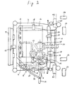
- Fig. 2 is a schematic plan view of Fig. 1; and
- Fig. 3 is a graph showing resonance frequencies derived by the preferred embodiment of Fig. 1 and the background art, relative to engine revolution speed and secondary engine vibration frequency.
- Now, a mounting arrangement of an engine and an associated power train for an automotive vehicle according to a preferred embodiment of the present invention will be described hereinbelow with reference to Figs. 1 and 2.
- Figs. 1 and 2 respectively show a front side of a four wheel drive vehicle. At a front and left side of a
ladder type sub-frame 2 is mounted agear train 4 of a transmission with its axis Z extending transversely to a longitudial axis of the vehicle or extending in a width direction of the vehicle. An oil pump 6 is further provided underneath thetransmission gear train 4. A reference numeral 8 designates a radiator which is arranged forward of thesub-frame 2. - A
differential gear unit 10 is mounted rearward of thetransmission gear train 4 at a left side of the vehicle with its axis Y extending in parallel with the axis Z of thetransmission gear train 4. Thedifferential gear unit 4 is connected to thetransmission gear train 4 through anidler gear unit 12 for a power transmission from thetransmission gear train 4. - An
engine 14 is disposed with an axis X of an engine crankshaft extending in parallel with the axes Y and Z of the respectivedifferential gear unit 10 andtransmission gear train 4. The axis X of the engine crankshaft is located rearward of the axis Z of thetransmission gear train 4 and above the axis Y of thedifferential gear unit 10 substantially in a vertical direction. Theengine 14 is a six-cylinder in-line type engine with thecylinders 16 inclined forward and is supported by thesub-frame 2 through fourengine mountings 18 one of which is illustrated in detail in a circle in Fig. 1 as an example. Anengine oil pan 20 is fixed to a slanted rear end or lower end of a cylinder block. Space for theengine oil pan 20 is sufficiently ensured due to the forward inclined arrangement of theengine cylinders 16. -
Reference numerals sub-frame 2. - A
torque converter 26 is provided on the left of theengine 14 with its axis being aligned with the axis X of the engine crankshaft for a power transmission from the latter. Thetorque converter 26 and thetransmission gear train 4 are connected through, for example, a sprocket-chain connection 27 therebetween. - A
transfer unit 28 is further disposed on the right of thedifferential gear unit 10 with its axis being aligned with the axis Y of thedifferential gear unit 10 for a power transmission from the latter. Thetransfer unit 28 controls a power distribution to be transmitted to rear wheels through apropeller shaft 30 and a rear wheel differential gear unit (not shown). As seen from Fig. 2, thepropeller shaft 30 extends axially rearward from thetransfer unit 28 at the lateral center of the vehicle.Reference numerals reference numerals - In the preferred embodiment as described above, since the axes X, Y and Z of the engine crankshaft, the
differential gear unit 10 and thetransmission gear train 4 are arranged in parallel with one another, a degree of freedom for the layout in the width direction of the vehicle is increased. Accordingly, the layout of, for example, thelower link 22 and thetension rod 24 of the suspension system becomes more flexible. Further, an engine having a larger number of cylinders, such as, an eight-cylinder in-line type engine can be easily installed. - Further, since the
transfer unit 28 can be arranged at the lateral center of the vehicle, thepropeller shaft 30 can also be arranged to extend axially rearward from thetransfer unit 28 at the lateral center of the vehicle. Accordingly, sufficient space for thebrake pedal 32 and theaccelerator pedal 34 is ensured at both lateral sides of the vehicle. - Further, since the axis X of the engine crankshaft is located rearward of the axis Z of the
transmission gear train 4, a weight distribution to front wheels is made less in comparison with the aforementioned background art to improve controllability of the steering wheel as well as the durability of the front tires. - Still further, the rearward location of the axis X of the engine crankshaft relative to the axis Z of the
transmission gear train 4 allows theengine cylinders 16 to be inclined forward in view of the front overhang, so that a lower engine hood line is successfully attained. - Further, since the relative location of the
engine 14 as described above as well as the forward inclined arrangement of theengine cylinders 16 allow the cylinder block of theengine 14 to be fixedly connected to a casing of thetransmission gear train 4 and to a casing of thedifferential gear unit 10 in addition to a secure connection to a casing of thetorque converter 26, a connection rigidity of theengine 14 with the foregoing associated components becomes large enough to shift a resonance frequecy out of a frequency band of a secondary engine vibration derived by a practical engine revolution speed range, which is illustrated in Fig. 3. In Fig. 3, a point A shows a resonance frequency derived in the aforementioned preferred embodiment, and a point B shows a resonance frequency derived in the aforementioned background art in which the axis of the engine crankshaft is arranged above and forward of the axis of the transmission gear train, and the axis of the differential gear unit is arranged rearward of and level with the axis of the transmission gear train. As clearly seen from Fig. 3, the point B of the background art is set within the practical engine revolution speed range, while the point A of the preferred embodiment is set out of the practical engine revolution speed range. - It is to be appreciated that in place of the in-line cylinder type engine, other types of engines, such as, a V-type engine having forward and rearward inclined cylinders may be employed as shown by dotted lines in Figs. 1 and 2. The V-type engine can be installed in the normal posture or in a posture with the forward inclined cylinders more inclined forward or with the rearward inclined cylinders more inclined rearward according to a relative engine layout with other vehicular components.
- When the V-type engine is installed in place of the in-line cylinder type engine, though the rearward
inclined cylinders 16 inevitably approach close to adash panel 40, the degree of freedom for the layout in the width direction of the vehicle is sufficiently large as mentioned above to allow the V-type engine to be installed in a predetermined limited lateral space with the cylinders not interfering with a booster of a brake mechanism, such as, aMaster vac 42. Accordingly, the engine can be arranged as close to thedash panel 40 as possible to provide the minimum front overhang. Further, the lateral space for the Mastervac 42 is sufficiently' provided at both lateral sides of theengine 14 to allow either a right or left steering wheel with the same layout of the engine. Still further, assuming that the vehicle is hit from front with the engine displaced rearward, the engine is supported evenly on large dimentions of thedash panel 40 with no interference with theMaster vac 42, resulting in minimum deformation of thedash panel 40. - For example, the present invention may also be applicable to a manual transmission vehicle in place of the automatic transmission vehicle as in the preferred embodiment. In this case, the
torque converter 26 may be replaced by a manually operated clutch unit. Further, the present invention may also be applicable to a front-engine front-drive vehicle in place of the four wheel drive vehicle as in the preferred embodiment.
Claims (3)
- A power train arrangement mounted in a front engine compartment of an automotive vehicle having a longitudinal axis, comprising:
a transverse engine (14) including an engine block and a cylinder head (16), said cylinder head (16) being disposed forward of said engine block with respect to the forward travel direction of the automotive vehicle, the transverse engine (14) being transversely mounted in the front engine compartment and having a crankshaft with a cranckshaft axis (X) extending transversely to the longitudinal axis of the vehicle;
a transmission gear train (4) drivingly connected to said cranckshaft and having an axis of rotation (Z) extending in parallel to and below the cranckshaft axis ;
a differential gear unit (10) drivingly connected to said transmission gear train (4) and having an axis of rotation (Y) extending in parallel to and below said cranckshaft axis;
a transfer unit (28) drivingly connected to said differential gear unit (10),
characterized in that
said transverse engine (14) is inclined about said cranckshaft axis (X) in a forward travel direction of the automotive vehicle, said axis of rotation (Z) of said transmission gear train (4) is disposed forward of said crankshaft axis (X) with respect to the forward travel direction of the automotive vehicle, and said axis of rotation (Y) of said differential gear unit (10) is disposed rearward of said cranckshaft axis (X) with respect to the forward travel direction of the automotive vehicle; and in that
the transfer unit (28) has an axis of rotation in alignment with said axis of rotation (Y) of said differential gear unit (10). - A power train arrangement as claimed in claim 1,
characterized in that
a torque converter (26) drivingly connected to said crankshaft has an axis of rotation in alignment with said crankshaft axis (X). - A power train arrangement as claimed in claim 1 or 2,
characterized in that
a propeller shaft (3) drivingly connected to said transfer unit (28) extends rearward from said transfer unit (28), with respect to the forward travel of the automotive vehicle.
Applications Claiming Priority (2)
| Application Number | Priority Date | Filing Date | Title |
|---|---|---|---|
| JP130393/89 | 1989-05-24 | ||
| JP1130393A JPH02310128A (en) | 1989-05-24 | 1989-05-24 | Configuration of engine and power transmission |
Publications (2)
| Publication Number | Publication Date |
|---|---|
| EP0399502A1 EP0399502A1 (en) | 1990-11-28 |
| EP0399502B1 true EP0399502B1 (en) | 1993-07-28 |
Family
ID=15033241
Family Applications (1)
| Application Number | Title | Priority Date | Filing Date |
|---|---|---|---|
| EP90109827A Expired - Lifetime EP0399502B1 (en) | 1989-05-24 | 1990-05-23 | Vehicular engine and power train mounting arrangement |
Country Status (4)
| Country | Link |
|---|---|
| US (1) | US5156070A (en) |
| EP (1) | EP0399502B1 (en) |
| JP (1) | JPH02310128A (en) |
| DE (1) | DE69002394T2 (en) |
Families Citing this family (10)
| Publication number | Priority date | Publication date | Assignee | Title |
|---|---|---|---|---|
| JPH05139173A (en) * | 1991-11-20 | 1993-06-08 | Mazda Motor Corp | Power train structure of vehicle |
| US5197792A (en) * | 1992-04-21 | 1993-03-30 | General Motors Corporation | Illuminator device for a display panel |
| DE4421926C2 (en) * | 1994-06-23 | 1996-09-12 | Ford Werke Ag | Gear unit for motor vehicles, in particular with front-wheel drive |
| US5908366A (en) * | 1997-01-06 | 1999-06-01 | Weismann; Christopher A. | Drive train for a vehicle |
| US7287621B2 (en) * | 2002-12-20 | 2007-10-30 | Honda Motor Co., Ltd. | Vehicular power transmission mechanism |
| JP4287136B2 (en) * | 2002-12-20 | 2009-07-01 | 本田技研工業株式会社 | Vehicle suspension arrangement structure |
| US7195644B2 (en) * | 2004-03-02 | 2007-03-27 | Joint Synergy, Llc | Ball and dual socket joint |
| JP2011105282A (en) * | 2009-11-20 | 2011-06-02 | Gkn Driveline Japan Ltd | Structure for connecting shaft to power transmission device |
| DE102010018481A1 (en) * | 2010-04-28 | 2011-11-03 | Gm Global Technology Operations Llc (N.D.Ges.D. Staates Delaware) | Floor structure of a motor vehicle body |
| DE102010018469A1 (en) * | 2010-04-28 | 2011-11-03 | Gm Global Technology Operations Llc (N.D.Ges.D. Staates Delaware) | Drive arrangement for passenger cars |
Family Cites Families (15)
| Publication number | Priority date | Publication date | Assignee | Title |
|---|---|---|---|---|
| FR1195515A (en) * | 1957-06-11 | 1959-11-18 | Austin Motor Co Ltd | Powerplant, in particular for motor vehicles |
| FR1327773A (en) * | 1962-03-27 | 1963-05-24 | Applic Ind Soc Et | Compact engine block-shift |
| FR1378948A (en) * | 1963-09-25 | 1964-11-20 | Renault | Transmission device for engine block-vehicle transmission |
| FR1520768A (en) * | 1967-03-03 | 1968-04-12 | Peugeot | Transverse powertrain for vehicle or similar machine |
| US3580350A (en) * | 1969-01-23 | 1971-05-25 | Gen Motors Corp | Vehicle power unit and drive train |
| FR2032160A5 (en) * | 1969-02-20 | 1970-11-20 | Peugeot & Renault | |
| CH543980A (en) * | 1971-10-07 | 1973-11-15 | Klaue Hermann | Drive unit for motor vehicles |
| US4222569A (en) * | 1978-10-02 | 1980-09-16 | Demascolo Guy J | Bent wrist signal device |
| US4528870A (en) * | 1982-05-04 | 1985-07-16 | Van Doorne's Transmissie B.V. | Transmission for vehicles, in particular for automobiles with front wheel drive |
| JPS61220932A (en) * | 1985-03-27 | 1986-10-01 | Honda Motor Co Ltd | Power unit structure for car |
| JP2537036B2 (en) * | 1986-07-26 | 1996-09-25 | 富士重工業株式会社 | Final reducer device for vehicles equipped with automatic transmission |
| JPH0815847B2 (en) * | 1986-10-20 | 1996-02-21 | 日産自動車株式会社 | Power transmission mechanism |
| DE3807183A1 (en) * | 1987-03-06 | 1988-10-13 | Honda Motor Co Ltd | VEHICLE ENGINE |
| US4798254A (en) * | 1987-03-10 | 1989-01-17 | National Research Development Corporation | Components in or for self-powered vehicles |
| US4938098A (en) * | 1987-12-28 | 1990-07-03 | Nissan Motor Co., Ltd. | Power unit for motor vehicle |
-
1989
- 1989-05-24 JP JP1130393A patent/JPH02310128A/en active Pending
-
1990
- 1990-05-23 US US07/527,395 patent/US5156070A/en not_active Expired - Fee Related
- 1990-05-23 DE DE90109827T patent/DE69002394T2/en not_active Expired - Fee Related
- 1990-05-23 EP EP90109827A patent/EP0399502B1/en not_active Expired - Lifetime
Also Published As
| Publication number | Publication date |
|---|---|
| EP0399502A1 (en) | 1990-11-28 |
| US5156070A (en) | 1992-10-20 |
| DE69002394T2 (en) | 1993-11-18 |
| JPH02310128A (en) | 1990-12-25 |
| DE69002394D1 (en) | 1993-09-02 |
Similar Documents
| Publication | Publication Date | Title |
|---|---|---|
| EP0429061B1 (en) | Exhaust system for automotive engine | |
| EP0399502B1 (en) | Vehicular engine and power train mounting arrangement | |
| US5129476A (en) | Four-wheel-drive motor vehicle of transversely-disposed engine type | |
| EP0901423B1 (en) | Motor vehicle power train | |
| WO2018033768A1 (en) | Rear suspension assembly for an off-road vehicle | |
| EP0514943B1 (en) | Mounting arrangement for automotive engine with longitudinally arranged cylinders | |
| EP0246925B1 (en) | Sipport structure of power transfer device in combination with transmission unit | |
| EP0399461B1 (en) | Mounting arrangement for final drive unit for automotive vehicles | |
| GB2351051A (en) | Rear engine, front-wheel drive vehicle | |
| JP3028257B2 (en) | Automotive power plant equipment | |
| EP0909670B1 (en) | Power train assembly | |
| RU2780350C1 (en) | Rear suspension assembly for off-road vehicle | |
| RU2780259C2 (en) | Rear suspension assembly for off-road vehicle | |
| JP2785383B2 (en) | Power unit for vehicles | |
| JP2513688Y2 (en) | Vehicle with horizontal engine | |
| JP3007433B2 (en) | Vehicle powertrain structure | |
| JPH01156135A (en) | Driving device for automobile | |
| JPH0345900Y2 (en) | ||
| JPH04356224A (en) | Power train mount structure of vehicle | |
| JPH0524452A (en) | Power train structure of vehicle | |
| JPH07228158A (en) | Power train structure for automobile | |
| JPH04244426A (en) | Power train structure of car | |
| JPH079870A (en) | Power unit for vehicle | |
| JP3528224B2 (en) | Vehicle powertrain installation structure | |
| JPH06239145A (en) | Engine holding structure of vehicle |
Legal Events
| Date | Code | Title | Description |
|---|---|---|---|
| PUAI | Public reference made under article 153(3) epc to a published international application that has entered the european phase |
Free format text: ORIGINAL CODE: 0009012 |
|
| 17P | Request for examination filed |
Effective date: 19900523 |
|
| AK | Designated contracting states |
Kind code of ref document: A1 Designated state(s): DE FR GB |
|
| 17Q | First examination report despatched |
Effective date: 19920213 |
|
| GRAA | (expected) grant |
Free format text: ORIGINAL CODE: 0009210 |
|
| AK | Designated contracting states |
Kind code of ref document: B1 Designated state(s): DE FR GB |
|
| PG25 | Lapsed in a contracting state [announced via postgrant information from national office to epo] |
Ref country code: FR Effective date: 19930728 |
|
| REF | Corresponds to: |
Ref document number: 69002394 Country of ref document: DE Date of ref document: 19930902 |
|
| EN | Fr: translation not filed | ||
| PLBE | No opposition filed within time limit |
Free format text: ORIGINAL CODE: 0009261 |
|
| STAA | Information on the status of an ep patent application or granted ep patent |
Free format text: STATUS: NO OPPOSITION FILED WITHIN TIME LIMIT |
|
| 26N | No opposition filed | ||
| PGFP | Annual fee paid to national office [announced via postgrant information from national office to epo] |
Ref country code: GB Payment date: 19960514 Year of fee payment: 7 |
|
| PGFP | Annual fee paid to national office [announced via postgrant information from national office to epo] |
Ref country code: DE Payment date: 19960528 Year of fee payment: 7 |
|
| PG25 | Lapsed in a contracting state [announced via postgrant information from national office to epo] |
Ref country code: GB Effective date: 19970523 |
|
| GBPC | Gb: european patent ceased through non-payment of renewal fee |
Effective date: 19970523 |
|
| PG25 | Lapsed in a contracting state [announced via postgrant information from national office to epo] |
Ref country code: DE Free format text: LAPSE BECAUSE OF NON-PAYMENT OF DUE FEES Effective date: 19980203 |