EP0399336A1 - Combustor and method of operating same - Google Patents
Combustor and method of operating same Download PDFInfo
- Publication number
- EP0399336A1 EP0399336A1 EP90109121A EP90109121A EP0399336A1 EP 0399336 A1 EP0399336 A1 EP 0399336A1 EP 90109121 A EP90109121 A EP 90109121A EP 90109121 A EP90109121 A EP 90109121A EP 0399336 A1 EP0399336 A1 EP 0399336A1
- Authority
- EP
- European Patent Office
- Prior art keywords
- supply means
- combustor
- premixture
- premixture supply
- combustion
- Prior art date
- Legal status (The legal status is an assumption and is not a legal conclusion. Google has not performed a legal analysis and makes no representation as to the accuracy of the status listed.)
- Granted
Links
- 238000000034 method Methods 0.000 title claims abstract description 10
- 238000002485 combustion reaction Methods 0.000 claims abstract description 143
- 239000000203 mixture Substances 0.000 claims description 31
- 230000000694 effects Effects 0.000 claims description 7
- 239000000567 combustion gas Substances 0.000 claims description 2
- 239000000446 fuel Substances 0.000 description 81
- 239000000126 substance Substances 0.000 description 11
- 238000009792 diffusion process Methods 0.000 description 8
- 239000007789 gas Substances 0.000 description 7
- 238000004519 manufacturing process Methods 0.000 description 7
- 230000002093 peripheral effect Effects 0.000 description 7
- 238000010276 construction Methods 0.000 description 4
- 239000002828 fuel tank Substances 0.000 description 4
- 238000011144 upstream manufacturing Methods 0.000 description 4
- 238000001816 cooling Methods 0.000 description 3
- 230000007423 decrease Effects 0.000 description 3
- 238000012986 modification Methods 0.000 description 3
- 230000004048 modification Effects 0.000 description 3
- 238000002347 injection Methods 0.000 description 2
- 239000007924 injection Substances 0.000 description 2
- 230000006641 stabilisation Effects 0.000 description 2
- 238000011105 stabilization Methods 0.000 description 2
- 238000002156 mixing Methods 0.000 description 1
- 230000000087 stabilizing effect Effects 0.000 description 1
Images


Classifications
-
- F—MECHANICAL ENGINEERING; LIGHTING; HEATING; WEAPONS; BLASTING
- F23—COMBUSTION APPARATUS; COMBUSTION PROCESSES
- F23R—GENERATING COMBUSTION PRODUCTS OF HIGH PRESSURE OR HIGH VELOCITY, e.g. GAS-TURBINE COMBUSTION CHAMBERS
- F23R3/00—Continuous combustion chambers using liquid or gaseous fuel
- F23R3/28—Continuous combustion chambers using liquid or gaseous fuel characterised by the fuel supply
- F23R3/34—Feeding into different combustion zones
-
- F—MECHANICAL ENGINEERING; LIGHTING; HEATING; WEAPONS; BLASTING
- F05—INDEXING SCHEMES RELATING TO ENGINES OR PUMPS IN VARIOUS SUBCLASSES OF CLASSES F01-F04
- F05D—INDEXING SCHEME FOR ASPECTS RELATING TO NON-POSITIVE-DISPLACEMENT MACHINES OR ENGINES, GAS-TURBINES OR JET-PROPULSION PLANTS
- F05D2270/00—Control
- F05D2270/30—Control parameters, e.g. input parameters
- F05D2270/31—Fuel schedule for stage combustors
Definitions
- This invention relates generally to a combustor for use, for example, in a gas turbine, and more particularly to a combustor of the premix combustion-type and also to a method of operating such a combustor.
- combustors of the general type employ a two-stage combustion system to reduce production of NOx. More specifically, in such a combustor, a diffusion combustion is effected at one end of a combustion cylinder, at the head of the combustor, for the purpose of stabilizing a flame, whereas a premix combustion highly effective in reducing NOx is effected downstream of the one end of the combustion cylinder.
- Such a combustor is disclosed, for example, in U. S. Patent No. 4,292,801. More specifically, this conventional combustor comprises a first-stage diffusion combustion burner mounted on a head of the combustor, and a second-stage diffusion combustion burner extending from the combustor head toward a central portion of a combustion chamber. The diameter of the combustion chamber is reduced or constricted in the vicinity of an outlet of the second-stage burner.
- fuel is supplied to the first-stage burner and is ignited so as to effect a diffusion combustion in a first-stage combustion chamber. Then, as the combustion load increases, fuel is introduced into the second-stage burner so as to effect a diffusion combustion in a second-stage combustion chamber.
- the first-stage burner is extinguished (turned off), and then fuel is again charged into the first-stage burner.
- the first-stage combustion chamber serves as a premix chamber for mixing the fuel and the air together. Therefore, at the time of a high-load combustion, a fuel-air premixture from the first-stage combustion chamber is burned by the heat source of the second-stage burner so as to continue the combustion.
- premix combustion is carried out mainly when the combustor is operated under a load higher than a predetermined level, and therefore this combustor is very effective in reducing NOx.
- This type of combustor is satisfactory in that during a high-load operation, it exhausts small amounts of NOx and unburned substances such as CO, which means that the combustion is sufficiently effected in the combustion chamber, and therefore the combustible fuel-air mixture is hardly discharged in an unburned condition from the combustor.
- the cooling air enters about the wall surface of the combustion chamber, so that the amount of discharge of unburned substances such as CO tends to increase.
- Another object of the invention is to provide a combustor which will not exhaust CO and other substances even under a low-load operation of the combustor, that is, when a combustible fuel-air mixture is lean.
- the present invention provides a combustor comprising premixture supply means which comprises first premixture supply means disposed about a central portion of a combustion chamber generally coaxial with a combustion cylinder and operable when the combustor is under a high load, and second premixture supply means provided adjacent to an outer periphery of the first premixture supply means and operable when the combustor is under a low load.
- the present invention provides a method of operating a combustor comprising a combustion cylinder having a combustion chamber therein, and premixture supply means provided at one end of the combustion cylinder to supply a combustible mixture to the combustion chamber, the premixture supply means including at least two inner and outer premixture supply means, the outer premixture supply means being operable in a low-load range of the combustor whereas the inner and outer premixture supply means are operable in a high-load range of the combustor at above a predetermined load, the first and second premixture supply means including first and second burners, respectively, the method comprising the step of: operating the first and second burners in such a manner that the ratio of the load borne by the first burner to the load borne by the second burner is 1:1 in the high-load range.
- the burner of the second premixture supply means that is, the burner disposed near the outer periphery of the combustion chamber is operated to enable maintaining the temperature of combustion gas high at the outer periphery of the combustion chamber even in a low load condition of the combustor, so that in a low load condition of the combustor, unburned substances such as CO tending to be produced at the outer periphery of the combustion chamber can be prevented from being produced.
- Fig. 1 shows one preferred embodiment of a combustor of the present invention.
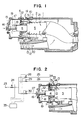
- the combustor comprises an outer cylinder 1, an inner cylinder (or combustion cylinder) 2 mounted within the outer cylinder 1, a tail cylinder 3 mounted within the outer cylinder 1 and connected at one end to the inner cylinder 2 and directed at the outer end toward a turbine, a premix chamber 4 provided at a head of the inner cylinder 2, a combustion chamber 5 for receiving a combustible fuel-air mixture, a premixture supply means provided at one side of the combustion chamber 5, an auxiliary burner 13 provided in the vicinity of the premixture supply means to be supplied with auxiliary fuel 12 and air, and an ignition plug 14 provided downstream of the auxiliary burner 13 to ignite the auxiliary burner 13.
- the premixture supply means comprises a first (inner) premixture supply means operable during a high-load operation of the combustor, and a second (outer) premixture supply means operable during a low-load operation of the combustor.
- the first premixture supply means includes a fuel nozzle 16 which is fixedly mounted on an end plate 15 fixedly mounted to one end of the outer cylinder 1 opposite to the turbine to supply fuel for a first premixture to the premix chamber 4.
- Fuel 18 is supplied to the premix chamber 4 from the fuel nozzle 16, and air 19 is supplied to the premix chamber 4 through a space between the fuel nozzle 16 and the inner peripheral surface of the inner cylinder 2.
- the second premixture supply means includes a premix burner 8 provided adjacent to the outer periphery of the premix chamber 4, that is, adjacent to the inner peripheral surface of the inner cylinder 2.
- the premix burner 8 is supplied with fuel 6 and air 7 so as to supply a second fuel-air premixture to the combustion chamber 5.
- the premix burner 8 includes a fuel chamber 32 provided in a flange 31 fixedly mounted on the outer cylinder 1, an annular flow passage 33, and fuel nozzles 34 projecting into the annular flow passage 33.
- the auxiliary burner 13 is disposed around the outer periphery of the premix burner 8 in the vicinity of an injection port of the premix burner 8, and is disposed adjacent to an abruptly-expanded portion 9 of the combustion chamber 5.
- Arrow 20 denotes the flow of air supplied from a compressor (not shown) to the combustor.
- a fuel supply system for supplying fuel to the combustor is shown in Fig. 2.
- This fuel supply system comprises a fuel pressure control valve 24 for controlling the flow rate of fuel 23 fed from a fuel source (not shown), three fuel supply pipes 25, 26 and 27 provided downstream of the control valve 24 in a branched manner to pass the auxiliary fuel 12, the first premixture fuel 18 and the second premixture fuel 6 therethrough, respectively, three fuel flow rate control valves 28, 29 and 30 mounted respectively on the three fuel supply pipes 25, 26 and 27 to control the flow rates of the respective fuels through these three fuel supply pipes, respectively, and a control 35 for producing control signals in accordance with the load level of the turbine to control the above valves 24, 28, 29 and 30.
- the auxiliary fuel 12 and the second premixture fuel 6 pass through the flange 31, and the auxiliary fuel 12 is supplied to the auxiliary burner 13 disposed adjacent to the abruptly-expanded portion 9 of the combustion chamber 5 while the second premixture fuel 6 reaches the fuel nozzles 34 via the fuel chamber 32 and is injected into the premix burner 8 from injection ports provided respectively at distal ends of these nozzles.
- the first premixture fuel 18 is supplied to the fuel nozzle 16 via the flow rate control valve 30. These fuels are not always supplied, but are supplied in the following manner.
- the ignition plug 14 is operated, and at the same time the flow control valve 28 is operated to allow the auxiliary fuel 12 to inject from the auxiliary burner 13 to form a flame at a recess portion 11.
- the flow rate control valve 29 is operated to flow a predetermined amount of the second premixture fuel 6 to form the second premixture, that is, a combustible fuel-air mixture, and this premixture is injected from the premix burner 8. This combustible mixture is burned by a heat source of the flame formed by the auxiliary burner 13.
- the flow control valve 30 is operated to feed the first premixture fuel 18 via the fuel nozzle 16 to the premix chamber 4 provided at the head of the combustor, thereby forming the first premixture, that is, a combustible fuel-air mixture, and this combustible mixture is supplied to the combustion chamber 5.
- These operation controls are automatically carried out by the signals from the control 35 in accordance with the load level of the turbine.
- Fig. 3 shows one example of a fuel control operation method within an operating range of the gas turbine.
- Fig. 3 shows the flow rate of the fuel 12 for the auxiliary burner 13, the flow rate of the second premixture fuel 6 for the premix burner 8 and the flow rate of the first premixture fuel 18 for the premix chamber 4 with respect to the turbine load.
- Fig. 3 shows the flow rate of the fuel 12 for the auxiliary burner 13, the flow rate of the second premixture fuel 6 for the premix burner 8 and the flow rate of the first premixture fuel 18 for the premix chamber 4 with respect to the turbine load.
- a solid line represents the flow rate of the total fuel introduced into the combustion chamber 5 in accordance with the turbine load
- a chain line represents the flow rate of the auxiliary fuel 12 fed to the auxiliary burner 13
- a one-dot chain line represents the flow rate of the second premixture fuel 6 fed to the premix burner 8
- a two-dot chain line represents the flow rate of the first premixture fuel 18 fed to the premix chamber 4.
- the second premixture fuel 6 is supplied to the premix burner 8 at the point a of the turbine no-load, and its flow rate increases, and then decreases in a stepwise manner at 25% of the full turbine load, and then increases at a rate half of the flow rate of the total fuel in accordance with the turbine load.
- the first premixture fuel 18 is supplied in a stepwise manner to the premix chamber 4 provided at the head of the inner cylinder 2 at 25% of the full turbine load, and its flow rate increases at a rate half of the flow rate of the total fuel in accordance with the turbine load.
- the flow rate of the first premixture fuel, as well as the flow rate of second premixture fuel amounts to 25% to 50% of the total fuel in the range of 25% to 100% of the full turbine load.
- Fig. 4 Patterns of flames formed in the combustion chamber 5 by the above fuel control are shown in Fig. 4.
- the auxiliary burner 13 is operated for a time period from the ignition of the auxiliary fuel 12 to the turbine no-load to form a flame 101 in the combustion chamber 5.
- the premix burner 8 forms a premix flame 102 in the combustion chamber 5 in the range from around the point a of the turbine no-load to 100% of the full turbine load, and solely effects combustion in the range from the turbine no-load to 25% of the full turbine load.
- the premixture fuel 18, supplied to the premix chamber 4 at the head of the inner cylinder 2, forms a combustion flame 103 in the range of 25% to 100% of the full turbine load. Namely, each of the first and second premixture fuels is supplied at a rate of 50% of the total fuel in the rated range in accordance with the turbine load.
- the fuel control operation method may be carried out in the following manner.
- fuel is supplied to the auxiliary burner throughout the entire turbine load to enhance flame stabilization at the outer periphery side of the combustion chamber, and at the same time the combustible mixtures from the premix burner and the premix chamber are burned in a more lean condition, thereby reducing NOx.
- the combustible mixtures from the premix burner and the premix chamber can be burned in a more lean condition, using the flame of the auxiliary burner as a basis.
- the transfer of flame from the auxiliary burner, as well as a combustion pattern of the combustible mixture fed from the premix chamber can be freely determined, thereby achieving a stable premix combustion and a very advantageous operation control.
- the auxiliary burner is used, and although this auxiliary burner is advantageous in achieving a smooth start of combustion and the stabilization of flame, the auxiliary burner is not always essential.
- similar effects can be achieved by providing an ignition plug on the premix burner disposed at the outer periphery side of the combustion chamber and by effecting a fuel-air ratio control so as to operate this premix burner for a period of time from the start of the combustion to a low-load state.
- Figs. 5 and 6 show combustion conditions (i.e., gas temperature, NOx concentration and CO concentration) within thecombustion chambers in the prior art and the present invention, respectively.
- Fig. 5 shows the condition of the upstream side of the combustion chamber during the diffusion-premix combustion.
- the gas temperature is high at the radially-central portion of the combustion chamber, and a low temperature region is formed at the outer peripheral portion of the combustion chamber. Therefore, the premix mixture flowing at the outer peripheral portion of the combustion chamber is not burned satisfactorily, thereby producing unburned substances such as CO.
- a cooling air layer is present about the wall surface of the combustion chamber, it is considerably difficult to remove such unburned substances once they are produced.
- the high temperature region at the radially- central portion of the combustion chamber constitutes a source of production of NOx, thus failing to achieve a great reduction of NOx.
- the first and second premixture supply means are provided inside and outside the combustion chamber, respectively.
- the outside second premixture supply means is operated during the low-load operation of the turbine, thus providing a complete premix construction, and as shown in Fig. 6, the gas temperature is relatively averaged to thereby reduce NOx and CO at the same time.
- the present invention since the flow or movement of air, etc., on the outer peripheral portion of the combustion chamber at its upstream side portion is relatively small, the flame from the auxiliary burner can be relatively easily formed, and also an excessive cooling at the outside of the combustion chamber is prevented during the low-load operation of the turbine, thereby adequately preventing the production of unburned substances. Further, for increasing the combustion in accordance with the turbine load, since the surrounding heat sources (contact ratio, etc.) are large, the thermal diffusion movement (flame propagation and combustibility) at the downstream side of the combustion chamber is rapid. This enables suppressing the production of unburned substances at those portions of the combustion chamber where the mixture is more lean and also at the outlet side of the combustion chamber. Therefore, the present invention provides an improved combustor which can suppress the production of NOx and CO over a range from the turbine no-load to the rated load.
- Fig. 7 shows a comparison in NOx characteristics in combustion between the prior art and the present invention. Even in the prior art, a region of low production of NOx exists in a certain range where the ratio of premix combustion amount to the diffusion combustion amount has a specified value. In the complete premix combustion according to the present invention, an amount of NOx can be reduced to less than 1/2 of that achieved by the prior art. Further, as shown in Fig. 8, in the combustor of the present invention, even when the fuel-air ratio is shifted 30% toward the lean side with respect to the prior art, there can be achieved a stable combustion free from the production of CO and other substances.
- Figs. 9 to 14 show various modified auxiliary burners.
- a plurality of holes or slits 41 are formed through an inner wall of a fuel tank 40 adjacent to a distal end thereof, the fuel tank 40 receiving the auxiliary fuel 12.
- a recess portion 11 is provided immediately adjacent to the distal end of the fuel tank 40, and is defined by an abruptly-expanded portion 9 and an annular portion 10.
- FIG. 11 shows a modification in which holes 45 are formed through a wall of the premix burner 8 adjacent to a proximal end of a fuel tank 40, so that the auxiliary fuel 12 can be injected into the premix burner 8.
- Fig. 12 shows another modification in which holes 46 is formed through the abruptly-expanded portion 9 of the recess portion 11. As shown in Figs. 11 and 12, a constricted portion 47 or 48 is formed at the outlet of the premix chamber 4 provided at the upstream side of the combustion chamber 5 at its radially-central portion.
- Fig. 10 shows a premix-and-auxiliary burner 43 which mixes air 44 and the fuel 12 together so as to form a flame 101 in the combustion chamber 5.
- the premix burner 8a may be inclined at an angle 49 relative to the premix chamber 4 as shown in Fig. 13, or the premix burner 8b may be disposed perpendicular to the premix chamber 4 as indicated by reference numeral 50 in Fig. 14. With this arrangement, the combustible fuel-air mixture from the premix chamber 4 can be effectively burned.
- the premix burner provided at one end (head side) of the combustion cylinder is disposed generally concentric with the combustion cylinder.
- the first premix burner is operable in a high-load range of the combustor.
- the second premix burner is provided adjacent to the outer periphery of the first premix burner, and is operable at least a low-load range of the combustor.
- the combustible fuel-air mixture is supplied to the combustion chamber from the upstream side of the combustion chamber at its radially-central portion, and therefore the surrounding heat source is large when the combustible mixture is burned, so that the thermal diffusion movement is rapid at the downstream side, thereby effectively suppressing the development of the unburned substance at the outlet of the combustion chamber.
Landscapes
- Engineering & Computer Science (AREA)
- Chemical & Material Sciences (AREA)
- Combustion & Propulsion (AREA)
- Mechanical Engineering (AREA)
- General Engineering & Computer Science (AREA)
Abstract
Description
- This invention relates generally to a combustor for use, for example, in a gas turbine, and more particularly to a combustor of the premix combustion-type and also to a method of operating such a combustor.
- Most of conventional combustors of the general type employ a two-stage combustion system to reduce production of NOx. More specifically, in such a combustor, a diffusion combustion is effected at one end of a combustion cylinder, at the head of the combustor, for the purpose of stabilizing a flame, whereas a premix combustion highly effective in reducing NOx is effected downstream of the one end of the combustion cylinder.
- Such a combustor is disclosed, for example, in U. S. Patent No. 4,292,801. More specifically, this conventional combustor comprises a first-stage diffusion combustion burner mounted on a head of the combustor, and a second-stage diffusion combustion burner extending from the combustor head toward a central portion of a combustion chamber. The diameter of the combustion chamber is reduced or constricted in the vicinity of an outlet of the second-stage burner. At the start of combustion, fuel is supplied to the first-stage burner and is ignited so as to effect a diffusion combustion in a first-stage combustion chamber. Then, as the combustion load increases, fuel is introduced into the second-stage burner so as to effect a diffusion combustion in a second-stage combustion chamber. Then, simultaneously when the first-stage fuel is transferred to the second-stage burner, the first-stage burner is extinguished (turned off), and then fuel is again charged into the first-stage burner. At this time, the first-stage combustion chamber serves as a premix chamber for mixing the fuel and the air together. Therefore, at the time of a high-load combustion, a fuel-air premixture from the first-stage combustion chamber is burned by the heat source of the second-stage burner so as to continue the combustion.
- In the combustor of such a construction, premix combustion is carried out mainly when the combustor is operated under a load higher than a predetermined level, and therefore this combustor is very effective in reducing NOx. This type of combustor is satisfactory in that during a high-load operation, it exhausts small amounts of NOx and unburned substances such as CO, which means that the combustion is sufficiently effected in the combustion chamber, and therefore the combustible fuel-air mixture is hardly discharged in an unburned condition from the combustor. However, during a low-load operation of the combustor, that is, under a condition in which the fuel-air mixture is lean, the cooling air enters about the wall surface of the combustion chamber, so that the amount of discharge of unburned substances such as CO tends to increase.
- It is an object of this invention to solve the above problems of the prior art.
- Another object of the invention is to provide a combustor which will not exhaust CO and other substances even under a low-load operation of the combustor, that is, when a combustible fuel-air mixture is lean.
- To the above-described end, the present invention provides a combustor comprising premixture supply means which comprises first premixture supply means disposed about a central portion of a combustion chamber generally coaxial with a combustion cylinder and operable when the combustor is under a high load, and second premixture supply means provided adjacent to an outer periphery of the first premixture supply means and operable when the combustor is under a low load.
- In one aspect, the present invention provides a method of operating a combustor comprising a combustion cylinder having a combustion chamber therein, and premixture supply means provided at one end of the combustion cylinder to supply a combustible mixture to the combustion chamber, the premixture supply means including at least two inner and outer premixture supply means, the outer premixture supply means being operable in a low-load range of the combustor whereas the inner and outer premixture supply means are operable in a high-load range of the combustor at above a predetermined load, the first and second premixture supply means including first and second burners, respectively, the method comprising the step of:
operating the first and second burners in such a manner that the ratio of the load borne by the first burner to the load borne by the second burner is 1:1 in the high-load range. - With such arrangement of the invention, the burner of the second premixture supply means, that is, the burner disposed near the outer periphery of the combustion chamber is operated to enable maintaining the temperature of combustion gas high at the outer periphery of the combustion chamber even in a low load condition of the combustor, so that in a low load condition of the combustor, unburned substances such as CO tending to be produced at the outer periphery of the combustion chamber can be prevented from being produced.
-
- Fig. 1 is a vertical cross-sectional view of a combustor in accordance with the present invention;
- Fig. 2 is a cross-sectional view of an essential portion of the combustor of Fig. 1, showing a fuel supply system;
- Fig. 3 is a graph representative of the relationship of fuel flow rates and operating burners with respect to a turbine load;
- Fig. 4 is a schematic view of the combustor, showing patterns of flames formed by burners;
- Fig. 5 is a graph showing gas temperature and NOx concentration and CO concentration in a combustor of the prior art;
- Fig. 6 is a graph showing gas temperature and NOx concentration and CO concentration in the combustor of the present invention;
- Fig. 7 is a graph showing the relation between the fuel ratio and the NOx exhaust concentration in the present invention and the prior art;
- Fig. 8 is a graph showing the stability with respect to the fuel-air ratio; and
- Figs. 9 to 14 are fragmentary, vertical cross-sectional views, showing modified auxiliary burners of the invention.
- Fig. 1 shows one preferred embodiment of a combustor of the present invention. The combustor comprises an
outer cylinder 1, an inner cylinder (or combustion cylinder) 2 mounted within theouter cylinder 1, atail cylinder 3 mounted within theouter cylinder 1 and connected at one end to theinner cylinder 2 and directed at the outer end toward a turbine, apremix chamber 4 provided at a head of theinner cylinder 2, acombustion chamber 5 for receiving a combustible fuel-air mixture, a premixture supply means provided at one side of thecombustion chamber 5, anauxiliary burner 13 provided in the vicinity of the premixture supply means to be supplied withauxiliary fuel 12 and air, and anignition plug 14 provided downstream of theauxiliary burner 13 to ignite theauxiliary burner 13. The premixture supply means comprises a first (inner) premixture supply means operable during a high-load operation of the combustor, and a second (outer) premixture supply means operable during a low-load operation of the combustor. The first premixture supply means includes afuel nozzle 16 which is fixedly mounted on anend plate 15 fixedly mounted to one end of theouter cylinder 1 opposite to the turbine to supply fuel for a first premixture to thepremix chamber 4.Fuel 18 is supplied to thepremix chamber 4 from thefuel nozzle 16, andair 19 is supplied to thepremix chamber 4 through a space between thefuel nozzle 16 and the inner peripheral surface of theinner cylinder 2. Therefore, the first premixture is formed by thefuel 18 and theair 19 within thepremix chamber 4, and this combustible fuel-air mixture is supplied to thecombustion chamber 5. The second premixture supply means includes apremix burner 8 provided adjacent to the outer periphery of thepremix chamber 4, that is, adjacent to the inner peripheral surface of theinner cylinder 2. Thepremix burner 8 is supplied withfuel 6 and air 7 so as to supply a second fuel-air premixture to thecombustion chamber 5. As shown in Fig. 2, thepremix burner 8 includes afuel chamber 32 provided in a flange 31 fixedly mounted on theouter cylinder 1, an annular flow passage 33, and fuel nozzles 34 projecting into the annular flow passage 33. Theauxiliary burner 13 is disposed around the outer periphery of thepremix burner 8 in the vicinity of an injection port of thepremix burner 8, and is disposed adjacent to an abruptly-expandedportion 9 of thecombustion chamber 5.Arrow 20 denotes the flow of air supplied from a compressor (not shown) to the combustor. - A fuel supply system for supplying fuel to the combustor is shown in Fig. 2. This fuel supply system comprises a fuel
pressure control valve 24 for controlling the flow rate offuel 23 fed from a fuel source (not shown), threefuel supply pipes control valve 24 in a branched manner to pass theauxiliary fuel 12, thefirst premixture fuel 18 and thesecond premixture fuel 6 therethrough, respectively, three fuel flowrate control valves fuel supply pipes control 35 for producing control signals in accordance with the load level of the turbine to control theabove valves - The operation of the above combustor as well as a method of operating the combustor will now be described with reference to Figs. 1 and 2.
- The
fuel 23 from the fuel source, after passing past the fuelpressure control valve 24, is divided into theauxiliary fuel 12, thefirst premixture fuel 18 and thesecond premixture fuel 6. These fuels are supplied to theauxiliary burner 13 and the first and second premixture supply means, respectively, via the respective fuel flowrate control valves fuel supply pipes auxiliary fuel 12 and thesecond premixture fuel 6 pass through the flange 31, and theauxiliary fuel 12 is supplied to theauxiliary burner 13 disposed adjacent to the abruptly-expandedportion 9 of thecombustion chamber 5 while thesecond premixture fuel 6 reaches the fuel nozzles 34 via thefuel chamber 32 and is injected into thepremix burner 8 from injection ports provided respectively at distal ends of these nozzles. Thefirst premixture fuel 18 is supplied to thefuel nozzle 16 via the flowrate control valve 30. These fuels are not always supplied, but are supplied in the following manner. At the start of combustion, theignition plug 14 is operated, and at the same time theflow control valve 28 is operated to allow theauxiliary fuel 12 to inject from theauxiliary burner 13 to form a flame at a recess portion 11. Then, the flowrate control valve 29 is operated to flow a predetermined amount of thesecond premixture fuel 6 to form the second premixture, that is, a combustible fuel-air mixture, and this premixture is injected from thepremix burner 8. This combustible mixture is burned by a heat source of the flame formed by theauxiliary burner 13. Further, at the time of a high-load combustion, theflow control valve 30 is operated to feed thefirst premixture fuel 18 via thefuel nozzle 16 to thepremix chamber 4 provided at the head of the combustor, thereby forming the first premixture, that is, a combustible fuel-air mixture, and this combustible mixture is supplied to thecombustion chamber 5. These operation controls are automatically carried out by the signals from thecontrol 35 in accordance with the load level of the turbine. - Fig. 3 shows one example of a fuel control operation method within an operating range of the gas turbine. Fig. 3 shows the flow rate of the
fuel 12 for theauxiliary burner 13, the flow rate of thesecond premixture fuel 6 for thepremix burner 8 and the flow rate of thefirst premixture fuel 18 for thepremix chamber 4 with respect to the turbine load. In Fig. 3, a solid line represents the flow rate of the total fuel introduced into thecombustion chamber 5 in accordance with the turbine load, a chain line represents the flow rate of theauxiliary fuel 12 fed to theauxiliary burner 13, and a one-dot chain line represents the flow rate of thesecond premixture fuel 6 fed to thepremix burner 8, and a two-dot chain line represents the flow rate of thefirst premixture fuel 18 fed to thepremix chamber 4. As is clear from Fig. 3, the flow rate of theauxiliary fuel 12 increases from the start of combustion, and decreases in a stepwise manner about a point a of the turbine no-load, without changing the load level, and then gradually decreases to the turbine no-load. Thesecond premixture fuel 6 is supplied to thepremix burner 8 at the point a of the turbine no-load, and its flow rate increases, and then decreases in a stepwise manner at 25% of the full turbine load, and then increases at a rate half of the flow rate of the total fuel in accordance with the turbine load. Thefirst premixture fuel 18 is supplied in a stepwise manner to thepremix chamber 4 provided at the head of theinner cylinder 2 at 25% of the full turbine load, and its flow rate increases at a rate half of the flow rate of the total fuel in accordance with the turbine load. Therefore, the flow rate of the first premixture fuel, as well as the flow rate of second premixture fuel, amounts to 25% to 50% of the total fuel in the range of 25% to 100% of the full turbine load. Patterns of flames formed in thecombustion chamber 5 by the above fuel control are shown in Fig. 4. At the start of combustion, theauxiliary burner 13 is operated for a time period from the ignition of theauxiliary fuel 12 to the turbine no-load to form aflame 101 in thecombustion chamber 5. Thepremix burner 8 forms apremix flame 102 in thecombustion chamber 5 in the range from around the point a of the turbine no-load to 100% of the full turbine load, and solely effects combustion in the range from the turbine no-load to 25% of the full turbine load. Thepremixture fuel 18, supplied to thepremix chamber 4 at the head of theinner cylinder 2, forms acombustion flame 103 in the range of 25% to 100% of the full turbine load. Namely, each of the first and second premixture fuels is supplied at a rate of 50% of the total fuel in the rated range in accordance with the turbine load. - The fuel control operation method may be carried out in the following manner. In order to achieve a great reduction of NOx by the premix combustion, fuel is supplied to the auxiliary burner throughout the entire turbine load to enhance flame stabilization at the outer periphery side of the combustion chamber, and at the same time the combustible mixtures from the premix burner and the premix chamber are burned in a more lean condition, thereby reducing NOx. Further, in the case where a fuel-air ratio control function is applied to the premix burner, the combustible mixtures from the premix burner and the premix chamber can be burned in a more lean condition, using the flame of the auxiliary burner as a basis. Particularly where the premix burner is subjected to a fuel-air ratio control, the transfer of flame from the auxiliary burner, as well as a combustion pattern of the combustible mixture fed from the premix chamber, can be freely determined, thereby achieving a stable premix combustion and a very advantageous operation control. In the above examples, the auxiliary burner is used, and although this auxiliary burner is advantageous in achieving a smooth start of combustion and the stabilization of flame, the auxiliary burner is not always essential. For example, similar effects can be achieved by providing an ignition plug on the premix burner disposed at the outer periphery side of the combustion chamber and by effecting a fuel-air ratio control so as to operate this premix burner for a period of time from the start of the combustion to a low-load state.
- Figs. 5 and 6 show combustion conditions (i.e., gas temperature, NOx concentration and CO concentration) within thecombustion chambers in the prior art and the present invention, respectively. Fig. 5 shows the condition of the upstream side of the combustion chamber during the diffusion-premix combustion. The gas temperature is high at the radially-central portion of the combustion chamber, and a low temperature region is formed at the outer peripheral portion of the combustion chamber. Therefore, the premix mixture flowing at the outer peripheral portion of the combustion chamber is not burned satisfactorily, thereby producing unburned substances such as CO. Particularly, since a cooling air layer is present about the wall surface of the combustion chamber, it is considerably difficult to remove such unburned substances once they are produced. Further, the high temperature region at the radially- central portion of the combustion chamber constitutes a source of production of NOx, thus failing to achieve a great reduction of NOx. On the other hand, according to the present invention, the first and second premixture supply means are provided inside and outside the combustion chamber, respectively. The outside second premixture supply means is operated during the low-load operation of the turbine, thus providing a complete premix construction, and as shown in Fig. 6, the gas temperature is relatively averaged to thereby reduce NOx and CO at the same time. In other words, in the present invention, since the flow or movement of air, etc., on the outer peripheral portion of the combustion chamber at its upstream side portion is relatively small, the flame from the auxiliary burner can be relatively easily formed, and also an excessive cooling at the outside of the combustion chamber is prevented during the low-load operation of the turbine, thereby adequately preventing the production of unburned substances. Further, for increasing the combustion in accordance with the turbine load, since the surrounding heat sources (contact ratio, etc.) are large, the thermal diffusion movement (flame propagation and combustibility) at the downstream side of the combustion chamber is rapid. This enables suppressing the production of unburned substances at those portions of the combustion chamber where the mixture is more lean and also at the outlet side of the combustion chamber. Therefore, the present invention provides an improved combustor which can suppress the production of NOx and CO over a range from the turbine no-load to the rated load.
- Fig. 7 shows a comparison in NOx characteristics in combustion between the prior art and the present invention. Even in the prior art, a region of low production of NOx exists in a certain range where the ratio of premix combustion amount to the diffusion combustion amount has a specified value. In the complete premix combustion according to the present invention, an amount of NOx can be reduced to less than 1/2 of that achieved by the prior art. Further, as shown in Fig. 8, in the combustor of the present invention, even when the fuel-air ratio is shifted 30% toward the lean side with respect to the prior art, there can be achieved a stable combustion free from the production of CO and other substances.
- Figs. 9 to 14 show various modified auxiliary burners. In an
auxiliary burner 13a shown in Fig. 9, a plurality of holes or slits 41 are formed through an inner wall of afuel tank 40 adjacent to a distal end thereof, thefuel tank 40 receiving theauxiliary fuel 12. A recess portion 11 is provided immediately adjacent to the distal end of thefuel tank 40, and is defined by an abruptly-expandedportion 9 and anannular portion 10. When theauxiliary burner 13a is to be ignited, theauxiliary fuel 12 is injected through theholes 41 toward the air 7 fed from thepremix burner 8, and this fuel-air mixture is ignited by an ignition plug to form aflame 101. Thisflame 101 is kept stable byvortexes 42 induced in the recess portion 11 by a jet of the air 7. Fig. 11 shows a modification in which holes 45 are formed through a wall of thepremix burner 8 adjacent to a proximal end of afuel tank 40, so that theauxiliary fuel 12 can be injected into thepremix burner 8. Fig. 12 shows another modification in which holes 46 is formed through the abruptly-expandedportion 9 of the recess portion 11. As shown in Figs. 11 and 12, aconstricted portion premix chamber 4 provided at the upstream side of thecombustion chamber 5 at its radially-central portion. With this construction, the velocity of flow of the combustible fuel-air mixture is increased, thereby effectively preventing the flame from being directed reversely. Fig. 10 shows a premix-and-auxiliary burner 43 which mixesair 44 and thefuel 12 together so as to form aflame 101 in thecombustion chamber 5. In order to effectively transfer the flame of thepremix burner 8 to the combustible fuel-air mixture fed from thepremix chamber 4, thepremix burner 8a may be inclined at anangle 49 relative to thepremix chamber 4 as shown in Fig. 13, or the premix burner 8b may be disposed perpendicular to thepremix chamber 4 as indicated byreference numeral 50 in Fig. 14. With this arrangement, the combustible fuel-air mixture from thepremix chamber 4 can be effectively burned. - As described above, in the present invention, the premix burner provided at one end (head side) of the combustion cylinder is disposed generally concentric with the combustion cylinder. The first premix burner is operable in a high-load range of the combustor. The second premix burner is provided adjacent to the outer periphery of the first premix burner, and is operable at least a low-load range of the combustor. With this construction, even when the combustor is under a low load, an unburned substance (i.e., CO), which would tend to develop adjacent to the inner peripheral surface of the combustion cylinder, that is, at the outer peripheral portion of the combustion chamber, can be sufficiently prevented from being produced.
- Further, as the load increases, the combustible fuel-air mixture is supplied to the combustion chamber from the upstream side of the combustion chamber at its radially-central portion, and therefore the surrounding heat source is large when the combustible mixture is burned, so that the thermal diffusion movement is rapid at the downstream side, thereby effectively suppressing the development of the unburned substance at the outlet of the combustion chamber.
- Although the present invention has been specifically described with reference to the above embodiments, the invention itself is not to be restricted to such embodiments, and various modifications can be made without departing from the scope of appended claims.
Claims (10)
the improvement wherein said premixture supply means comprises outer premixture supply means (8,32) provided in the vicinity of an inner wall surface of said combustion cylinder (2) and operable when said combustor is under a low load, and inner premixture supply means (4,16) provided inwardly of said outer premixture supply means (8,32) and near the axis of said combustion cylinder (2) and operable when said combustor is under a high load; and
there is provided an auxiliary burner (13) operable at the start of the operation of said combustor and having an ignition plug (14) provided in the vicinity of said outer premixture supply means (8,32).
the improvement wherein said premixture supply means comprises first premixture supply means (4,16) disposed in a central portion of said combustion chamber (5) disposed generally concentric with said combustion cylinder (2) and operable when said combustor is under a high load, and second premixture supply means (8,32) provided adjacent to an outer periphery of said first premixture supply means (4,16) and operable when said combustor is under a low load.
the improvement wherein said premixture supply means comprises first premixture supply means (4,16) disposed along the axis of said combustion cylinder (2) and operable when said combustor is under a high load, and second premixture supply means (8,32) provided adjacent to an outer periphery of said first premixture supply means (4,16) and operable over an entire load range of said combustor.
the improvement wherein said premixture supply means comprises first premixture supply means (4,16) disposed along the axis of said combustion cylinder (2) and operable in a high-load range of said combustor, and second premixture supply means (8,32) provided adjacent to an outer periphery of said first premixture supply means (4,16) and operable at least in a low-load range of said combustor.
the improvement wherein said premixture supply means comprises first premixture supply means (4,16) disposed along the axis of said combustion cylinder (2) and operable in a high-load range of said combustor, and second premixture supply means (8,32) provided adjacent to an outer periphery of said first premixture supply means (4,16) and operable over an entire load range of said combustor; and there is provided an auxiliary burner (13) adjacent to an outer periphery of said second premixture supply means (8,32) and adapted to be ignited and burned at the start of the operation of said combustor.
the improvement wherein said premixture supply means comprises first premixture supply means (4,16) disposed in a radially-central portion of said combustion cylinder (2) and operable in a high-load range of said combustor, second premixture supply means (8,32) provided adjacent to an outer periphery of said first premixture supply means (4,16) and operable over an entire load range of said combustor, and third premixture supply means (13) provided adjacent to an outer periphery of said second premixture supply means (8,32) and operable in a low-load range of said combustor.
the improvement wherein said premixture supply means comprises first premixture supply means (4,16) disposed in a radially-central portion of said combustion cylinder (2) and operable in a high-load range of said combustor, and second premixture supply means (8,32) provided adjacent to an outer periphery of said first premixture supply means (4,16) and operable over an entire load range of said combustor; and there is provided an auxiliary burner (13) in the vicinity of said second premixture supply means (8,32) and adapted to ignite said second premixture supply means (8,32).
the improvement wherein said premixture supply means comprises at least two inner and outer premixture supply means (4,16;8,32) said outer premixture supply means (8,32) being operable when said combustor is under a low load, and said inner and outer premixture supply means (4,16;8,32) being operable at above a predetermined load level of said combustor.
a combustion cylinder (2) having a combustion chamber (5) therein;
first premixture supply means (4,16) provided on one side of said combustion cylinder (2) and disposed along the axis of said combustion cylinder (2) so as to supply a combustible mixture to said combustion chamber (5), said first premixture supply means (4,16) including a burner;
a second premixture supply means (8,32) provided adjacent to an outer periphery of said first premixture supply means (4,16) and adapted to supply a combustible mixture to said combustion chamber (5), said second premixture supply means (8,32) including a burner (8); and
a burner (13) provided in the vicinity of said second premixture supply means (8,32) and adapted to ignite the combustible mixture fed from said second premixture supply means (8,32) and
wherein an amount of supply of the combustible mixture from said first and second premixture supply means (4,16;8,32) are controlled so that said burner (8) of said second premixture supply means can bear all the load of said combustor in a low-load range of said combustor, and said burners of said first and second premixture supply means (4,16;8,32) can bear all the load of said combustor in a high-load range of the combustor.
operating said first and second burners in such a manner that the ratio of the load borne by said first burner to the load borne by said second burner is 1:1 in said high-load range.
Applications Claiming Priority (2)
| Application Number | Priority Date | Filing Date | Title |
|---|---|---|---|
| JP128851/89 | 1989-05-24 | ||
| JP1128851A JPH0772616B2 (en) | 1989-05-24 | 1989-05-24 | Combustor and operating method thereof |
Publications (2)
| Publication Number | Publication Date |
|---|---|
| EP0399336A1 true EP0399336A1 (en) | 1990-11-28 |
| EP0399336B1 EP0399336B1 (en) | 1996-09-04 |
Family
ID=14994948
Family Applications (1)
| Application Number | Title | Priority Date | Filing Date |
|---|---|---|---|
| EP90109121A Expired - Lifetime EP0399336B1 (en) | 1989-05-24 | 1990-05-15 | Combustor and method of operating same |
Country Status (4)
| Country | Link |
|---|---|
| US (1) | US5201181A (en) |
| EP (1) | EP0399336B1 (en) |
| JP (1) | JPH0772616B2 (en) |
| DE (1) | DE69028348T2 (en) |
Cited By (8)
| Publication number | Priority date | Publication date | Assignee | Title |
|---|---|---|---|---|
| FR2727192A1 (en) * | 1994-11-23 | 1996-05-24 | Snecma | INJECTION SYSTEM FOR A TWO-HEAD COMBUSTION CHAMBER |
| EP0800041A2 (en) * | 1996-04-03 | 1997-10-08 | ROLLS-ROYCE plc | Gas turbine engine combustion equipment |
| EP0697507A3 (en) * | 1994-08-19 | 1998-09-30 | Asea Brown Boveri Ag | Gasturbine speed control method for sudden load loss |
| EP0898117A2 (en) * | 1997-08-22 | 1999-02-24 | Kabushiki Kaisha Toshiba | Dual fuel atomization with backflow prevention |
| EP0845634A3 (en) * | 1996-11-29 | 1999-04-28 | Kabushiki Kaisha Toshiba | Gas turbine combustor and operating method thereof |
| DE102006019722A1 (en) * | 2006-03-31 | 2007-10-04 | Alstom Technology Ltd. | Secondary burner attachment device for sequential operating gas turbine system, has fuel mixture burned in primary burner during formation of hot gases, supplied to burner for secondary successive combustion, formed as flow channel |
| EP1970629A1 (en) * | 2007-03-15 | 2008-09-17 | Siemens Aktiengesellschaft | Burner fuel staging |
| US7937950B2 (en) | 2006-03-31 | 2011-05-10 | Alstom Technology Ltd. | Device for fastening a sequentially operated burner in a gas turbine arrangement |
Families Citing this family (26)
| Publication number | Priority date | Publication date | Assignee | Title |
|---|---|---|---|---|
| JP3037804B2 (en) * | 1991-12-02 | 2000-05-08 | 株式会社日立製作所 | Control method and control device for gas turbine combustor |
| US5402634A (en) * | 1993-10-22 | 1995-04-04 | United Technologies Corporation | Fuel supply system for a staged combustor |
| GB9325708D0 (en) * | 1993-12-16 | 1994-02-16 | Rolls Royce Plc | A gas turbine engine combustion chamber |
| US5465570A (en) * | 1993-12-22 | 1995-11-14 | United Technologies Corporation | Fuel control system for a staged combustor |
| JP2950720B2 (en) * | 1994-02-24 | 1999-09-20 | 株式会社東芝 | Gas turbine combustion device and combustion control method therefor |
| US5415000A (en) * | 1994-06-13 | 1995-05-16 | Westinghouse Electric Corporation | Low NOx combustor retro-fit system for gas turbines |
| US5601238A (en) * | 1994-11-21 | 1997-02-11 | Solar Turbines Incorporated | Fuel injection nozzle |
| US5822992A (en) * | 1995-10-19 | 1998-10-20 | General Electric Company | Low emissions combustor premixer |
| DE19545311B4 (en) * | 1995-12-05 | 2006-09-14 | Alstom | Method for operating a combustion chamber equipped with premix burners |
| DE10000415A1 (en) * | 2000-01-07 | 2001-09-06 | Alstom Power Schweiz Ag Baden | Method and device for suppressing flow vortices within a fluid power machine |
| US6868676B1 (en) | 2002-12-20 | 2005-03-22 | General Electric Company | Turbine containing system and an injector therefor |
| JP3944609B2 (en) * | 2003-12-16 | 2007-07-11 | 川崎重工業株式会社 | Fuel nozzle |
| US20050227195A1 (en) * | 2004-04-08 | 2005-10-13 | George Kenneth R | Combustion burner assembly having low oxides of nitrogen emission |
| US7383684B2 (en) * | 2006-04-10 | 2008-06-10 | Deere & Company | Hybrid engine |
| US7891185B2 (en) * | 2007-08-17 | 2011-02-22 | Deere & Company | Turbo-generator control with variable valve actuation |
| JP2009156542A (en) * | 2007-12-27 | 2009-07-16 | Mitsubishi Heavy Ind Ltd | Burner for gas turbine |
| EP2107313A1 (en) * | 2008-04-01 | 2009-10-07 | Siemens Aktiengesellschaft | Fuel staging in a burner |
| US8220269B2 (en) * | 2008-09-30 | 2012-07-17 | Alstom Technology Ltd. | Combustor for a gas turbine engine with effusion cooled baffle |
| US8220271B2 (en) * | 2008-09-30 | 2012-07-17 | Alstom Technology Ltd. | Fuel lance for a gas turbine engine including outer helical grooves |
| FR2969703B1 (en) * | 2010-12-23 | 2014-11-28 | Snecma | FUEL SUPPLY METHOD OF A TURBOMACHINE |
| US8919132B2 (en) | 2011-05-18 | 2014-12-30 | Solar Turbines Inc. | Method of operating a gas turbine engine |
| US8893500B2 (en) | 2011-05-18 | 2014-11-25 | Solar Turbines Inc. | Lean direct fuel injector |
| US9182124B2 (en) | 2011-12-15 | 2015-11-10 | Solar Turbines Incorporated | Gas turbine and fuel injector for the same |
| EP3084307B1 (en) | 2013-12-19 | 2018-10-24 | United Technologies Corporation | Dilution passage arrangement for gas turbine engine combustor |
| US10704787B2 (en) * | 2016-03-30 | 2020-07-07 | General Electric Company | Closed trapped vortex cavity pilot for a gas turbine engine augmentor |
| US10222066B2 (en) * | 2016-05-26 | 2019-03-05 | Siemens Energy, Inc. | Ducting arrangement with injector assemblies arranged in an expanding cross-sectional area of a downstream combustion stage in a gas turbine engine |
Citations (7)
| Publication number | Priority date | Publication date | Assignee | Title |
|---|---|---|---|---|
| GB2013788A (en) * | 1978-01-28 | 1979-08-15 | Rolls Royce | Gas turbine engine combustion equipment |
| GB2072827A (en) * | 1980-03-29 | 1981-10-07 | Rolls Royce | A tubo-annular combustion chamber |
| GB2146425A (en) * | 1983-09-08 | 1985-04-17 | Hitachi Ltd | Method of supplying fuel into gas turbine combustor |
| EP0169431A1 (en) * | 1984-07-10 | 1986-01-29 | Hitachi, Ltd. | Gas turbine combustor |
| US4735052A (en) * | 1985-09-30 | 1988-04-05 | Kabushiki Kaisha Toshiba | Gas turbine apparatus |
| EP0269824A2 (en) * | 1986-11-25 | 1988-06-08 | General Electric Company | Premixed pilot nozzle for dry low NOx combustor |
| EP0281961A1 (en) * | 1987-03-06 | 1988-09-14 | Hitachi, Ltd. | Gas turbine combustor and combustion method therefor |
Family Cites Families (2)
| Publication number | Priority date | Publication date | Assignee | Title |
|---|---|---|---|---|
| US4249373A (en) * | 1978-01-28 | 1981-02-10 | Rolls-Royce Ltd. | Gas turbine engine |
| JPS6149136A (en) * | 1984-08-16 | 1986-03-11 | Mitsubishi Heavy Ind Ltd | Operation control method of gas turbine |
-
1989
- 1989-05-24 JP JP1128851A patent/JPH0772616B2/en not_active Expired - Fee Related
-
1990
- 1990-05-14 US US07/523,347 patent/US5201181A/en not_active Expired - Fee Related
- 1990-05-15 DE DE69028348T patent/DE69028348T2/en not_active Expired - Fee Related
- 1990-05-15 EP EP90109121A patent/EP0399336B1/en not_active Expired - Lifetime
Patent Citations (7)
| Publication number | Priority date | Publication date | Assignee | Title |
|---|---|---|---|---|
| GB2013788A (en) * | 1978-01-28 | 1979-08-15 | Rolls Royce | Gas turbine engine combustion equipment |
| GB2072827A (en) * | 1980-03-29 | 1981-10-07 | Rolls Royce | A tubo-annular combustion chamber |
| GB2146425A (en) * | 1983-09-08 | 1985-04-17 | Hitachi Ltd | Method of supplying fuel into gas turbine combustor |
| EP0169431A1 (en) * | 1984-07-10 | 1986-01-29 | Hitachi, Ltd. | Gas turbine combustor |
| US4735052A (en) * | 1985-09-30 | 1988-04-05 | Kabushiki Kaisha Toshiba | Gas turbine apparatus |
| EP0269824A2 (en) * | 1986-11-25 | 1988-06-08 | General Electric Company | Premixed pilot nozzle for dry low NOx combustor |
| EP0281961A1 (en) * | 1987-03-06 | 1988-09-14 | Hitachi, Ltd. | Gas turbine combustor and combustion method therefor |
Cited By (16)
| Publication number | Priority date | Publication date | Assignee | Title |
|---|---|---|---|---|
| EP0697507A3 (en) * | 1994-08-19 | 1998-09-30 | Asea Brown Boveri Ag | Gasturbine speed control method for sudden load loss |
| EP0718559A1 (en) * | 1994-11-23 | 1996-06-26 | Societe Nationale D'etude Et De Construction De Moteurs D'aviation "Snecma" | Fuel distribution system for the injection heads of a double annular combustor |
| US5634328A (en) * | 1994-11-23 | 1997-06-03 | Societe Nationale D'etude Et De Construction De Moteurs D'aviation S.N.E.C.M.A. | Method of supplying fuel to a dual head combustion chamber |
| FR2727192A1 (en) * | 1994-11-23 | 1996-05-24 | Snecma | INJECTION SYSTEM FOR A TWO-HEAD COMBUSTION CHAMBER |
| EP0800041A3 (en) * | 1996-04-03 | 2000-06-14 | ROLLS-ROYCE plc | Gas turbine engine combustion equipment |
| EP0800041A2 (en) * | 1996-04-03 | 1997-10-08 | ROLLS-ROYCE plc | Gas turbine engine combustion equipment |
| EP0845634A3 (en) * | 1996-11-29 | 1999-04-28 | Kabushiki Kaisha Toshiba | Gas turbine combustor and operating method thereof |
| EP0898117A3 (en) * | 1997-08-22 | 2000-06-28 | Kabushiki Kaisha Toshiba | Dual fuel atomization with backflow prevention |
| EP0898117A2 (en) * | 1997-08-22 | 1999-02-24 | Kabushiki Kaisha Toshiba | Dual fuel atomization with backflow prevention |
| US6199368B1 (en) | 1997-08-22 | 2001-03-13 | Kabushiki Kaisha Toshiba | Coal gasification combined cycle power generation plant and an operating method thereof |
| CN100380046C (en) * | 1997-08-22 | 2008-04-09 | 东芝株式会社 | Gasifying combined generating apparatus and operation method therefor |
| DE102006019722A1 (en) * | 2006-03-31 | 2007-10-04 | Alstom Technology Ltd. | Secondary burner attachment device for sequential operating gas turbine system, has fuel mixture burned in primary burner during formation of hot gases, supplied to burner for secondary successive combustion, formed as flow channel |
| US7937950B2 (en) | 2006-03-31 | 2011-05-10 | Alstom Technology Ltd. | Device for fastening a sequentially operated burner in a gas turbine arrangement |
| EP1970629A1 (en) * | 2007-03-15 | 2008-09-17 | Siemens Aktiengesellschaft | Burner fuel staging |
| WO2008110554A1 (en) * | 2007-03-15 | 2008-09-18 | Siemens Aktiengesellschaft | Burner fuel staging |
| US8484979B2 (en) | 2007-03-15 | 2013-07-16 | Siemens Aktiengesellschaft | Burner fuel staging |
Also Published As
| Publication number | Publication date |
|---|---|
| EP0399336B1 (en) | 1996-09-04 |
| US5201181A (en) | 1993-04-13 |
| JPH0772616B2 (en) | 1995-08-02 |
| DE69028348D1 (en) | 1996-10-10 |
| JPH02309124A (en) | 1990-12-25 |
| DE69028348T2 (en) | 1997-01-16 |
Similar Documents
| Publication | Publication Date | Title |
|---|---|---|
| US5201181A (en) | Combustor and method of operating same | |
| US5121597A (en) | Gas turbine combustor and methodd of operating the same | |
| US6983605B1 (en) | Methods and apparatus for reducing gas turbine engine emissions | |
| US5836164A (en) | Gas turbine combustor | |
| JP3335713B2 (en) | Gas turbine combustor | |
| US5339635A (en) | Gas turbine combustor of the completely premixed combustion type | |
| US5069029A (en) | Gas turbine combustor and combustion method therefor | |
| JP2528894B2 (en) | Gas turbine combustor | |
| JP3958767B2 (en) | Gas turbine combustor and ignition method thereof | |
| JP2003262336A (en) | Gas turbine combustor | |
| JPS6233490B2 (en) | ||
| JPH0140246B2 (en) | ||
| JP4086767B2 (en) | Method and apparatus for reducing combustor emissions | |
| JPH01137117A (en) | Premixing pilot nozzle for dry type low nox combustion apparatus | |
| JP2767403B2 (en) | Low NOx burner for gas turbine | |
| JPS59183202A (en) | Low nox burner | |
| JPH11101435A (en) | Gas turbine combustor | |
| JPH06213456A (en) | Combustion device for gas turbine and its fuel control device | |
| JP3482718B2 (en) | Gas turbine combustor | |
| JP2544515B2 (en) | Gas combustor | |
| KR101041466B1 (en) | The low NOx gas turbine combustor having the multi-fuel mixing device | |
| JP2743675B2 (en) | Gas turbine combustor | |
| KR20010027983A (en) | Pulverized coal burner for reducing NOx | |
| JPH07260149A (en) | Combustion apparatus for gas turbine | |
| JPS63161318A (en) | Combustion method for combustor for gas turbine |
Legal Events
| Date | Code | Title | Description |
|---|---|---|---|
| PUAI | Public reference made under article 153(3) epc to a published international application that has entered the european phase |
Free format text: ORIGINAL CODE: 0009012 |
|
| AK | Designated contracting states |
Kind code of ref document: A1 Designated state(s): CH DE FR GB IT LI |
|
| 17P | Request for examination filed |
Effective date: 19901106 |
|
| 17Q | First examination report despatched |
Effective date: 19920228 |
|
| GRAH | Despatch of communication of intention to grant a patent |
Free format text: ORIGINAL CODE: EPIDOS IGRA |
|
| GRAA | (expected) grant |
Free format text: ORIGINAL CODE: 0009210 |
|
| AK | Designated contracting states |
Kind code of ref document: B1 Designated state(s): CH DE FR GB IT LI |
|
| REG | Reference to a national code |
Ref country code: CH Ref legal event code: NV Representative=s name: TROESCH SCHEIDEGGER WERNER AG |
|
| REF | Corresponds to: |
Ref document number: 69028348 Country of ref document: DE Date of ref document: 19961010 |
|
| ET | Fr: translation filed | ||
| ITF | It: translation for a ep patent filed | ||
| PLBE | No opposition filed within time limit |
Free format text: ORIGINAL CODE: 0009261 |
|
| STAA | Information on the status of an ep patent application or granted ep patent |
Free format text: STATUS: NO OPPOSITION FILED WITHIN TIME LIMIT |
|
| 26N | No opposition filed | ||
| REG | Reference to a national code |
Ref country code: GB Ref legal event code: IF02 |
|
| PGFP | Annual fee paid to national office [announced via postgrant information from national office to epo] |
Ref country code: CH Payment date: 20030326 Year of fee payment: 14 |
|
| PGFP | Annual fee paid to national office [announced via postgrant information from national office to epo] |
Ref country code: FR Payment date: 20030423 Year of fee payment: 14 |
|
| PGFP | Annual fee paid to national office [announced via postgrant information from national office to epo] |
Ref country code: GB Payment date: 20030425 Year of fee payment: 14 |
|
| PGFP | Annual fee paid to national office [announced via postgrant information from national office to epo] |
Ref country code: DE Payment date: 20030605 Year of fee payment: 14 |
|
| PG25 | Lapsed in a contracting state [announced via postgrant information from national office to epo] |
Ref country code: GB Free format text: LAPSE BECAUSE OF NON-PAYMENT OF DUE FEES Effective date: 20040515 |
|
| PG25 | Lapsed in a contracting state [announced via postgrant information from national office to epo] |
Ref country code: LI Free format text: LAPSE BECAUSE OF NON-PAYMENT OF DUE FEES Effective date: 20040531 Ref country code: CH Free format text: LAPSE BECAUSE OF NON-PAYMENT OF DUE FEES Effective date: 20040531 |
|
| PG25 | Lapsed in a contracting state [announced via postgrant information from national office to epo] |
Ref country code: DE Free format text: LAPSE BECAUSE OF NON-PAYMENT OF DUE FEES Effective date: 20041201 |
|
| GBPC | Gb: european patent ceased through non-payment of renewal fee |
Effective date: 20040515 |
|
| REG | Reference to a national code |
Ref country code: CH Ref legal event code: PL |
|
| PG25 | Lapsed in a contracting state [announced via postgrant information from national office to epo] |
Ref country code: FR Free format text: LAPSE BECAUSE OF NON-PAYMENT OF DUE FEES Effective date: 20050131 |
|
| REG | Reference to a national code |
Ref country code: FR Ref legal event code: ST |
|
| PG25 | Lapsed in a contracting state [announced via postgrant information from national office to epo] |
Ref country code: IT Free format text: LAPSE BECAUSE OF NON-PAYMENT OF DUE FEES;WARNING: LAPSES OF ITALIAN PATENTS WITH EFFECTIVE DATE BEFORE 2007 MAY HAVE OCCURRED AT ANY TIME BEFORE 2007. THE CORRECT EFFECTIVE DATE MAY BE DIFFERENT FROM THE ONE RECORDED. Effective date: 20050515 |