EP0399210B1 - Fastener for fastening of plate-shaped heat-isolating material - Google Patents
Fastener for fastening of plate-shaped heat-isolating material Download PDFInfo
- Publication number
- EP0399210B1 EP0399210B1 EP90107328A EP90107328A EP0399210B1 EP 0399210 B1 EP0399210 B1 EP 0399210B1 EP 90107328 A EP90107328 A EP 90107328A EP 90107328 A EP90107328 A EP 90107328A EP 0399210 B1 EP0399210 B1 EP 0399210B1
- Authority
- EP
- European Patent Office
- Prior art keywords
- screw
- plastics material
- threaded end
- webs
- sleeve
- Prior art date
- Legal status (The legal status is an assumption and is not a legal conclusion. Google has not performed a legal analysis and makes no representation as to the accuracy of the status listed.)
- Expired - Lifetime
Links
- 239000000463 material Substances 0.000 title claims description 9
- 239000004033 plastic Substances 0.000 claims abstract description 27
- 229920003023 plastic Polymers 0.000 claims abstract description 27
- 238000010079 rubber tapping Methods 0.000 claims abstract description 10
- 239000011810 insulating material Substances 0.000 claims abstract description 6
- 230000000149 penetrating effect Effects 0.000 claims 2
- 239000012774 insulation material Substances 0.000 description 3
- 238000009434 installation Methods 0.000 description 1
- 238000000034 method Methods 0.000 description 1
- 239000002985 plastic film Substances 0.000 description 1
- 229920006255 plastic film Polymers 0.000 description 1
Images
Classifications
-
- F—MECHANICAL ENGINEERING; LIGHTING; HEATING; WEAPONS; BLASTING
- F16—ENGINEERING ELEMENTS AND UNITS; GENERAL MEASURES FOR PRODUCING AND MAINTAINING EFFECTIVE FUNCTIONING OF MACHINES OR INSTALLATIONS; THERMAL INSULATION IN GENERAL
- F16B—DEVICES FOR FASTENING OR SECURING CONSTRUCTIONAL ELEMENTS OR MACHINE PARTS TOGETHER, e.g. NAILS, BOLTS, CIRCLIPS, CLAMPS, CLIPS OR WEDGES; JOINTS OR JOINTING
- F16B13/00—Dowels or other devices fastened in walls or the like by inserting them in holes made therein for that purpose
- F16B13/04—Dowels or other devices fastened in walls or the like by inserting them in holes made therein for that purpose with parts gripping in the hole or behind the reverse side of the wall after inserting from the front
- F16B13/06—Dowels or other devices fastened in walls or the like by inserting them in holes made therein for that purpose with parts gripping in the hole or behind the reverse side of the wall after inserting from the front combined with expanding sleeve
- F16B13/061—Dowels or other devices fastened in walls or the like by inserting them in holes made therein for that purpose with parts gripping in the hole or behind the reverse side of the wall after inserting from the front combined with expanding sleeve of the buckling type
-
- E—FIXED CONSTRUCTIONS
- E04—BUILDING
- E04B—GENERAL BUILDING CONSTRUCTIONS; WALLS, e.g. PARTITIONS; ROOFS; FLOORS; CEILINGS; INSULATION OR OTHER PROTECTION OF BUILDINGS
- E04B1/00—Constructions in general; Structures which are not restricted either to walls, e.g. partitions, or floors or ceilings or roofs
- E04B1/62—Insulation or other protection; Elements or use of specified material therefor
- E04B1/74—Heat, sound or noise insulation, absorption, or reflection; Other building methods affording favourable thermal or acoustical conditions, e.g. accumulating of heat within walls
- E04B1/76—Heat, sound or noise insulation, absorption, or reflection; Other building methods affording favourable thermal or acoustical conditions, e.g. accumulating of heat within walls specifically with respect to heat only
- E04B1/762—Exterior insulation of exterior walls
- E04B1/7629—Details of the mechanical connection of the insulation to the wall
- E04B1/7633—Dowels with enlarged insulation retaining head
-
- E—FIXED CONSTRUCTIONS
- E04—BUILDING
- E04D—ROOF COVERINGS; SKY-LIGHTS; GUTTERS; ROOF-WORKING TOOLS
- E04D3/00—Roof covering by making use of flat or curved slabs or stiff sheets
- E04D3/36—Connecting; Fastening
- E04D3/3601—Connecting; Fastening of roof covering supported by the roof structure with interposition of a insulating layer
- E04D3/3603—Connecting; Fastening of roof covering supported by the roof structure with interposition of a insulating layer the fastening means being screws or nails
Definitions
- the invention relates to a fastening element according to the preamble of claim 1 for fastening plate-like thermal insulation material, which is preferably used on roof structures.
- a dowel element made of plastic is provided with a holding disc on the head side, an adjoining tubular recess, on which buckling webs are formed, which are connected at their outer end by a plastic sleeve.
- An associated screw can be inserted into the dowel element through the retaining washer. It is supported with its head inside in the dowel element, preferably in the tubular recess, and engages with its self-tapping threaded end in the plastic sleeve of the dowel element. When the screw is tightened, the plastic webs buckle, the plastic sleeve of the dowel element moves towards the screw head.
- the buckled webs of the fastening element When attaching a plate-like thermal insulation material to a support plate, the buckled webs of the fastening element form arrow-shaped abutting or clamping elements on the thin support plate applied in front of the insulation material.
- the contact elements which form inevitably run toward one another in the form of an arrow from the buckled webs and thus only abut the support plate arranged in front of the insulating material in the region of the arrowhead.
- This relatively small contact surface leads to increased surface pressure, so that the webs forming the contact elements undesirably pull into the insulating material or the bore in the support plate arranged in front of it.
- the attachment may come loose under certain circumstances.
- the invention has for its object to improve the fastening element mentioned in terms of its contact elements in the fastening position.
- the plastic sleeve moves towards the screw head in the twisted position and the plastic webs also buckle in the corresponding twisted position and each fold together so that in the final state they are approximately Form system elements perpendicular to the screw axis.
- these contact elements rest on a plate-like, permeated material almost over their entire length and then form relatively extensive contact elements in this position.
- the dowel element made of plastic designated overall by the number 1, consists of a retaining disk 11 which is approximately rectangular in plan and the tubular recess 12 formed approximately centrally downward thereon.
- This tubular recess 12 merges into a conical shoulder 16 on which two diametrically opposed webs 17 connect, which are connected at the end of the same material by the plastic sleeve labeled 19.
- the webs 17 are provided on their outer edges approximately in the middle with a notch 17a, which favor the buckling of the webs. Outside, mutually parallel, obliquely directed grooves 18 are provided on the webs 17.
- An associated fastening screw 2 as can be seen in particular from FIG.
- a threaded section 23 adjoins the self-tapping threaded end 22, which leads to a stiffness in the sleeve 19 compared to the previous section. This stiffness can be achieved via a larger slope or via a corresponding other structuring of the surface of the section 23.
- the section 23 is in turn followed by a threaded section 24 with a normal slope, which can correspond, for example, to the slope of the section 22.
- the dowel element 1 is introduced through a corresponding hole in an insulating structure, for example a roof.
- This bore usually has a slightly smaller diameter than the outside diameter the tubular recess 12 of the dowel element 1 in the upper region of a plastic film 3 covering the insulating material 4.
- the tubular recess 12 rests with its shoulder 16 on a support plate 5, indicated by the number 5, which covers the insulating material 4 downwards.
- the self-tapping threaded end 22 first screws through the sleeve 19. If the stiff thread section 23 gets into the sleeve, the sleeve 19 is moved in the direction of rotation by a certain rotation angle range between 30-90 °, preferably 45 °, at a suitable rotational speed, the webs 17 twisting into the position shown in FIG. 5 and kinking due to the sleeve 19 to be moved onto the screw head. The threaded section 24 then comes into the area of the sleeve 19.
- a hose-like part 19a is provided on the plastic sleeve 19 compared to the dowel element according to claim 1, which hides the screw end which projects in the fastening situation.
Landscapes
- Engineering & Computer Science (AREA)
- Architecture (AREA)
- Mechanical Engineering (AREA)
- Civil Engineering (AREA)
- Structural Engineering (AREA)
- Physics & Mathematics (AREA)
- General Engineering & Computer Science (AREA)
- Acoustics & Sound (AREA)
- Electromagnetism (AREA)
- Dowels (AREA)
- Connection Of Plates (AREA)
- Finishing Walls (AREA)
Abstract
Description
Die Erfindung betrifft ein Befestigungselement nach dem Oberbegriff des Anspruchs 1 zur Befestigung von plattenartigem Wärmeisoliermaterial, welches vorzugsweise an Dachaufbauten verwendet wird.The invention relates to a fastening element according to the preamble of
Bei einem aus der DE-A-37 13 686 bekannten Befestigungselement ist ein Dübelelement aus Kunststoff mit einer kopfseitigen Haltescheibe, einer daran anschließenden rohrformigen Vertiefung, an der ausknickbare Stege angeformt sind, vorgesehen, die an ihrem äußeren Ende durch eine Kunststoffhülse verbunden sind. Eine zugehörige Schraube ist durch die Haltescheibe in das Dübelelement einführbar. Sie stützt sich mit ihrem Kopf im Inneren in dem Dübelelement, vorzugsweise in der rohrförmigen Vertiefung, ab und greift mit ihrem selbstschneidenden Gewindeende in die Kunststoffhülse des Dübelelementes ein. Beim Anziehen der Schraube knicken die Kunststoffstege aus, dabei wandert die Kunststoffhülse des Dübelelementes in Richtung auf den Schraubenkopf zu. Beim Anbringen eines plattenartigen Wärmeisoliermaterials an einer Abstützplatte bilden die ausgeknickten Stege des Befestigungselementes pfeilförmig gegeneinander stehende Anlage- bzw. Verklammerungselemente an der vor dem Isoliermaterial aufgebrachten dünnen Abstützplatte. Als nachteilig erweist es sich dabei, daß zwangsläufig die sich bildenden Anlageelemente aus den ausgeknickten Stegen pfeilförmig aufeinander zulaufen und damit nur im Bereich der Pfeilspitze an der vor dem Isoliermaterial angeordneten Abstützplatte anliegen. Diese relativ geringe Anlagefläche führt zu einer erhöhten Flächenpressung, so daß sich die die Anlageelemente bildenden Stege in unerwünschter Weise in das Isoliermaterial bzw. die Bohrung in der davor angeordneten Abstützplatte hineinziehen. Die Befestigung kann sich dabei unter Umständen lösen.In a fastening element known from DE-A-37 13 686, a dowel element made of plastic is provided with a holding disc on the head side, an adjoining tubular recess, on which buckling webs are formed, which are connected at their outer end by a plastic sleeve. An associated screw can be inserted into the dowel element through the retaining washer. It is supported with its head inside in the dowel element, preferably in the tubular recess, and engages with its self-tapping threaded end in the plastic sleeve of the dowel element. When the screw is tightened, the plastic webs buckle, the plastic sleeve of the dowel element moves towards the screw head. When attaching a plate-like thermal insulation material to a support plate, the buckled webs of the fastening element form arrow-shaped abutting or clamping elements on the thin support plate applied in front of the insulation material. As a disadvantage it has been found that the contact elements which form inevitably run toward one another in the form of an arrow from the buckled webs and thus only abut the support plate arranged in front of the insulating material in the region of the arrowhead. This relatively small contact surface leads to increased surface pressure, so that the webs forming the contact elements undesirably pull into the insulating material or the bore in the support plate arranged in front of it. The attachment may come loose under certain circumstances.
Der Erfindung liegt die Aufgabe zugrunde, das eingangs genannte Befestigungselement bezüglich seiner Anlageelemente in der Befestigungsposition zu verbessern.The invention has for its object to improve the fastening element mentioned in terms of its contact elements in the fastening position.
Gelöst wird die Aufgabe mit einem Befestigungselement mit sämtlichen Merkmalen des Anspruches 1.The object is achieved with a fastening element with all the features of
Aufgrund der entsprechenden Abstimmung der Schwergängigkeit des an das selbstschneidende Gewindeende anschließenden Gewindeabschnittes des Schraubenschaftes mit dem Widerstandsmoment des Dübelelementes im Bereich seiner Haltestege wird beim Einsatz des erfindungsgemäßen Befestigungselementes erreicht, daß sich die Stege mit der Kunststoffhülse zunächst um einen Winkelbereich zwischen 30 - 90°, vorzugsweise 45°, verdrillen. Am Ende dieses Drehwinkelbereiches ist entweder das aufgrund der Schwergängigkeit des Gewindeabschnittes übertragbare Drehmoment kleiner als das rückdrehende Widerstandsmoment oder es gelangt der nachfolgende Gewindeabschnitt mit wiederum geringerer Schwergängigkeit in den Bereich der Kunststoffhülse. Beim weiteren Einschrauben der Schraube in die Kunststoffhülse bewegt sich die Kunststoffhülse in der verdrillten Position in Richtung auf den Schraubenkopf zu und die Kunststoffstege knicken ebenfalls in der entsprechenden verdrillten Position aus und legen sich jeweils so zusammen, daß sie im Endzustand etwa senkrecht zur Schraubenachse stehende Anlageelemente bilden. Diese Anlageelemente liegen beim Einsatz des Befestigungselementes an einem plattenartigen, durchdrungenen Material nahezu über ihre gesamte Länge auf und bilden dann in dieser Position relativ weit abspreizende Anlageelemente.Due to the corresponding coordination of the stiffness of the threaded portion of the screw shank adjoining the self-tapping thread end with the section modulus of the dowel element in the area of its retaining webs, when using the fastening element according to the invention it is achieved that the webs with the plastic sleeve initially move through an angular range between 30-90 °, preferably 45 °, twist. At the end of this angle of rotation range, either the torque that can be transmitted due to the stiffness of the threaded section is smaller than the turning moment of resistance, or the subsequent threaded section reaches the area of the plastic sleeve with less stiffness. When the screw is screwed further into the plastic sleeve, the plastic sleeve moves towards the screw head in the twisted position and the plastic webs also buckle in the corresponding twisted position and each fold together so that in the final state they are approximately Form system elements perpendicular to the screw axis. When the fastening element is used, these contact elements rest on a plate-like, permeated material almost over their entire length and then form relatively extensive contact elements in this position.
Ausführungsbeispiele der Erfindung werden im folgenden anhand der Abbildungen näher erläutert. Es zeigen:
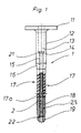
- Fig. 1 ein im unteren Bereich teilweise geschnittenes Befestigungselement,
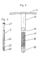
- Fig. 2 eine zugehörige Seitenansicht des Befestigungselementes in
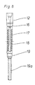
Figur 1, - Fig. 3 die Ansicht der zum Befestigungselement zugehörigen Kopfschraube,
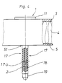
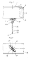
- Fig. 4 eine Einbausituation des Befestigungselementes an einem wärmeisolierenden Dachaufbau nach dem Durchstecken eines Befestigungselementes,
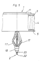
- Fig. 5 eine Figur 4 entsprechende Darstellung am Beginn des Anziehens der Schraube des Befestigungselementes zur Darstellung des Verdrillungsvorganges der Stege,
- Fig. 6 die Figur 4 entsprechende Darstellung in der Befestigungsposition, in der die Stege Anlageelemente bilden,
- Fig. 7 eine zugehörige Unteransicht zur Darstellung in Figur 6
und - Fig. 8 eine Variante des Befestigungselementes.
- 1 is a partially cut fastening element in the lower area,
- 2 shows an associated side view of the fastening element in FIG. 1,
- 3 shows the view of the head screw associated with the fastening element,
- 4 shows an installation situation of the fastening element on a heat-insulating roof structure after a fastening element has been pushed through,
- 5 shows a representation corresponding to FIG. 4 at the start of tightening the screw of the fastening element to illustrate the twisting process of the webs,
- 6 shows the representation corresponding to FIG. 4 in the fastening position in which the webs form contact elements,
- 7 is a corresponding bottom view for illustration in FIG. 6
and - Fig. 8 shows a variant of the fastener.
Zunächst wird auf die Figuren 1 - 3 Bezug genommen. Das insgesamt mit der Ziffer 1 bezeichnete Dübelelement aus Kunststoff besteht aus einer im Grundriß etwa rechteckigen Haltescheibe 11 und der daran etwa mittig nach unten angeformten rohrförmigen Vertiefung 12. Diese rohrförmige Vertiefung 12 geht über in einen konischen Absatz 16, an dem zwei sich diametral gegenüberliegende Stege 17 anschließen, die am Ende materialeinheitlich durch die mit der Ziffer 19 bezeichnete Kunststoffhülse verbunden sind. Die Stege 17 sind an ihren Außenkanten etwa mittig mit einer Einkerbung 17a versehen, die die Ausknickung der Stege begünstigen. Außen sind an den Stegen 17 jeweils zueinander parallele, schräg gerichtete Nuten 18 vorgesehen. Eine zugehörige Befestigungsschraube 2, wie sie insbesondere aus Figur 3 ersichtlich ist, wird durch die Bohrung 13 in das Dübelelement 1 eingeführt. Sie stützt sich mit ihrem Kopf 21 an dem konischen Abschnitt 14 im Inneren der rohrförmigen Vertiefung 12 ab. Der Schraubenschaft ist durch die Bohrung 15 im Dübelelement 1 hindurchgeführt, vorbei an den beiden Stegen 17. Mit seinem selbstschneidenden Gewindeende 22 greift die Schraube 2 in die Kunststoffhülse 19 ein. An das selbstschneidende Gewindeende 22 schließt ein Gewindeabschnitt 23 an, der in der Hülse 19 zu einer Schwergängigkeit gegenüber dem vorangegangenen Abschnitt führt. Diese Schwergängigkeit kann erreicht werden über eine größere Steigung oder über eine entsprechende andere Strukturierung der Oberfläche des Abschnittes 23. An den Abschnitt 23 schließt wiederum ein Gewindeabschnitt 24 mit normaler Steigung an, die beispielsweise der Steigung des Abschnittes 22 entsprechen kann.First, reference is made to FIGS. 1-3. The dowel element made of plastic, designated overall by the
Wie insbesondere aus Figur 4 ersichtlich, wird das Dübelelement 1 durch eine entsprechende Bohrung in einem Isolieraufbau, beispielsweise eines Daches, eingebracht. Diese Bohrung hat in der Regel einen etwas geringeren Durchmesser als der Außendurchmesser der rohrförmigen Vertiefung 12 des Dübelelementes 1 im oberen Bereich einer das Isoliermaterial 4 abdeckenden Kunststoffolie 3. Die rohrförmige Vertiefung 12 setzt mit ihrem Absatz 16 auf einer mit der Ziffer 5 angedeuteten Abstützplatte 5 auf, die das Isoliermaterial 4 nach unten abdeckt. Durch die Bohrung 51 in dieser Abstützplatte 5 ragen die Stege 17 des Dübelelementes 1 mit ihrer endseitigen verbindenden Kunststoffhülse 19 und der aufgenommenen Schraube 2 hindurch.As can be seen in particular from FIG. 4, the
Erfolgt nunmehr von oben her die Verdrehung der Schraube 2 mit einer geeigneten Drehgeschwindigkeit, in der Regel mit einem angetriebenen Schrauber, so schraubt sich zunächst das selbstschneidende Gewindeende 22 durch die Hülse 19 hindurch. Gelangt der schwergängige Gewindeabschnitt 23 in die Hülse, so wird bei geeigneter Drehgeschwindigkeit die Hülse 19 um einen bestimmten Drehwinkelbereich zwischen 30 - 90°, vorzugsweise 45°, in Drehrichtung mitgenommen, dabei verdrillen sich die Stege 17 in die in Figur 5 dargestellte Position und knicken dabei aufgrund der sich auf den Schraubenkopf zu bewegenden Hülse 19 aus. Es gelangt dann der Gewindeabschnitt 24 in den Bereich der Hülse 19. Ohne weitere Verdrillung bewegt sich die Kunststoffhülse 19 weiter auf den Schraubenkopf zu, die beiden Stege 17 knicken weiter in der verdrillten Position aus und kommen in der Endsituation zur Anlage an der Abstützplatte 5, wie in den Figuren 6 und 7 dargestellt. In dieser Lage bilden die um einen bestimmten Winkelbereich verdrillten und ausgeknickten Stege 17′ senkrecht zur Schraubenachse abspreizende Anlageelemente, die mit ihrer Unterseite vollständig an der Abstützplatte 5 anliegen. Das Dübelelement 1 ist in dieser Situation am Isolieraufbau beidseitig fest eingespannt.If the
Bei einem Dübelelement entsprechend Figur 8 ist gegenüber dem Dübelelement nach Anspruch 1 an der Kunststoffhülse 19 noch ein schlauchartiges Teil 19a vorgesehen, welches das in der Befestigungssituation herausragende Schraubenende kaschiert.In the case of a dowel element according to FIG. 8, a hose-like part 19a is provided on the
Claims (4)
Priority Applications (1)
| Application Number | Priority Date | Filing Date | Title |
|---|---|---|---|
| AT90107328T ATE78324T1 (en) | 1989-05-20 | 1990-04-18 | FASTENING ELEMENT FOR FIXING PANEL-LIKE THERMAL INSULATION. |
Applications Claiming Priority (2)
| Application Number | Priority Date | Filing Date | Title |
|---|---|---|---|
| DE3916515 | 1989-05-20 | ||
| DE3916515A DE3916515C1 (en) | 1989-05-20 | 1989-05-20 |
Publications (2)
| Publication Number | Publication Date |
|---|---|
| EP0399210A1 EP0399210A1 (en) | 1990-11-28 |
| EP0399210B1 true EP0399210B1 (en) | 1992-07-15 |
Family
ID=6381084
Family Applications (1)
| Application Number | Title | Priority Date | Filing Date |
|---|---|---|---|
| EP90107328A Expired - Lifetime EP0399210B1 (en) | 1989-05-20 | 1990-04-18 | Fastener for fastening of plate-shaped heat-isolating material |
Country Status (3)
| Country | Link |
|---|---|
| EP (1) | EP0399210B1 (en) |
| AT (1) | ATE78324T1 (en) |
| DE (1) | DE3916515C1 (en) |
Families Citing this family (10)
| Publication number | Priority date | Publication date | Assignee | Title |
|---|---|---|---|---|
| DE9410723U1 (en) * | 1994-07-02 | 1994-12-22 | Zahn Harald Gmbh | Non-slip fastening element for insulation and sealing material on flat roofs |
| DE9417927U1 (en) * | 1994-11-09 | 1995-01-12 | Zahn Harald Gmbh | Fastening element for insulation and sealing material on flat roofs |
| DE19520110C1 (en) * | 1995-06-01 | 1997-01-30 | Trurnit Friedrich Gmbh Co Kg | Device for introducing fasteners into plate-like thermal insulation material on roofs or the like |
| DE10062939A1 (en) * | 2000-12-16 | 2002-07-25 | Zahn Harald Gmbh | Flat roof sealing and insulating material fixer comprises screw in hollow shaft of plastics holder so screw penetrates and engages core of dowel leader via crush zone and engages roof invisibly via closed dowel cap. |
| NL1036675C2 (en) * | 2009-03-06 | 2010-09-07 | Gebrema B V | FIXING ORGANIZED FOR FIXING A FLAT OBJECT ON A SUBSTRATE. |
| CN102251597B (en) * | 2011-04-26 | 2013-01-02 | 南京科光高分子复合材料有限公司 | Heat preservation nail for anchoring heat preservation plate of cold storage |
| DE102013114653A1 (en) | 2013-10-15 | 2015-04-16 | Ludwig Hettich & Co. Kg | Anchoring system with a sleeve element and a spreading element |
| US20150121792A1 (en) | 2013-11-06 | 2015-05-07 | Owens Corning Intellectual Capital, Llc | Composite thermal isolating masonry tie fastener |
| DE102017102562A1 (en) * | 2017-02-09 | 2018-08-09 | CG Rail - Chinesisch-Deutsches Forschungs- und Entwicklungszentrum für Bahn- und Verkehrstechnik Dresden GmbH | Connecting element for connecting a component to a fiber composite structure |
| IT202100014663A1 (en) * | 2021-06-04 | 2022-12-04 | Allfix Italia S R L | WALL FIXING DEVICE |
Family Cites Families (2)
| Publication number | Priority date | Publication date | Assignee | Title |
|---|---|---|---|---|
| DE3516343A1 (en) * | 1985-05-07 | 1986-11-13 | Artur Dr.H.C. 7244 Waldachtal Fischer | DUEBEL |
| DE3713686A1 (en) * | 1987-04-24 | 1988-11-17 | Trurnit Friedrich Gmbh Co Kg | FASTENING ELEMENT |
-
1989
- 1989-05-20 DE DE3916515A patent/DE3916515C1/de not_active Expired - Lifetime
-
1990
- 1990-04-18 EP EP90107328A patent/EP0399210B1/en not_active Expired - Lifetime
- 1990-04-18 AT AT90107328T patent/ATE78324T1/en not_active IP Right Cessation
Also Published As
| Publication number | Publication date |
|---|---|
| ATE78324T1 (en) | 1992-08-15 |
| EP0399210A1 (en) | 1990-11-28 |
| DE3916515C1 (en) | 1990-11-08 |
Similar Documents
| Publication | Publication Date | Title |
|---|---|---|
| DE3000697C2 (en) | ||
| EP0282445B1 (en) | Fastener with a nail and a sleeve | |
| EP1767719A2 (en) | Fixing device for fastening solar panels to a C-shaped mounting rail | |
| DE10357844B4 (en) | fastening system | |
| WO1988005487A1 (en) | Fastening element with large-area plain washer | |
| EP0399210B1 (en) | Fastener for fastening of plate-shaped heat-isolating material | |
| EP1826507A2 (en) | Mounting device for mounting solar panels on a mounting rail | |
| EP2157324A2 (en) | Screw with sealing disc assembly | |
| DE4019157C1 (en) | ||
| EP0307647A1 (en) | Washer | |
| DE3120132A1 (en) | FASTENING ELEMENT | |
| EP0288023B1 (en) | Connecting element | |
| EP1222406B1 (en) | Retaining element for cap screws | |
| EP2667041A1 (en) | Fastening set for a composite fibre component | |
| DE3823000C2 (en) | Fastener | |
| EP0551836B1 (en) | Screw joint between a profile and a fitting or other structural member | |
| DE2433669A1 (en) | Press-stud type fixing for large roof sheets - esp. for polyamide or polypropylene with central expanding plug to lock | |
| EP2278171B1 (en) | Fixing element and system for mounting parts | |
| DE60023115T2 (en) | CONNECTION SYSTEM WITH A SLEEVE FOR COMPACT HOLDING OBJECTS | |
| DE19857225B4 (en) | screw | |
| DE10020218A1 (en) | Assembly unit consisting of one component and at least one thread-forming screw | |
| EP0182238B1 (en) | Pipe clamp | |
| DE4021245C2 (en) | ||
| DE202020101103U1 (en) | Pipe clamp and construction kit for their creation | |
| EP0801233A1 (en) | Distance adjusting screw |
Legal Events
| Date | Code | Title | Description |
|---|---|---|---|
| PUAI | Public reference made under article 153(3) epc to a published international application that has entered the european phase |
Free format text: ORIGINAL CODE: 0009012 |
|
| AK | Designated contracting states |
Kind code of ref document: A1 Designated state(s): AT BE CH FR GB LI LU NL SE |
|
| 17P | Request for examination filed |
Effective date: 19901024 |
|
| 17Q | First examination report despatched |
Effective date: 19911219 |
|
| GRAA | (expected) grant |
Free format text: ORIGINAL CODE: 0009210 |
|
| AK | Designated contracting states |
Kind code of ref document: B1 Designated state(s): AT BE CH FR GB LI LU NL SE |
|
| REF | Corresponds to: |
Ref document number: 78324 Country of ref document: AT Date of ref document: 19920815 Kind code of ref document: T |
|
| ET | Fr: translation filed | ||
| GBT | Gb: translation of ep patent filed (gb section 77(6)(a)/1977) | ||
| PG25 | Lapsed in a contracting state [announced via postgrant information from national office to epo] |
Ref country code: LU Free format text: LAPSE BECAUSE OF NON-PAYMENT OF DUE FEES Effective date: 19930430 |
|
| PLBE | No opposition filed within time limit |
Free format text: ORIGINAL CODE: 0009261 |
|
| STAA | Information on the status of an ep patent application or granted ep patent |
Free format text: STATUS: NO OPPOSITION FILED WITHIN TIME LIMIT |
|
| 26N | No opposition filed | ||
| EAL | Se: european patent in force in sweden |
Ref document number: 90107328.8 |
|
| PGFP | Annual fee paid to national office [announced via postgrant information from national office to epo] |
Ref country code: AT Payment date: 19970423 Year of fee payment: 8 |
|
| PGFP | Annual fee paid to national office [announced via postgrant information from national office to epo] |
Ref country code: CH Payment date: 19970429 Year of fee payment: 8 |
|
| PG25 | Lapsed in a contracting state [announced via postgrant information from national office to epo] |
Ref country code: AT Free format text: LAPSE BECAUSE OF NON-PAYMENT OF DUE FEES Effective date: 19980418 |
|
| PGFP | Annual fee paid to national office [announced via postgrant information from national office to epo] |
Ref country code: SE Payment date: 19980422 Year of fee payment: 9 Ref country code: BE Payment date: 19980422 Year of fee payment: 9 |
|
| PG25 | Lapsed in a contracting state [announced via postgrant information from national office to epo] |
Ref country code: LI Free format text: LAPSE BECAUSE OF NON-PAYMENT OF DUE FEES Effective date: 19980430 Ref country code: CH Free format text: LAPSE BECAUSE OF NON-PAYMENT OF DUE FEES Effective date: 19980430 |
|
| REG | Reference to a national code |
Ref country code: CH Ref legal event code: PL |
|
| PG25 | Lapsed in a contracting state [announced via postgrant information from national office to epo] |
Ref country code: SE Free format text: LAPSE BECAUSE OF NON-PAYMENT OF DUE FEES Effective date: 19990419 |
|
| PG25 | Lapsed in a contracting state [announced via postgrant information from national office to epo] |
Ref country code: BE Free format text: LAPSE BECAUSE OF NON-PAYMENT OF DUE FEES Effective date: 19990430 |
|
| BERE | Be: lapsed |
Owner name: FRIEDR. TRURNIT G.M.B.H. Effective date: 19990430 |
|
| EUG | Se: european patent has lapsed |
Ref document number: 90107328.8 |
|
| REG | Reference to a national code |
Ref country code: GB Ref legal event code: IF02 |
|
| PGFP | Annual fee paid to national office [announced via postgrant information from national office to epo] |
Ref country code: GB Payment date: 20030206 Year of fee payment: 14 |
|
| PGFP | Annual fee paid to national office [announced via postgrant information from national office to epo] |
Ref country code: NL Payment date: 20030228 Year of fee payment: 14 |
|
| PGFP | Annual fee paid to national office [announced via postgrant information from national office to epo] |
Ref country code: FR Payment date: 20030417 Year of fee payment: 14 |
|
| PG25 | Lapsed in a contracting state [announced via postgrant information from national office to epo] |
Ref country code: GB Free format text: LAPSE BECAUSE OF NON-PAYMENT OF DUE FEES Effective date: 20040418 |
|
| PG25 | Lapsed in a contracting state [announced via postgrant information from national office to epo] |
Ref country code: NL Free format text: LAPSE BECAUSE OF NON-PAYMENT OF DUE FEES Effective date: 20041101 |
|
| GBPC | Gb: european patent ceased through non-payment of renewal fee |
Effective date: 20040418 |
|
| PG25 | Lapsed in a contracting state [announced via postgrant information from national office to epo] |
Ref country code: FR Free format text: LAPSE BECAUSE OF NON-PAYMENT OF DUE FEES Effective date: 20041231 |
|
| NLV4 | Nl: lapsed or anulled due to non-payment of the annual fee |
Effective date: 20041101 |
|
| REG | Reference to a national code |
Ref country code: FR Ref legal event code: ST |