EP0398643A2 - Offene Bauweise für ein Verwaltungssystem eines Datenverarbeitungssystems - Google Patents
Offene Bauweise für ein Verwaltungssystem eines Datenverarbeitungssystems Download PDFInfo
- Publication number
- EP0398643A2 EP0398643A2 EP90305216A EP90305216A EP0398643A2 EP 0398643 A2 EP0398643 A2 EP 0398643A2 EP 90305216 A EP90305216 A EP 90305216A EP 90305216 A EP90305216 A EP 90305216A EP 0398643 A2 EP0398643 A2 EP 0398643A2
- Authority
- EP
- European Patent Office
- Prior art keywords
- user
- objects
- data
- system management
- methods
- Prior art date
- Legal status (The legal status is an assumption and is not a legal conclusion. Google has not performed a legal analysis and makes no representation as to the accuracy of the status listed.)
- Withdrawn
Links
Images


Classifications
-
- G—PHYSICS
- G06—COMPUTING OR CALCULATING; COUNTING
- G06F—ELECTRIC DIGITAL DATA PROCESSING
- G06F16/00—Information retrieval; Database structures therefor; File system structures therefor
- G06F16/20—Information retrieval; Database structures therefor; File system structures therefor of structured data, e.g. relational data
- G06F16/28—Databases characterised by their database models, e.g. relational or object models
- G06F16/289—Object oriented databases
Definitions
- This invention relates to the system management of a data processing system, and more particularly to the use of an object oriented database in an open system management architecture.
- Object-oriented database systems allow the semantics of a given environment to be modelled as a set of objects and relationships among them. Moreover, in complex application environments, objects and their relationships usually show very complex internal structures and comprise larger numbers of properties. With today's database systems, which are generally based upon a classical data model (hierarchical, network, or relational), they tend to be tailored to represent rather simple entities, thus resulting in large semantic gaps when dealing with more complex entities. In part this is true because one conceptual entity must be represented by a number of database objects (for example, records, tuples and so on). An object-oriented database system differs in that it offers a data model that allows the user to represent one conceptual real world entity by exactly one object or object class.
- object-oriented model allows entities to be composed of subentities that are entities themselves, including recursive definition.
- object orientation There are several levels of object orientation: o Structurally object-oriented: Allows one to define data structures to represent entities of any complexity. o Operationally object-oriented: Includes generic operators to deal with complex objects in their entirety. o Behaviourally object-oriented: Borrows types from the object-oriented programming paradigm, a data model that incorporates features to define object descriptor types of any complexity together with a set of specific operators (abstract data types).
- an object-oriented database paradigm offers increased modelling power by providing the ability to handle semantically meaningful objects rather than normalised tuples or single records.
- Such an approach greatly reduces the semantic gap between the real world and the database representation, while at the same time offering a more precise semantic definition of our real world.
- system management refers to the facilities or tools used to manage the configurable domains that a user is exposed to in a data processing system environment.
- a domain may be those devices, users, distributed file system, subsystems, and networks in a system; where the system extends beyond a single machine.
- the system management facilities for each of the configurable domains may include the means to configure the system components when components are added or deleted from a system, means to configure a data processing system within a network of other data processing systems, and/or the means to diagnose failures in the system components or the system configuration, etc.
- system management is treated as an ancillary element of an operating system environment; made up of an assortment of disjoint tools which collectively offer the administrator/user the ability to manage and monitor various aspects of the system.
- Each facility, i.e. program, for each configurable domain is different. Not only does this facility provide a user interface to the domain, but it also understands the semantics of the data, the representation of the data, and where the configuration information is stored. Therefore, for each facility, the user is confronted with a different user interface, and a different representation of the data depending upon which configurable domain the user is currently dealing with. Furthermore, to compound the problems, generally the user interfaces are designed toward the operating system environment of the data processing system instead of towards the task that is to be achieved by the end user.
- a system for providing system management to a user of a data processing system comprising: means for representing data of a plurality of configurable domains in an object oriented database within the data processing system; and means for performing tasks on the data of the plurality of configurable domains, which means comprises a plurality of layers, wherein the layers are independently extendable, by a user, for each of the plurality of configurable domains.
- the present invention therefore allows a cohesive, and consistent technique for managing and monitoring a system to be provided.
- the knowledge of each configurable domain is moved into the data by using an object oriented database; thus providing a set of facilities extendable in the field.
- the invention enables the usability of the operating environment to be increased by creating an interface that represents the tasks to be performed by a user instead of being solely dependent upon the specific terminology of the operating system environment. It enables the tedious and complicated tasks of managing and monitoring systems to be simplified, where a system may vary from a single machine to a network of machines in a heterogeneous environment.
- a first one of the loosely coupled structural layers is a user interface, independent from a plurality of functions operating on the data represented in the object oriented database, the user interface receiving parameters from a user for specifying a user system management task to be performed on the objects.
- the first layer comprises means for invoking a second layer; the second layer comprising high level command means for performing at least one general operation related to the user system management task but independent of a relationship of the objects.
- the second layer comprises means for invoking a third layer; the third layer comprising means for performing at least one specific operation on at least one of the objects in response to the user system management task, independently of the object location.
- the configurable domains can comprise data for logical devices and real devices.
- the system further comprises means for extending the data of at least one of the configurable domains by adding objects to the object oriented database.
- the system may further comprise means for adding to the means for performing at least one specific operation on at least one of the objects in response to the user system management task.
- the user high level command means may be changeable by the user for customising and/or adding to the user system management tasks to be performed.
- the system can further comprise means for making changes to the user interface means.
- a system management technique can be provided which is open and extendable for the management of other objects and related end-user tasks.
- a method for managing a plurality of system components of a data processing system comprising: representing data of the system components across a plurality of configurable domains in a plurality of objects of an object oriented database; managing the objects consistently throughout the configurable domains by manipulating the objects through a structurally layered facility; and independently extending each of the layers for managing an additional system component.
- the layered environment spans from the task-based user interface to the low level functions of an operating system across all of the configurable domains of a system.
- the task-based user interface is geared toward the end-user and not the operating environment.
- the system and its configurable domains are described in a uniform and robust fashion by using an object-oriented paradigm. Since, the techniques used are extendable, the end user can add to their system management environment in any of the different layers of this invention.
- the set of configurable domains encapsulated by the architecture are, for example: (1) Devices (disks, printers, terminals and so on); (2) Filesystems/Logical Volumes; (3) Network Nodes; (4) Users and Groups; (5) Queues; (6) Subsystems; and (7) Error Reporting and Problem Management, etc.
- the System Management Architecture is based on two concepts. First, the architecture is highly open and extendable. By being open, a user can readily insert and remove the various aspects of the system management product. Second, the architecture uses an object paradigm for representing the description of the system, independent of its network context.
- the user interface layer is completely separate from the functions, tasks, and commands that provide the user tasks. To that end, the user is free to provide any user interface desired to represent the different tasks.
- the high-level commands layer also referred to as the task layer, is executable entities which provide high level functions. A user is able to add and remove any of the high level commands which allows the user to customise the functions of the tasks which the user may need to utilise. Consequently, a user can add to or delete from the user interface to reflect the new or deleted tasks.
- the methods layer views all of the entities in the system as objects. Given that there are objects, the methods define operations and actions that are to be performed on each object. As an example, in the area of devices, all of the devices, including real devices and logical devices, are viewed as objects. Methods are used to define and undefine, configure and unconfigure, start and stop, each of the objects within the system environment.
- the objects are executable entities which perform particular operations that apply to the particular objects under consideration. For example, if a user wants to start an object of type printer, the method to start the printer is invoked.
- the methods embody low level functions necessary to perform the operations against the object.
- a user can easily add methods, objects, and corresponding changes to a user interface to manage system components which were not originally provided for, such as by the manufacturer of the system management product. For example, if a user wanted to include a printer into the system which was not originally provided for, a user could add to the user interface the configuration of the printer, the user could add tasks that would add, delete, change, and show the printer, the user can then write the methods that apply operations to the printer object by utilising the next layer of this invention, the low level commands.
- the system management services include the kernel of the operating system, system libraries, system calls, and the object data manager.
- the system and method of this invention enables a single data representation across all of the configurable domains to be provided.
- the object oriented representation i.e. data structure, provides a uniform and consistent representation of all of the data in all of the configurable domains.
- a configurable domain represents its data through the object data manager.
- the object data manager sends to physical storage an internal representation such that the configurable domain can access and retrieve the data appropriately. All configurable domains are reading and writing through the same interface.
- the present system management architecture is based on two key concepts. First, the architecture is highly open and extendable. Second, the architecture uses an object paradigm for representing the description of the system, independent of its network context.
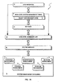
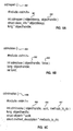
- Figure 1 outlines the layers of the system management architecture of the embodiment which provide an open and extendable facility.
- the user interface 20 is the windows, icons, menus, prompts, and choices presented to the user for the purposes of providing system management tasks.
- An illustration of a possible user interface menu 11 is shown in Fig. 2.
- the user interface 20 will collect the correct flags, parameters, and options and invoke the appropriate high-level command 30 to perform the desired task.
- the user interface level 20 has means for adding to the interface including adding menus, dialogs, and the corresponding commands.
- the System Management Interface Tool runs on all terminals. The fundamental point is that the user interface is an interchangeable entity within the system management architecture of this embodiment.
- Each high-level command 30 is written as a program or shell script 31, Fig. 2, following the argument syntax and rules as defined by POSIX 1003.2 Section 2.8.
- the high-level commands 30 execute any number of methods 40 and low level commands 50 in order to complete each user task. Because each high-level command 30 invokes methods 40 through the Object Data Manager (ODM) 10, the high-level commands 30 may be written in a network insensitive fashion to perform generic user tasks, independent of the network context of the object(s) to be manipulated.
- ODM Object Data Manager
- high-level commands 30 may be invoked from the shell 31, Fig. 2, without a sophisticated user interface 20.
- the high level commands can be either in shell script or a C program. Effectively the high level commands perform tasks. In the process of performing these tasks, the high level command invokes methods.
- Methods 40 are operations that apply to objects managed by the object data manager 10.
- the object data manager 10 provides the ability to associate operations to particular objects, thus providing the notion of "active" data.
- a method 40 is an executable program 41. The emphasis is for methods 40 to be entities that invoke a variety of low-level commands or low level functions 50 and other facilities that perform specific operations on specific objects.
- the object data manager 10 acts as a passive participant in the process and passes any or all text and return codes generated form the low-level commands 50 back to the application (high-level command 30) so that they may be diagnosed and reported. It is important to note that the high-level commands 30 invoke methods 40 representing operations that apply to a particular object, independent of the location of the object. Furthermore, new methods 40 may be created and associated with objects at any time.
- Methods are operations that apply to the objects that are being manipulated and/or configured.
- the methods are invoked through a method interface which is defined by the object data manager.
- the object data manager interface defines the method which needs to be invoked, optional arguments that are to be passed to the method, and pointers to the stderr and stdout buffers.
- the methods themselves can also generate output.
- the methods invoke commands and low level functions.
- the commands and low level functions also generate output which is returned to the methods, the methods return the generated output to the high level commands, and the output from the high level command is returned to the user interface which manages the output. Therefore, there is a synergy between the layers as output is returned.
- Low-level commands/interfaces 50 are fundamental. They typically provide simple, stateless, atomic operations and are quite often mapped on top of system level services 60, device drivers or subroutines, as executable entities.
- the low-level commands 50 are called by both methods 40 and high-level commands 30 and are written following the argument syntax and rules as defined by POSIX 1003.2 Section 2.8.
- the application programmer interface (API) 20 for each low-level command 50 is also available.
- System Management Services 70 include system calls, subroutines, device drivers and utilities provided by the kernel, Object Data Manager, Logical Volume Manager, configuration, etc., which support the low-level commands/interfaces 50 and their function.
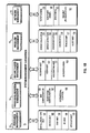
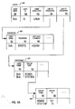
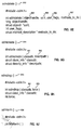
- each of the configurable domains 101-122, Fig. 1B may be represented, resulting in a consistent data representation across the different domains. Effectively, it has provided an environment whereby a great deal of the intelligence of the traditional application has been moved into the data.
- the object data manager 10 has a variety of methods that been defined for each of the specific object classes, which represent operations that may be applied to each object. For each object, the object specific processing represented by a particular method is performed here, completely insulating all other layers of the details.
- methods 621-624 have been developed to define 621, undefine 623, configure 622, unconfigure 624, start, stop, test, and problem manage each logical or physical device objects, etc.
- the object data manager offers the ability to: o Define arbitrarily complex data types (called descriptors) o Define relationships statically and dynamically between object classes/objects o Apply inheritance such that objects share descriptor values in both a vertical and horizontal direction o Provide a pseudo transactional processing mode which supports the undo of logical versions o Associate methods and triggers with objects o Support authorisation such that access control lists may be associated with each object
- the object data manager 10 provides to the application writers the ability to create, relate, manage and manipulate object classes and their objects, without having an understanding of how the data is stored, and without having an understanding of what is needed to perform the operations on the objects. This offers a very powerful tool for representing complex objects and subobjects. In keeping with object orientation, the object data manager allows the user to define methods and triggers that relate operations to each object class or object.
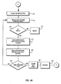
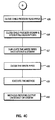
- Figs. 3A-3B illustrate the flow of the system and method of this embodiment.
- a user begins at the top of the tree of the user interface 20 and navigates iteratively through the tree, step 301 until the appropriate dialog is reached, step 302, in which the users wishes to enter data, change data, or list data, etc.
- the user interfaces with the dialog, step 303, as indicated. Since a dialog represents an action, such as show data, delete data, add data, etc., the dialog is then executed, step 304.
- the executed dialog may be either adding a disk to a system, adding a user to a system, showing all the devices on the system, showing all the users on the system, deleting devices, or deleting users, etc., depending upon the configurable domain which the user is currently interacting with, and the action represented by the dialog which is chosen by the user.
- the user interface 20 is a veneer which sits on top of the high level commands.
- the user interface 30 effectively executes the executable command, such as shown in Fig. 8A-8J, with all of its options, flags, parameters, that had been filled in at step 303 and step 304 which enabled the dialog.
- the user interface code performs the same function as shown and described later with reference to Fig. 4A in the way in which communication channels are managed.
- a communication channel is set up for reading standard error and standard output of the high level command that is invoked which is similar to the ODM method invocation facility.
- step 304 the high level command layer 30 is executed, step 306.
- Step 307 checks that the input parameters, options, flags, etc., that have been passed into it are valid. If any of these are not valid, step 308, an error is returned as an error message on the stderr communication channel. If an error is returned in text on the stderr communication channel, and the command was invoked from the user interface, at step 306, the user interface can read the error message and display the errors back to the user at step 303.
- step 308 the flow continues at step 309 Fig. 3B.
- the high level command would request that the object data manager open up the appropriate object class, or classes, where the objects are found, step 309, and perform the appropriate operations on those objects, step 310.
- the methods which are operations that apply to the objects, can either be invoked as part of the ODM call, step 311, such as the, show command, delete command, etc. as illustrated in odmget 812, Fig. 8F and odmadd 808, Fig. 8D, or after the operation is executed on the object, step 313.
- step 401 of Fig. 4A is implemented either after step 311 or after step 319.
- step 321 determines if the high level tasks are completed. If the high level tasks are completed, the appropriate object class, or classes, is closed, step 314. The appropriate text on standard output and standard error is then returned, step 315.
- the invocation of the methods causes the ODM to execute the appropriate code to invoke the method, Fig. 4A.
- the object data manager supports an invoke call which takes a method structure 701 Fig. 7, as its input, step 401.
- the object data manager takes the parameters 703, Fig. 7, the method name 702, and searches in the data base for the appropriate method that pertains to the object.
- the object data manager invoke code insures that the method structure parameters, object handles, and pointers are valid, step 402. If all of the parameters are valid, step 403, the object data manager xsystem routine is called, step 406, and opens two pairs of read/ write communication pipes for standard output and standard error, step 407.
- the child is forked, step 408, by making an identical process to the parent.
- Step 409 checks to see which of these two processes is the child between the identical copies.
- the parent process closes all of the write pipes, step 412, Fig. 4B, that were opened from step 407.
- the parent process selects on the read pipes waiting for input, step 413.
- the parent process blocks on the select() waiting for output from the child, step 415. If output comes from the child process, step 414, the parent process reads the appropriate pipe, either standard error or standard out, step 418. From the read in step 417, the parent process fills in the appropriate incore buffer with the text that is being read from the stderr or the stdout communication channel, step 418.
- the parent process then loops back to the select, step 413 waiting for more output from the child process.
- a signal handler is used to catch the death of the child process, step 419.
- the parent cleans out the pipes, step 421, and returns, step 423.
- step 409, Fig. 4A the child process closes the read pipes, step 425 Fig. 4C, that were created in step 407 Fig. 4A. Then, the child's standard out and standard error file descriptors are closed, step 426.
- the child process duplicates the write pipes, step 427, that were opened in step 407, Fig. 4A, onto the closed stderr and stdout file descriptors. After, stderr and stdout are attached to the write pipes that were opened, then the write pipes are closed, step 428.
- the appropriate method is then executed, step 429. If the method returns output on stdout or stderr, the parent can catch the output, step 430.
- This xsystem code Fig. 4A - 4C performs the equivalent of a popen system call and a fork/exec system call as known in association with the UNIX operating system as described in the AIX Operating System Technical Reference, second edition, September 1986, order number SV21-8009, part number 74X9990.
- the interface 20 can capture the standard output.
- the standard output is the output from the high level commands such as the listing of the disks on the system, etc.
- the valid output comes out on the channel which is referred to as the standard output channel in the UNIX operating system.
- the interface also has the ability to capture the output from stderr, stderr output (the error output), of the high level command.
- the interface 10 can then display, scroll, and manage either standard output or standard error.
- Fig. 2, Fig. 6, Fig. 5A, and Fig. 5B illustrate the uniform operation of the system management facility of this embodiment across configurable domains through the loosely coupled layers within the system management facility in conjunction with an object oriented representation of the configuration data.
- the user interface 20 creates a dialog for the configurable domain of devices 102, Fig. 1B, by asking for the volume group name, the size, the node, and what logical volumes are in it.
- the high level command 30 performs an odmopen 802 on the customised devices object class 601 on a particular node.
- the high level command 30 also attempts to perform an odmget 812 on the volume group name to make sure the volume group does not already exist.
- the high level command 30 then invokes the add method 40 passing the appropriate parameters such as the volume group name, the logical volumes, and the size, etc. Then the high level command 30 performs an odmclose 804.
- the vg_add method effectively adds objects of type logical volume group (lvg) to the customised devices object class 601, and to the customised attribute object class 631.
- the high level command 30 opens the appropriate object classes, adds the objects, closes the object classes, and returns any text.
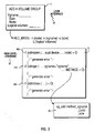
- Fig. 6 shows an example of the customised devices definition 601.
- the object class customised devices 601 is part of the device management configurable domain 102, Fig. 1B.
- the configurable domain devices includes both real devices and logical devices.
- the names "hdisk0" 602, "lp0" 603, “tty0” 604, “ttyl” 605, and "sa0" 606 represent names of physical entities, such as hard disks, line printers, terminals, and a serial adapter, on a system. These are device objects of type physical.
- Volume group 1, vg1, 607 and volume group 2, vg2, 608 are logical entities, i.e. objects. They are devices of type logical.
- logical devices represent groupings of physical disks that make up volume groups in the logical volume manager.
- the system management facility of this embodiment allows the same configuration object class to represent both physical and logical devices.
- a link signifies that there is a relationship to another object class.
- the operation of the object data manager is illustrated with reference to Fig. 6 as follows.
- the data, e.g. devices 612, are defined through the fields 613-640.
- the object data manager will transparently traverse the links 630 to the object classes 631 that relate to the object class that is being searched. For example, if a user opens up the customised object class 601 and requests all of the data for hdisk0 602, the object data manager would retrieve all of the information in the customised devices 601 and the customised attributes 631 relating to hdisk0 602.
- the executable methods 621-624 are columns within the object class 601.
- the executable program for the methods can be found in the files defined by the path names within the column fields.
- the define method 621 for hdisk0 602 is found through the path name "/etc/sysmgt/hdisk_dfmeth".
- the object data manager invokes a method 621-625, the method is executed.
- a config method 622 for hard disks there is a config method 622 for hard disks.
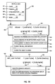
- FIG. 1B Another configurable domain, user management 110, Fig. 1B, is illustrated with reference to Figures 5A and 5B which illustrates how one would use a user object 950 in the object data manager.
- a user interface 920 defines the appropriate dialog that is needed, for example, to add a user.
- the dialog 920 would ask for the user name 921, the password 922, the home directory 923, the groups 924 that the user wants to belong to, and the node 925 that the user is to be added to.
- the high level command makeuser, mkuser 930 would be invoked.
- the high level command 930 takes all of the parameters 931-935 that were entered in the dialog 920.
- the high level command 930 validates the parameters for syntactical integrity, 936, issues an odmopen 802 (Fig. 8A) on the appropriate object class, e.g. users 950 Fig. 5A, and issues and odmget 812 (Fig. 8F) to ensure that the user does not already exist, 938. Issuing the odmget could also be found in a method.
- the high level command 930 invokes the add_user method 940 to add the user object to the object classes.
- the add_user method again takes the set of parameters 931-935 to validate the semantic integrity by determining whether a user already exists, and whether the groups exists, 941. If these do not already exist, the method 940 adds the user to the appropriate object class 950 (Fig. 9A), and updates or adds the appropriate group information, 942. All of this would be done by calling the appropriate low level functions.
- Fig. 5A represents an example of data that would be added by the method 940 of Fig. 5B.
- Fig. 5A also illustrates an example of object classes representing user information.
- a user object class 950 has a user name 951, user id 952, the home directory 953, etc.
- a link 954 to the password object class 960 contains the user name 951, the user password 961, and the date the password was last changed 962, and other relevant information.
- the password object class 960 is a separate object class for security requirements.
- the user object class 950 there would also be a link to a groupmap 970 which would provide the relationship between the users and the groups that the users belonged to.
- the user Bob belongs to the admin group and the system group.
- the groupmap object class 970 has a link 971 to a group object class 980 where the group ids 982 can be obtained along with other relevant information on the groups themselves.
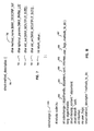
- Figures 8A-8J illustrate some of the calls and data structures that utilise the object data manager and invoke methods. Both the high level commands and the methods utilise this interface to the object data manager.
- the odmget 812, Fig. 8F specifies the criteria of the objects to be retrieved, passes the parameters, and invokes the methods for the retrieved object.
- the method structure 837 contained within the odmget call 812, Fig. 8F, and the odmadd call 808, Fig. 8D, is shown as 701 in Fig. 7.
- a user would supply method names 702 to invoke, any optional parameters 703 that need to be passed down to the method, whether the output of the method is to be returned on stdout 704, and whether the error is to be returned on stderr 705.
- the method is then executed.
- the object data manager supplies the return code value 706 of the method.
- the object data manager supplies the buffer information for stdout 704 and stderr 705 from the code as flowcharted in Figs. 4A-4C.
- the subroutine odmopen() 802, Fig. 8A opens the object class and locks in the manner defined through either the class_info structure or the ODM_env structure. If EXPAND is specified, all of the class's subclasses are opened also. objecthandle 832 filled in by odmopen() and will be the ID for this object class. This variable will be used by most of the ODM subroutines. Upon successful completion, the odmopen() subroutine returns the number of columns in the expanded object. If the subroutine fails, a value of -1 is returned.
- the subroutine odmclose() 804, Fig. 8B performs a virtual close of an object class.
- the object class is not actually purged from memory unless an odmopen() at some later time runs out of available slots. In this case, those object classes which have been odmclosed will actually be closed out.
- the force flag provides the capability of forcing the requested object class to actually be closed out.
- the subroutine odminvoke() 806, Fig. 8C invokes a method for the specified object(s). This provides the capability of invoking methods without adding, changing, deleting, or retrieving objects. Upon success completion, a value of O is returned. If the odminvoke() subroutine fails, a value of -1 is returned.
- the subroutine odmadd() 808, Fig. 8D given the object class to add to and the corresponding data, will add a new object to the object class. You can add one object to each sub-class of this object class. If inherit substitution is done, then the values to be added will be replaced by the inherit constant if they exactly match the corresponding value.
- an ID for the object is returned ( 0). If the odmadd() subroutine fails, a value of -1 is returned.
- user_flags 836 specifies whether you are deleting from the expanded object class, and whether you are deleting the inherit object or want inherit substitution done. Should be one of EXPAND or NOEXPAND logically or'd with one of DO_TO_INHERIT, DO_INHERITING or ODM_DEFAULT. The inherit object must exist if either inheriting options are specified.
- methods_to_do 837 pointer to an array of method_description structures which indicate the methods to execute when the delete is performed. Only the methods which are indicated are executed.
- a value of 0 is returned. If the odmdelete() subroutine fails, a value of -1 is returned.
- the subroutine odmget() 812, Fig. 8F given the object class, will retrieve the objects from the class which meet the search criteria. If the object class is made of compound object classes, the user can elect to either expand the output or not. In addition, this subroutine will support the buffer in ODM, STANZA, or COLON format.
- the odmget() subroutine needs to be called iteratively in order to fetch multiple objects meeting the selection criteria. This is accomplished in the following manner: 1) to get the first object provide a valid ucrit address to point to a valid search structure 2) for each subsequent call to get the NEXT object, supply a ucrit address of NULL.
- the ODM uses noncontiguous allocation schemes, it will perform the dynamic allocation of memory on behalf of the caller. It is important that both the ODM and the caller properly manage this dynamic memory. Specifically, the user may pass to odmget() different descriptor pointers for the purposes of caching multiple objects from any number of object classes at the same time. If this is so and the pointers passed to odmget() are automatic variables, odmfreeget() must be called before exiting the local function (this will free the memory). If the caller is using pointers which are not automatic, then one does not need to worry about calling odmfreeget(). The motivation for odmfreeget() is to ensure that the ODM is not continually allocating memory to pointers which are transient and thus resulting in dangling memory with no way to manage it.
- the odmget() subroutine Upon successful completion, the odmget() subroutine returns the number of descriptors. If the subroutine fails, a value of -1 is returned.
- the subroutine odmcreate() 814, Fig. 8G will create an empty object class by establishing the necessary directory structures and creating the necessary files.
- the object class will be created at the location determined by the node and availability scope in the class_info structure. If the object class is created successfully, it will be registered with the appropriate Object Manager.
- the object class name must be unique within its availability scope.
- a value of 0 is returned. If the odmcreate() subroutine fails, a value of -1 is returned.
- the subroutine odmdrop() 816, Fig. 8H, removes an entire object class and all of its objects. Not that there is no checking done to see if there are other object classes are linked to the object class to be removed.
- a value of 0 is returned. If the odmdrop() subroutine fails, a value of -1 is returned.
- a value of 0 is returned. If the odmchage() subroutine fails, a value of -1 is returned.
- the subroutine odmterm() 826, Fig. 8J notifies the ODM that no further ODM functions will be used so that all ODM internal data structures can be freed and all updates to the object repository are propagated to disk.
- the odminit() subroutine must be called again before using any of the ODM subroutines. Upon successful completion, a value of 0 is returned. If the odmterm() subroutine fails, a value of -1 is returned.
- This invention offers an environment that is layered, open and extendable, such that the end-user community may augment their system management tools and facilities with great ease. Furthermore, with the support provided by the object data manager, the system's definition is represented in a uniform and robust fashion.
Landscapes
- Engineering & Computer Science (AREA)
- Databases & Information Systems (AREA)
- Theoretical Computer Science (AREA)
- Data Mining & Analysis (AREA)
- Physics & Mathematics (AREA)
- General Engineering & Computer Science (AREA)
- General Physics & Mathematics (AREA)
- Information Retrieval, Db Structures And Fs Structures Therefor (AREA)
- Management, Administration, Business Operations System, And Electronic Commerce (AREA)
- Stored Programmes (AREA)
Applications Claiming Priority (2)
| Application Number | Priority Date | Filing Date | Title |
|---|---|---|---|
| US35257189A | 1989-05-15 | 1989-05-15 | |
| US352571 | 1999-07-13 |
Publications (2)
| Publication Number | Publication Date |
|---|---|
| EP0398643A2 true EP0398643A2 (de) | 1990-11-22 |
| EP0398643A3 EP0398643A3 (de) | 1992-12-23 |
Family
ID=23385671
Family Applications (1)
| Application Number | Title | Priority Date | Filing Date |
|---|---|---|---|
| EP19900305216 Withdrawn EP0398643A3 (de) | 1989-05-15 | 1990-05-15 | Offene Bauweise für ein Verwaltungssystem eines Datenverarbeitungssystems |
Country Status (2)
| Country | Link |
|---|---|
| EP (1) | EP0398643A3 (de) |
| JP (1) | JPH036638A (de) |
Family Cites Families (1)
| Publication number | Priority date | Publication date | Assignee | Title |
|---|---|---|---|---|
| JPS62115533A (ja) * | 1985-11-15 | 1987-05-27 | Fujitsu Ltd | 知識処理システム |
-
1990
- 1990-05-15 EP EP19900305216 patent/EP0398643A3/de not_active Withdrawn
- 1990-05-15 JP JP2123214A patent/JPH036638A/ja active Pending
Non-Patent Citations (1)
| Title |
|---|
| MICROPROCESSING AND MICROPROGRAMMING vol. 18, no. 1-5, 1986, AMSTERDAM NL pages 455 - 462 H.J.M.DECUYPERE 'Object oriented system supporting dynamic configuration' * |
Also Published As
| Publication number | Publication date |
|---|---|
| EP0398643A3 (de) | 1992-12-23 |
| JPH036638A (ja) | 1991-01-14 |
Similar Documents
| Publication | Publication Date | Title |
|---|---|---|
| US5335346A (en) | Access control policies for an object oriented database, including access control lists which span across object boundaries | |
| US7917538B2 (en) | Method and apparatus for data item movement between disparate sources and hierarchical, object-oriented representation | |
| US6427230B1 (en) | System and method for defining and managing reusable groups software constructs within an object management system | |
| US6226792B1 (en) | Object management system supporting the use of application domain knowledge mapped to technology domain knowledge | |
| US5551028A (en) | Design data management system and associated method | |
| US5787413A (en) | C++ classes for a digital library | |
| US6789251B1 (en) | System and method for managing a suite of data management tools | |
| US6507833B1 (en) | Method and apparatus for dynamically rendering components at run time | |
| JP2645430B2 (ja) | ユーザ・インタフェースを自動的にカスタム化するためのデータ処理システム | |
| US5859978A (en) | Managing application programs in a computer network by using a database of application objects | |
| US6128619A (en) | Generating an internet application for accessing a hierarchical database | |
| US6141660A (en) | Command line interface for creating business objects for accessing a hierarchical database | |
| US5187786A (en) | Method for apparatus for implementing a class hierarchy of objects in a hierarchical file system | |
| US6061689A (en) | Object aggregation representation of relational database rows having nontraditional datatypes | |
| US8296720B2 (en) | Framework to access a remote system from an integrated development environment | |
| US5832498A (en) | Device for generating object-oriented interfaces for relational data bases and a process implemented by this device | |
| US6430571B1 (en) | Multi-frame output form that facilitates internet search and update in a hierarchical database | |
| US5896532A (en) | Objects with run-time classes and methods of making them | |
| KR940002343B1 (ko) | 인터페이스 및 아이템 표시 방법 | |
| JP2023070148A (ja) | ロボティックプロセスオートメーション(rpa)ロボットをリソースへ動的にバインドさせるためのシステムおよび方法 | |
| US5890160A (en) | Object representation of relational database cells having nontraditional large object datatypes | |
| US6493704B1 (en) | Method and apparatus for using metadata to dynamically generate a display page to solicit input from a user | |
| Annighoefer et al. | EOQ: An open source interface for a more DAMMMMN domain-specific model utilization | |
| US6968340B1 (en) | Technique for navigating components of a model having complex relationships | |
| EP0398643A2 (de) | Offene Bauweise für ein Verwaltungssystem eines Datenverarbeitungssystems |
Legal Events
| Date | Code | Title | Description |
|---|---|---|---|
| PUAI | Public reference made under article 153(3) epc to a published international application that has entered the european phase |
Free format text: ORIGINAL CODE: 0009012 |
|
| AK | Designated contracting states |
Kind code of ref document: A2 Designated state(s): DE FR GB |
|
| 17P | Request for examination filed |
Effective date: 19901213 |
|
| PUAL | Search report despatched |
Free format text: ORIGINAL CODE: 0009013 |
|
| AK | Designated contracting states |
Kind code of ref document: A3 Designated state(s): DE FR GB |
|
| STAA | Information on the status of an ep patent application or granted ep patent |
Free format text: STATUS: THE APPLICATION IS DEEMED TO BE WITHDRAWN |
|
| 18D | Application deemed to be withdrawn |
Effective date: 19951201 |