EP0398055A2 - Flat touch screen workpad for a data processing system - Google Patents
Flat touch screen workpad for a data processing system Download PDFInfo
- Publication number
- EP0398055A2 EP0398055A2 EP90108082A EP90108082A EP0398055A2 EP 0398055 A2 EP0398055 A2 EP 0398055A2 EP 90108082 A EP90108082 A EP 90108082A EP 90108082 A EP90108082 A EP 90108082A EP 0398055 A2 EP0398055 A2 EP 0398055A2
- Authority
- EP
- European Patent Office
- Prior art keywords
- workpad
- housing
- touch panel
- user
- display
- Prior art date
- Legal status (The legal status is an assumption and is not a legal conclusion. Google has not performed a legal analysis and makes no representation as to the accuracy of the status listed.)
- Granted
Links
Images


Classifications
-
- G—PHYSICS
- G06—COMPUTING; CALCULATING OR COUNTING
- G06F—ELECTRIC DIGITAL DATA PROCESSING
- G06F3/00—Input arrangements for transferring data to be processed into a form capable of being handled by the computer; Output arrangements for transferring data from processing unit to output unit, e.g. interface arrangements
- G06F3/01—Input arrangements or combined input and output arrangements for interaction between user and computer
- G06F3/03—Arrangements for converting the position or the displacement of a member into a coded form
- G06F3/041—Digitisers, e.g. for touch screens or touch pads, characterised by the transducing means
- G06F3/0416—Control or interface arrangements specially adapted for digitisers
Definitions
- the present invention relates to a workpad serving as input and output device for a data processing system, having a touch panel and operating switches, as well as a data processing system for cooperation with such a workpad.
- Touch panels have been developed for use with cathode ray tube (CRT) display devices, the combination being connected to a data processor for use as both an input and output device.
- CRT cathode ray tube
- An example of such a system is described in U.S. patent 4,686,332-Greanias et al., "Combined Finger Touch and Stylus Detection System for use on the Viewing Surface of a Visual Display Device," said patent being assigned to the assignee of the present invention.
- the advantage of such a system is that a touch panel provides user friendly interaction with a data processing system.
- One disadvantage of such a system in accordance with the prior art is that because the touch panel is placed on the vertical viewing face of a CRT, the user has to reach out in order to touch the panel or use this stylus. When the user does this for an extended period of time, such action becomes tiresome, uncomfortable and tedious.
- CRT computed tomography
- a CRT is rather bulky and heavy, making it difficult to move the touch input device to positions which are more convenient or efficient for the user.
- Another disadvantage is that the CRT display uses coaxial cables or wires. Such coax wiring is relatively heavy and stiff which also detracts from the ability to readily move the display device from one position to another. Further, CRT displays consume considerable power requiring the use of a separate power cable. The CRT based devices therefore are operated at a fixed location.
- touch input devices and the attendant display screens have been limited by the availability of computer programs.
- the touch panels are used to select actions or graphic display panels in response to a user touch on particular menu selections displayed on the screen.
- Many more complex computer applications, particularly for a personal computer have been written for keyboard or mouse pointing device input. It would be an advantage to design a touch input device which could emulate the input of a wide variety of input devices, including the mouse and the keyboard, to take advantage of the many existing applications programs based upon such devices.
- the design objectives associated with the design of the invention are to provide a touch input device that is a significant improvement over existing touch screens, as well as other input devices in an office environment, that meet the following requirements: Input - detection of finger position - detection of stylus position for detail work - spatial resolution as good as current mouse devices - temporal resolution adequate for handwriting applications and mouse point-and-drag operations - support for multiple value input at each touch position, e.g., mouse buttons 1 and 2 - operation without a separate keyboard for most applications Display- - operation in office ambient lighting - support for IBM VGA video standard - support for at least 8 shades of gray - adequate contrast and viewing angle for day-long use - support for simultaneous use of standard color CRT Physical Configuration- - nearly horizontal orientation with adequate arm support - convenient laptop use for intensive thought tasks - flexible one cable attachment to computer
- Another object is to allow a maximum freedom of movement between the workpad and the rest of the data processing to which it is connected thereby permitting its use in positions or locations comfortable and efficient for the user, including a standing position.
- Still another object is to provide a high resolution workpad that can be readily moved about due in part to the use of a flexible coiled cable connected between the workpad and a data processor.
- Still a further object is to emulate a variety of types of input from a single touch input device, including touch, keyboard, mouse and gesture input data formats.
- Another object is to provide a touch panel display device that utilizes a liquid crystal display combined with an overlayed touch panel that is actuated by either a finger touch or a proximity of a stylus to the panel, with additional switches or buttons which are program controlled and may be used to emulate mouse buttons.
- a light weight relatively flat workpad connected by a flexible coiled cable to a personal computer.
- a liquid crystal display is mounted in the workpad and has a rectangular viewing face overlayed with a transplant touch panel.
- the stylus is connected to the workpad and the touch panel is activated by either a finger touch or by bringing the stylus into contact or near contact therewith.
- Electrical controls are partially mounted in the workpad and partially in the personal computer.
- At least one button switch is mounted on the workpad housing adjacent to the viewing surface and in such a position as to be selectively actuated by hand of the user while the other hand of the user is manipulating the stylus or touching the touch panel. Under program control, the switch can emulate a switch found on a mouse pointing device, a function key or a keyboard.
- a workpad 10 comprises a housing 12 provided with a rectangular recessed window 14 that surrounds the edges of a rectangular touch panel 16.
- Touch panel 16 is transparent and overlays an LCD 18 which, because of the rectangular window 14, provides a rectangular viewing surface.
- the combination of the touch panel and display is referred to hereinafter as a "touch screen" 19.
- Panel 16 includes a multiplicity of embedded, transparent conductors 16A orthogonally positioned relative to a multiplicity of conductors 16B.
- the resolution of stylus position provided by the orthogonal lines 16a and 16b correspond substantially to resolution provided by the number of pixels in LCD 18.
- Touch panel 16 is constructed similar to the touch panel described in the aforementioned US patent 4 686 332.
- a detection or pickup stylus 20 is connected by cable 22 to workpad 10 and is of a size similar to a pen or pencil such that the stylus can be manually grasped and moved about within constraints of the length of cable 22.
- Cable 22 is flexible to facilitate such movement and use.
- Stylus 20 has a tapered working end within which is enclosed a pickup coil (not shown) of a size relative the conductors 16 A and B that provides detailed resolution greater than that encounter when a finger is used to touch the panel, allowing the stylus to be used for work more detailed than that obtainable by use of finger touch.
- Housing 12 has two side opening recesses in which stylus 20 can be placed for storage.
- Housing 12 further has two upwardly facing recesses to accommodate the tip of the stylus whereby the stylus can be supported in a more readily available position, such as shown in Fig. 2, when not in use.
- Recesses 24 and 26 are lined with metal walls to shield the tip of the stylus and prevent unwanted pickup from the conductors 16 A and B when the stylus is out of use and stored away.
- Recesses 26 are located in the lower corners of housing 14 as viewed in Fig. 2.
- Window 14 and touch panel 16 and LCD 18 occupy most of the area of the top of workpad 10 and the housing surrounding the window is in the form of a rectangular annular frame, such frame having two laterally spaced rectangular recesses 28 formed in the sides near the top of such frame.
- Mounted in such recesses are four button switches 30-33, there being two switches at each side.
- the switches are round, when viewed as in Fig. 2, and are substantially flat having a thickness approximately the same as the depth of a recess 28.
- the switches are designed to be manually actuated by the fingers of a user. When used to emulate mouse buttons, the switches are set up for both left-handed and right-handed operation where, e.g., switches 31 and 33 are used as mouse button 1 and switches 30 and 32 are used as mouse button 2.
- buttons 30 and 31 are single pole, single throw, momentary action push button switches.
- the buttons can be programmed in software to provide various application-specific functions. For example, the buttons can be programmed to emulate the functions of mouse button 1 and button 2 when depressed. They can be programmed in software to operate as four independent buttons or as two sets of parallel buttons. Momentary action or latched action can also be defined by appropriate software.
- a tilt stand or support 34 is mounted on the underside of housing 12 and includes two laterally spaced arms 36 connected at one end to and mounted for rotation about pivot pins 38. The other ends of the arms are connected to and support a cylinder 40 of a soft plastic or rubber that extends between the two arms. Together, arms 36 and cylinder 40 form a U-shaped support 34 which is moveable between the full line position shown in Fig. 2 to the dotted line position. In any position along such path of movement, support 34 is frictionally held in place and will not give under the weight of workpad 10. When support 34 is in the full line position, cylinder 40 does not extend beneath the bottom flat surface 44 of housing 12. When moved to any other position, support 34 will support workpad 10 on a work surface at an angle up to about 35 degrees.
- the work surface could be a desk top or the lap of user.
- the bottom surface 44 and the top surface of housing 12 are flat and parallel to one another but spaced apart by the depth of the housing or workpad.
- the upper surface 42 is also horizontal, as is the touch panel and viewing face of the LCD so that the viewing face is exposed for view in such position.
- support 34 when used on the lap of the user, support 34 may or may not be used. Further, the support could be extended downwardly and grasped between the knees of the user to provide a more secure support than that provided merely by resting workpad 10 on the user's lap.
- the overall dimensions of workpad 10 are approximately 28 cm x 36 cm x 5 cm (11" by 14" by 2"), so that it is of a size that can be readily handled by a user and supported on a lap.
- Relative brightness and contrast control knobs 50 and 52 are mounted on the underside of housing 12 and exposed for manual rotation from the side thereof.
- the weight of workpad 10 is 1.8 kg.
- workpad 10 is connected to a personal computer 60 through a single cable 56.
- Computer 60 comprises a system unit 62, a display 64 and a keyboard 66.
- This figure also shows a user 70 supporting workpad 10 on the user's lap while the personal computer is supported on a table or desk top 72 at a distance from the user.
- Cord 56 has an extensible medial coiled portion 74 connected between two non-coiled ends 76.
- the extended length of cord 56 is preferably 4.80 m (sixteen feet) allowing the user to move the workpad to many different positions that are comfortable. Quite obviously, such length is illustrative only and other lengths can be used.
- cable 56 comprises an outer insulating sheath 80 surrounding two insulated wires 82 and 83 and two triple twisted wire cables 84 and 85. These latter cables house insulated wires 86, 87, and 88, and 90, 91 and 92.
- Wires 82 and 83 provide 0 and -5 volt power
- wires 88 and 91 provide +12 and -12 volt power
- wires 86 and 87 are signal wires for balanced transmission from the workpad to the computer
- wires 90 and 92 are signal wires for the balanced transmission from the computer to the workpad.
- Display 18 is connected through line 102 to an LCD control 100 which in turn is connected through line 104 to a bus 106.
- Interface 108 is connected to bus 106 and to cable 56 whereby operation of display is done with signals and commands sent over line 56 from the computer.
- Touch sensor 16 is connected to a sense mode frequency measurement circuit 110 and to a wire select multiplexer 114.
- a sensor driver 112 connects between mux 114 and bus 106, and operates to detect when and where a finger touches the tough screen.
- a button status circuit 116 is connected to the button switches 30-33 through line 117.
- Line 22 from the stylus is connected to a stylus input circuit 118 which in turn is connected to a stylus mode signal strength measurement circuit 120, the latter being connected to bus 106.
- a touch panel adapter card 126 is mounted in the computer and has an interface 122 connected to cable 56.
- a video processor 127 is connected to interface 122 and to the auxiliary video slot 128 of computer 60.
- Computer 60 includes standard items such as a CPU 132, ROM 134, Disk 136, keyboard 66, display 64 and a memory 138 which stores an operating system 140 and application program 142 for execution thereof.
- Card 126 also includes a bus 124 connected to interface 122 and to a ROM 144, RAM 146, control processor 148 and I/O controller 150. Controller 150 is connected to bus 130 through line 152.
- interface 122 includes a RAM 226 which receives and stores video signals and outputs 1/4 at a time to a multiplexer (mux) 224 so that the video display requires four frames of signal to fully change the display.
- Mux 224 provides signals over a 4B/5B encoder 222 to a parallel to serial converter 220 which outputs to a non-return to zero invert (NRZI) circuit 218 and a transmitter (trans) 216. Signals are transferred over lines 90 and 92 of cable 56 from trans 216 to a receiver (rcvr) 214. The signals then pass through a serial-to-parallel converter 210, 5B/4B decoder 208 and a demultiplexer 200. The latter provides separate signals on lines 202, 204 and 206 sending various signals to the display such as control, status query, sensor driver commands and video signals.
- the signals being transmitted from the display to the computer pass through the channel shown in Fig. 8 which is similar to the channel shown in Fig. 7.
- Input signals on lines 242, 244, 246 and 248 are inputted to MUX 240 and pass through encoder 250, converter 252, NRZI circuit 254, rcvr 256, lines 86 and 87, trans 258, NRZI circuit 260, converter 262, decoder 264 to a mux 266 where they are fed to the computer.
- Fig. 9 generally shows the manner in which buttons 30-33 are operated under program control.
- the button switches are connected respectively to a series of change of state registers 300 which in turn are connected to button state registers 302.
- Upon actuation of any switch it will enable its associated register and send to the associated register 302 a code specifically identifying the switch that was actuated and an interrupt signal will be sent over lines 117 to the computer 60.
- An interrupt handling routine will then query state register 302 and obtain therefrom the code signifying which switch was actuated. Deactuation of a switch will also cause an interrupt.
- Memory 138 stores the programs for interpreting the switches which will include device driver and emulation routines 304, an event generator, environment dependent routine 306 and application software 308.
- the emulation routines 304 can interpret the switches to represent mouse buttons or functions keys to enable the workpad to be used with application programs written for such support. Alternately, the application software 308 itself can interpret the keys directly.
Abstract
Description
- The present invention relates to a workpad serving as input and output device for a data processing system, having a touch panel and operating switches, as well as a data processing system for cooperation with such a workpad.
- Touch panels have been developed for use with cathode ray tube (CRT) display devices, the combination being connected to a data processor for use as both an input and output device. An example of such a system is described in U.S. patent 4,686,332-Greanias et al., "Combined Finger Touch and Stylus Detection System for use on the Viewing Surface of a Visual Display Device," said patent being assigned to the assignee of the present invention. The advantage of such a system is that a touch panel provides user friendly interaction with a data processing system. One disadvantage of such a system in accordance with the prior art is that because the touch panel is placed on the vertical viewing face of a CRT, the user has to reach out in order to touch the panel or use this stylus. When the user does this for an extended period of time, such action becomes tiresome, uncomfortable and tedious.
- The physical dimensions of a CRT make it difficult to design a display having a horizontal viewing surface upon which a touch panel can be mounted. Further, a CRT is rather bulky and heavy, making it difficult to move the touch input device to positions which are more convenient or efficient for the user. Another disadvantage is that the CRT display uses coaxial cables or wires. Such coax wiring is relatively heavy and stiff which also detracts from the ability to readily move the display device from one position to another. Further, CRT displays consume considerable power requiring the use of a separate power cable. The CRT based devices therefore are operated at a fixed location.
- In addition, the use of touch input devices and the attendant display screens have been limited by the availability of computer programs. Typically, the touch panels are used to select actions or graphic display panels in response to a user touch on particular menu selections displayed on the screen. Many more complex computer applications, particularly for a personal computer, have been written for keyboard or mouse pointing device input. It would be an advantage to design a touch input device which could emulate the input of a wide variety of input devices, including the mouse and the keyboard, to take advantage of the many existing applications programs based upon such devices.
- Improvements in the art of sensor and display technology now make the implementation of a workpad concept feasible. While prior art touch displays are acceptable for short, casual use tasks, they may not be feasible or suited for intensive use tasks. Recent improvements in the optical qualities (brightness, contrast, viewing cone) of flat panel displays, such as LCDs, allow implementing a touch screen for use in a horizontal orientation. This greatly improves the human factors for applications involving extensive pointing, drawing, or writing.
- The design objectives associated with the design of the invention are to provide a touch input device that is a significant improvement over existing touch screens, as well as other input devices in an office environment, that meet the following requirements:
Input
- detection of finger position
- detection of stylus position for detail work
- spatial resolution as good as current mouse devices
- temporal resolution adequate for handwriting applications and mouse point-and-drag operations
- support for multiple value input at each touch position, e.g., mouse buttons 1 and 2
- operation without a separate keyboard for most applications
Display-
- operation in office ambient lighting
- support for IBM VGA video standard
- support for at least 8 shades of gray
- adequate contrast and viewing angle for day-long use
- support for simultaneous use of standard color CRT
Physical Configuration-
- nearly horizontal orientation with adequate arm support
- convenient laptop use for intensive thought tasks
- flexible one cable attachment to computer - It is therefore an object of the invention to provide a touch panel display device or workpad that can be readily handled by a user and operated in a variety of positions, including a substantially horizontal position upon the user's lap or upon a desk top, as dictated by the convenience of the user and the need for adequate arm support.
- Another object is to allow a maximum freedom of movement between the workpad and the rest of the data processing to which it is connected thereby permitting its use in positions or locations comfortable and efficient for the user, including a standing position.
- Still another object is to provide a high resolution workpad that can be readily moved about due in part to the use of a flexible coiled cable connected between the workpad and a data processor.
- Still a further object is to emulate a variety of types of input from a single touch input device, including touch, keyboard, mouse and gesture input data formats.
- Another object is to provide a touch panel display device that utilizes a liquid crystal display combined with an overlayed touch panel that is actuated by either a finger touch or a proximity of a stylus to the panel, with additional switches or buttons which are program controlled and may be used to emulate mouse buttons.
- Briefly, in accordance with the preferred embodiment of the invention, the above objects and advantages are obtained by a light weight relatively flat workpad connected by a flexible coiled cable to a personal computer. A liquid crystal display is mounted in the workpad and has a rectangular viewing face overlayed with a transplant touch panel. The stylus is connected to the workpad and the touch panel is activated by either a finger touch or by bringing the stylus into contact or near contact therewith. Electrical controls are partially mounted in the workpad and partially in the personal computer. At least one button switch is mounted on the workpad housing adjacent to the viewing surface and in such a position as to be selectively actuated by hand of the user while the other hand of the user is manipulating the stylus or touching the touch panel. Under program control, the switch can emulate a switch found on a mouse pointing device, a function key or a keyboard.
- Improvements in the art of sensor and display technology now make the implementation of a workpad concept feasible. While prior art touch displays are acceptable for short, casual use tasks, they may not be feasible or suited for intensive use tasks. Recent improvements in the optical qualities (brightness, contrast, viewing cone) of flat panel displays, such as LCDs, allow implementing a touch screen for use in a horizontal orientation. This greatly improves the human factors for applications involving extensive pointing, drawing, or writing.
-
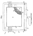
- Fig. 1 is a top view of a workpad designed in accordance with the present invention;
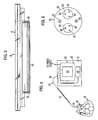
- Fig. 2 is a side view of the workpad shown in Fig. 1;
- Fig. 3 is an end view of the workpad shown in Fig. 1;
- Fig. 4 is a schematic diagram of a data processing system embodying the invention and showing one mode of interaction therewith by a user;
- Fig. 5 is a schematic cross-sectional view through the cable which connects the workpad to a personal computer as shown in Fig. 4;
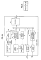
- Fig. 6 is a block diagram of certain of the electrical portions of the invention;
- Fig. 7 is a more detailed block diagram of the computer to display channel of communication;
- Fig. 8 is a more detailed block diagram of the display to computer channel of communication; and
- Fig. 9 is a block diagram useful in understanding the programmed operation of the button switches.
- Referring now to the drawings, and first to Fig. 1, a
workpad 10 comprises ahousing 12 provided with a rectangular recessedwindow 14 that surrounds the edges of arectangular touch panel 16.Touch panel 16 is transparent and overlays anLCD 18 which, because of therectangular window 14, provides a rectangular viewing surface. The combination of the touch panel and display is referred to hereinafter as a "touch screen" 19.Panel 16 includes a multiplicity of embedded,transparent conductors 16A orthogonally positioned relative to a multiplicity ofconductors 16B. The resolution of stylus position provided by the orthogonal lines 16a and 16b correspond substantially to resolution provided by the number of pixels inLCD 18.Touch panel 16 is constructed similar to the touch panel described in theaforementioned US patent 4 686 332. - A detection or
pickup stylus 20 is connected bycable 22 to workpad 10 and is of a size similar to a pen or pencil such that the stylus can be manually grasped and moved about within constraints of the length ofcable 22.Cable 22 is flexible to facilitate such movement and use.Stylus 20 has a tapered working end within which is enclosed a pickup coil (not shown) of a size relative theconductors 16 A and B that provides detailed resolution greater than that encounter when a finger is used to touch the panel, allowing the stylus to be used for work more detailed than that obtainable by use of finger touch.Housing 12 has two side opening recesses in whichstylus 20 can be placed for storage.Housing 12 further has two upwardly facing recesses to accommodate the tip of the stylus whereby the stylus can be supported in a more readily available position, such as shown in Fig. 2, when not in use.Recesses conductors 16 A and B when the stylus is out of use and stored away.Recesses 26 are located in the lower corners ofhousing 14 as viewed in Fig. 2. -
Window 14 andtouch panel 16 andLCD 18 occupy most of the area of the top ofworkpad 10 and the housing surrounding the window is in the form of a rectangular annular frame, such frame having two laterally spacedrectangular recesses 28 formed in the sides near the top of such frame. Mounted in such recesses are four button switches 30-33, there being two switches at each side. The switches are round, when viewed as in Fig. 2, and are substantially flat having a thickness approximately the same as the depth of arecess 28. The switches are designed to be manually actuated by the fingers of a user. When used to emulate mouse buttons, the switches are set up for both left-handed and right-handed operation where, e.g., switches 31 and 33 are used as mouse button 1 and switches 30 and 32 are used as mouse button 2. It is expected that a right-handed user would rest finger of his or her left hand on ornear buttons - A tilt stand or
support 34 is mounted on the underside ofhousing 12 and includes two laterally spacedarms 36 connected at one end to and mounted for rotation about pivot pins 38. The other ends of the arms are connected to and support acylinder 40 of a soft plastic or rubber that extends between the two arms. Together,arms 36 andcylinder 40 form aU-shaped support 34 which is moveable between the full line position shown in Fig. 2 to the dotted line position. In any position along such path of movement,support 34 is frictionally held in place and will not give under the weight ofworkpad 10. Whensupport 34 is in the full line position,cylinder 40 does not extend beneath the bottomflat surface 44 ofhousing 12. When moved to any other position,support 34 will supportworkpad 10 on a work surface at an angle up to about 35 degrees. The work surface could be a desk top or the lap of user. Thebottom surface 44 and the top surface ofhousing 12 are flat and parallel to one another but spaced apart by the depth of the housing or workpad. When thebottom surface 44 is resting on a flat horizontal surface, theupper surface 42 is also horizontal, as is the touch panel and viewing face of the LCD so that the viewing face is exposed for view in such position. - It should be appreciated that when used on the lap of the user,
support 34 may or may not be used. Further, the support could be extended downwardly and grasped between the knees of the user to provide a more secure support than that provided merely by restingworkpad 10 on the user's lap. The overall dimensions ofworkpad 10 are approximately 28 cm x 36 cm x 5 cm (11" by 14" by 2"), so that it is of a size that can be readily handled by a user and supported on a lap. Relative brightness and contrast control knobs 50 and 52 are mounted on the underside ofhousing 12 and exposed for manual rotation from the side thereof. The weight ofworkpad 10 is 1.8 kg. - Referring to Fig. 4,
workpad 10 is connected to apersonal computer 60 through asingle cable 56.Computer 60 comprises asystem unit 62, adisplay 64 and akeyboard 66. This figure also shows auser 70 supportingworkpad 10 on the user's lap while the personal computer is supported on a table ordesk top 72 at a distance from the user.Cord 56 has an extensible medialcoiled portion 74 connected between two non-coiled ends 76. The extended length ofcord 56 is preferably 4.80 m (sixteen feet) allowing the user to move the workpad to many different positions that are comfortable. Quite obviously, such length is illustrative only and other lengths can be used. - As shown in Fig. 5,
cable 56 comprises an outer insulatingsheath 80 surrounding twoinsulated wires twisted wire cables wires Wires wires wires wires workpad 10 are contained in a single cable. - Referring now to Fig. 6, mounted within
housing 12 ofworkpad 10 are various electrical circuits which obtain power throughcable 56 and which are operated under the control ofpersonal computer 60.Display 18 is connected throughline 102 to anLCD control 100 which in turn is connected throughline 104 to abus 106.Interface 108 is connected tobus 106 and tocable 56 whereby operation of display is done with signals and commands sent overline 56 from the computer.Touch sensor 16 is connected to a sense modefrequency measurement circuit 110 and to a wireselect multiplexer 114. Asensor driver 112 connects betweenmux 114 andbus 106, and operates to detect when and where a finger touches the tough screen. Abutton status circuit 116, described in detail below, is connected to the button switches 30-33 throughline 117.Line 22 from the stylus is connected to astylus input circuit 118 which in turn is connected to a stylus mode signalstrength measurement circuit 120, the latter being connected tobus 106. - A touch
panel adapter card 126 is mounted in the computer and has aninterface 122 connected tocable 56. Avideo processor 127 is connected to interface 122 and to theauxiliary video slot 128 ofcomputer 60.Computer 60 includes standard items such as aCPU 132,ROM 134,Disk 136,keyboard 66,display 64 and amemory 138 which stores anoperating system 140 andapplication program 142 for execution thereof.Card 126 also includes abus 124 connected to interface 122 and to aROM 144,RAM 146,control processor 148 and I/O controller 150.Controller 150 is connected tobus 130 throughline 152. - As shown in Fig. 7,
interface 122 includes aRAM 226 which receives and stores video signals and outputs 1/4 at a time to a multiplexer (mux) 224 so that the video display requires four frames of signal to fully change the display.Mux 224 provides signals over a 4B/5B encoder 222 to a parallel toserial converter 220 which outputs to a non-return to zero invert (NRZI)circuit 218 and a transmitter (trans) 216. Signals are transferred overlines cable 56 fromtrans 216 to a receiver (rcvr) 214. The signals then pass through a serial-to-parallel converter 4B decoder 208 and ademultiplexer 200. The latter provides separate signals onlines - The signals being transmitted from the display to the computer pass through the channel shown in Fig. 8 which is similar to the channel shown in Fig. 7. Input signals on
lines encoder 250,converter 252,NRZI circuit 254,rcvr 256,lines trans 258,NRZI circuit 260,converter 262,decoder 264 to amux 266 where they are fed to the computer. - Fig. 9 generally shows the manner in which buttons 30-33 are operated under program control. The button switches are connected respectively to a series of change of state registers 300 which in turn are connected to button state registers 302. Upon actuation of any switch, it will enable its associated register and send to the associated register 302 a code specifically identifying the switch that was actuated and an interrupt signal will be sent over
lines 117 to thecomputer 60. An interrupt handling routine will then querystate register 302 and obtain therefrom the code signifying which switch was actuated. Deactuation of a switch will also cause an interrupt.Memory 138 stores the programs for interpreting the switches which will include device driver andemulation routines 304, an event generator, environment dependent routine 306 andapplication software 308. Theemulation routines 304 can interpret the switches to represent mouse buttons or functions keys to enable the workpad to be used with application programs written for such support. Alternately, theapplication software 308 itself can interpret the keys directly. - It should be apparent to those skilled in the art that many changes can be made in the details and arrangements of parts without departing from the scope of the invention as defined in the appended claims.
Claims (9)
a housing (12) having a size and shape adapted to rest on a user's (70) lap or other generally upwardly facing support surface (72);
a flat display (18) mounted in said housing and being exposed for view preferably in a generally horizontal, upwardly facing, orientation;
a transparent touch panel (16) mounted on said housing and overlying said display;
a pick up stylus (20) connected to said housing and being manually moveable relative to said touch panel;
electrical means (16A, 16B) housed in said housing and being responsive to a user's finger touching said touch panel and to said pickup stylus being adjacent to said touch panel for causing predetermined functions to occur;
electrical cabling (56) connected to said electrical means and being adapted to connect to a data processor (60) for controlling the operations of said workpad, said electrical cabling being relatively long and flexible to permit a user (70) to move said workpad relative to said data processor to a variety of different work positions;
and at least one manually actuated button switch (30 - 33) mounted on said housing along side of said touch panel and said display, said switch being connected to said electrical means and operative upon actuation thereof to cause predetermined functions which are different from the aforementioned predetermined functions.
said flat display comprises a liquid crystal display (18).
said switch comprises a manually actuated, mechanical switch (30 - 33).
said cabling comprises a single cable (56) including power lines (82, 83) and signal lines (84, 85) for operating said workpad.
a personal computer (60) containing operating system programs (140) for controlling basic system operations and application programs (142) for performing user selectable functions;
a workpad (10) connected to said data processor by a relatively long flexible cable (56), said workpad being of such size and weight as to be readily positionable by a user (70) in a variety of work positions including at least one position in which the user has adequate arm support for comfortable interaction with said workpad;
a single flexible cable (56) connecting said workpad to said computer and permitting movement of said workpad to said work positions;
said workpad being controlled by executing said programs in said data processor and including
a housing (12) having a size and shape adapted to rest on a user's lap or other generally upwardly facing support surface (72);
a flat display (18) mounted in said housing and being exposed for view in a generally horizontal, upwardly facing, orientation;
a transparent touch panel (16) mounted on said housing and overlying said display;
a pickup stylus (20) connected to said housing and being manually moveable relative to said touch panel;
electrical means (16A, 16B) housed in said housing and being responsive to a user's finger touching said touch panel and to said pickup stylus being adjacent to said touch panel for causing predetermined functions to occur;
and at least one manually actuated button switch (30 - 33) mounted on said housing along side of said touch panel and said display, said switch being connected to said electrical means and operative upon actuation thereof to cause predetermined functions which are different from the aforementioned predetermined functions.
emulation program means (304) executed by said computer to interpret operation of said switch as emulating mouse button operations.
said display comprises a liquid crystal display (18).
a plurality of switches (30 - 31) mounted on said housing and divided into groups (30, 31; 32, 33) for left-handed operation and right-handed operation, whereby a user can use one hand to operate one group of switches while using the other hand to operate said stylus and/or to touch said touch panel.
Applications Claiming Priority (2)
| Application Number | Priority Date | Filing Date | Title |
|---|---|---|---|
| US35122789A | 1989-05-15 | 1989-05-15 | |
| US351227 | 1989-05-15 |
Publications (3)
| Publication Number | Publication Date |
|---|---|
| EP0398055A2 true EP0398055A2 (en) | 1990-11-22 |
| EP0398055A3 EP0398055A3 (en) | 1992-01-29 |
| EP0398055B1 EP0398055B1 (en) | 1998-06-24 |
Family
ID=23380109
Family Applications (1)
| Application Number | Title | Priority Date | Filing Date |
|---|---|---|---|
| EP90108082A Expired - Lifetime EP0398055B1 (en) | 1989-05-15 | 1990-04-27 | Flat touch screen workpad for a data processing system |
Country Status (7)
| Country | Link |
|---|---|
| US (1) | US5528266A (en) |
| EP (1) | EP0398055B1 (en) |
| JP (1) | JPH035806A (en) |
| AT (1) | ATE167746T1 (en) |
| CA (1) | CA2011517C (en) |
| DE (1) | DE69032438T2 (en) |
| ES (1) | ES2118061T3 (en) |
Cited By (10)
| Publication number | Priority date | Publication date | Assignee | Title |
|---|---|---|---|---|
| FR2683923A1 (en) * | 1991-11-14 | 1993-05-21 | Besombes Alain | Method for simplifying the functions of a computer |
| EP0622723A2 (en) * | 1993-04-29 | 1994-11-02 | International Business Machines Corporation | System and method for dynamically labeled touch sensitive buttons in a digitizing display |
| EP0637794A1 (en) * | 1993-07-29 | 1995-02-08 | Xerox Corporation | Apparatus and configuration method for a small, hand-held computing device |
| GB2266038B (en) * | 1992-03-24 | 1995-07-12 | Afe Displays Limited | Information input system for a computer |
| FR2717000A1 (en) * | 1994-03-02 | 1995-09-08 | Patret Jean Marc | Peripheral device with keyboard and screen for computer. |
| EP0730215A1 (en) * | 1995-03-03 | 1996-09-04 | International Business Machines Corporation | A portable information processing apparatus and a stand for a portable information processing apparatus |
| WO1999046669A1 (en) * | 1998-03-09 | 1999-09-16 | Scm Microsystems Gmbh | Device for peripheral data communication |
| EP1710708A2 (en) * | 2005-04-07 | 2006-10-11 | RAFI GmbH & Co. KG | Data transfer device |
| WO2011129718A1 (en) * | 2010-03-29 | 2011-10-20 | Mikheyev Alexander Alexandrovich | Universal device for inputting information to a personal computer (variants) |
| ITRM20130579A1 (en) * | 2013-10-21 | 2015-04-22 | Prb S R L | METHOD FOR THE ACQUISITION OF THE NATURAL SIGNATURE BY MEANS OF A DIGITIZING TABLET OF THE ¿TOUCH SCREEN¿ TYPE. |
Families Citing this family (48)
| Publication number | Priority date | Publication date | Assignee | Title |
|---|---|---|---|---|
| US5589849A (en) * | 1989-07-03 | 1996-12-31 | Ditzik; Richard J. | Display monitor position adjustment apparatus |
| GB2282906B (en) | 1993-10-13 | 1996-11-06 | Dataquill Ltd | Data enty systems |
| KR100283851B1 (en) * | 1994-07-11 | 2001-04-02 | 기리야마 겐지 | Monitor device and monitor method |
| US6262719B1 (en) * | 1994-09-02 | 2001-07-17 | Packard Bell Nec, Inc. | Mouse emulation with a passive pen |
| JP3442893B2 (en) * | 1995-01-27 | 2003-09-02 | 富士通株式会社 | Input device |
| US6963783B1 (en) * | 1995-10-16 | 2005-11-08 | Packard Bell Nec | Audio compression in a wireless remote interface tablet |
| US5777596A (en) * | 1995-11-13 | 1998-07-07 | Symbios, Inc. | Touch sensitive flat panel display |
| US6307629B1 (en) | 1997-08-12 | 2001-10-23 | Lj Laboratories, L.L.C. | Apparatus and method for measuring optical characteristics of an object |
| US6254385B1 (en) | 1997-01-02 | 2001-07-03 | Lj Laboratories, Llc | Apparatus and method for measuring optical characteristics of teeth |
| US6373573B1 (en) | 2000-03-13 | 2002-04-16 | Lj Laboratories L.L.C. | Apparatus for measuring optical characteristics of a substrate and pigments applied thereto |
| US5825352A (en) * | 1996-01-04 | 1998-10-20 | Logitech, Inc. | Multiple fingers contact sensing method for emulating mouse buttons and mouse operations on a touch sensor pad |
| GB2320345B (en) * | 1996-12-12 | 1998-11-18 | John Quentin Phillipps | Portable computer apparatus |
| US6061177A (en) * | 1996-12-19 | 2000-05-09 | Fujimoto; Kenneth Noboru | Integrated computer display and graphical input apparatus and method |
| US6301004B1 (en) | 2000-05-31 | 2001-10-09 | Lj Laboratories, L.L.C. | Apparatus and method for measuring optical characteristics of an object |
| US5952998A (en) * | 1997-01-15 | 1999-09-14 | Compaq Computer Corporation | Transparent touchpad with flat panel display for personal computers |
| US6501542B2 (en) | 1998-06-30 | 2002-12-31 | Lj Laboratories, Llc | Apparatus and method for measuring optical characteristics of an object |
| GB9722766D0 (en) | 1997-10-28 | 1997-12-24 | British Telecomm | Portable computers |
| US6259491B1 (en) * | 1998-02-06 | 2001-07-10 | Motorola, Inc. | Double sided laminated liquid crystal display touchscreen and method of making same for use in a wireless communication device |
| USD419934S (en) * | 1998-05-05 | 2000-02-01 | Rivolta, S.p.A. | Disk brake for bicycle |
| US6225976B1 (en) | 1998-10-30 | 2001-05-01 | Interlink Electronics, Inc. | Remote computer input peripheral |
| US6393158B1 (en) | 1999-04-23 | 2002-05-21 | Monkeymedia, Inc. | Method and storage device for expanding and contracting continuous play media seamlessly |
| US10051298B2 (en) | 1999-04-23 | 2018-08-14 | Monkeymedia, Inc. | Wireless seamless expansion and video advertising player |
| US6812907B1 (en) | 2000-07-19 | 2004-11-02 | Hewlett-Packard Development Company, L.P. | Segmented electronic display |
| TW479417B (en) * | 2000-10-27 | 2002-03-11 | Acer Inc | Switching device of wireless communication equipment |
| US6989801B2 (en) * | 2001-03-22 | 2006-01-24 | Koninklijke Philips Electronics N.V. | Two-way presentation display system |
| US6801211B2 (en) | 2001-12-21 | 2004-10-05 | Ladd B. Forsline | Computer painting system with passive paint brush stylus |
| US8446359B2 (en) * | 2002-05-31 | 2013-05-21 | Hewlett-Packard Development Company, L.P. | Instrument-activated sub-surface computer buttons and system and method incorporating same |
| US8381135B2 (en) | 2004-07-30 | 2013-02-19 | Apple Inc. | Proximity detector in handheld device |
| US20060262101A1 (en) * | 2005-02-10 | 2006-11-23 | Layton Michael D | Expanded electrode grid of a capacitance sensitive touchpad by using demultiplexing of signals to the grid as controlled by binary patterns from a touch sensor circuit |
| US20060197755A1 (en) * | 2005-03-02 | 2006-09-07 | Bawany Muhammad A | Computer stylus cable system and method |
| TWI291646B (en) * | 2005-05-03 | 2007-12-21 | Asustek Comp Inc | A display card with touch screen controller |
| US7714265B2 (en) * | 2005-09-30 | 2010-05-11 | Apple Inc. | Integrated proximity sensor and light sensor |
| US7728316B2 (en) * | 2005-09-30 | 2010-06-01 | Apple Inc. | Integrated proximity sensor and light sensor |
| US7633076B2 (en) | 2005-09-30 | 2009-12-15 | Apple Inc. | Automated response to and sensing of user activity in portable devices |
| US8656282B2 (en) * | 2007-01-31 | 2014-02-18 | Fall Front Wireless Ny, Llc | Authoring tool for providing tags associated with items in a video playback |
| US8006002B2 (en) * | 2006-12-12 | 2011-08-23 | Apple Inc. | Methods and systems for automatic configuration of peripherals |
| US8698727B2 (en) * | 2007-01-05 | 2014-04-15 | Apple Inc. | Backlight and ambient light sensor system |
| US8031164B2 (en) * | 2007-01-05 | 2011-10-04 | Apple Inc. | Backlight and ambient light sensor system |
| US7844915B2 (en) | 2007-01-07 | 2010-11-30 | Apple Inc. | Application programming interfaces for scrolling operations |
| US7957762B2 (en) * | 2007-01-07 | 2011-06-07 | Apple Inc. | Using ambient light sensor to augment proximity sensor output |
| US8693877B2 (en) * | 2007-03-09 | 2014-04-08 | Apple Inc. | Integrated infrared receiver and emitter for multiple functionalities |
| US8200795B2 (en) * | 2008-06-05 | 2012-06-12 | Sony Computer Entertainment Inc. | Mobile phone game interface |
| TWI433015B (en) * | 2010-03-08 | 2014-04-01 | Chunghwa Picture Tubes Ltd | Capacitance sensing circuit |
| US20110285652A1 (en) * | 2010-05-21 | 2011-11-24 | Kabushiki Kaisha Toshiba | Broadcast receiving device and electronic device |
| FR2971066B1 (en) | 2011-01-31 | 2013-08-23 | Nanotec Solution | THREE-DIMENSIONAL MAN-MACHINE INTERFACE. |
| US9146304B2 (en) | 2012-09-10 | 2015-09-29 | Apple Inc. | Optical proximity sensor with ambient light and temperature compensation |
| FR3002052B1 (en) | 2013-02-14 | 2016-12-09 | Fogale Nanotech | METHOD AND DEVICE FOR NAVIGATING A DISPLAY SCREEN AND APPARATUS COMPRISING SUCH A NAVIGATION |
| US9335839B1 (en) | 2014-04-08 | 2016-05-10 | Clive Lynch | Graphic artistic tablet computer |
Citations (2)
| Publication number | Priority date | Publication date | Assignee | Title |
|---|---|---|---|---|
| US4686332A (en) * | 1986-06-26 | 1987-08-11 | International Business Machines Corporation | Combined finger touch and stylus detection system for use on the viewing surface of a visual display device |
| EP0271280A2 (en) * | 1986-12-11 | 1988-06-15 | AT&T Corp. | Arrangement for use in a computer |
Family Cites Families (22)
| Publication number | Priority date | Publication date | Assignee | Title |
|---|---|---|---|---|
| US4110749A (en) * | 1977-05-06 | 1978-08-29 | Tektronix, Inc. | Touch display to digital encoding system |
| US4186392A (en) * | 1978-07-28 | 1980-01-29 | Burroughs Corporation | Touch panel and operating system |
| US4310839A (en) * | 1979-11-23 | 1982-01-12 | Raytheon Company | Interactive display system with touch data entry |
| CH641630B (en) * | 1980-03-14 | Centre Electron Horloger | DATA ENTRY DEVICE. | |
| FR2494465B1 (en) * | 1980-11-14 | 1987-02-13 | Epd Engineering Projectdevelop | POCKET COMPUTER |
| US4386232A (en) * | 1981-06-16 | 1983-05-31 | Foster Wheeler Energy Corporation | Multiplexed touch sensitive screen system |
| DE3126886A1 (en) * | 1981-07-08 | 1983-01-27 | Olympia Werke Ag | DEVICE FOR TEXT PROCESSING AND TEXT PROCESSING |
| US4665501A (en) * | 1983-09-30 | 1987-05-12 | Esprit Systems, Inc. | Workstation for local and remote data processing |
| US4550221A (en) * | 1983-10-07 | 1985-10-29 | Scott Mabusth | Touch sensitive control device |
| US4611406A (en) * | 1984-05-31 | 1986-09-16 | Illinois Tool Works Inc. | Enclosure for electrical data input apparatus |
| US4742478A (en) * | 1984-09-19 | 1988-05-03 | Data General Corporation | Housing for a portable computer |
| US4703316A (en) * | 1984-10-18 | 1987-10-27 | Tektronix, Inc. | Touch panel input apparatus |
| US4814760A (en) * | 1984-12-28 | 1989-03-21 | Wang Laboratories, Inc. | Information display and entry device |
| US4710760A (en) * | 1985-03-07 | 1987-12-01 | American Telephone And Telegraph Company, At&T Information Systems Inc. | Photoelastic touch-sensitive screen |
| US5175625A (en) * | 1985-04-20 | 1992-12-29 | Quantel Limited | Video image creation systems combining overlapping stamps in a frame period before modifying the image |
| JPS62102325A (en) * | 1985-10-30 | 1987-05-12 | Hitachi Ltd | Input device |
| JPS62140129A (en) * | 1985-12-16 | 1987-06-23 | Hitachi Ltd | Function switching method for coordinate input device |
| US4763291A (en) * | 1986-03-06 | 1988-08-09 | Project Benjamin, Ltd. | Remote display device for a microcomputer |
| US4725694A (en) * | 1986-05-13 | 1988-02-16 | American Telephone And Telegraph Company, At&T Bell Laboratories | Computer interface device |
| US4827410A (en) * | 1986-07-21 | 1989-05-02 | Corren Dean R | Computer system user interface |
| US4903012A (en) * | 1987-01-20 | 1990-02-20 | Alps Electric Co., Ltd. | Coordinate system input device providing registration calibration and a mouse function |
| US5053757A (en) * | 1987-06-04 | 1991-10-01 | Tektronix, Inc. | Touch panel with adaptive noise reduction |
-
1990
- 1990-03-05 CA CA002011517A patent/CA2011517C/en not_active Expired - Fee Related
- 1990-04-27 DE DE69032438T patent/DE69032438T2/en not_active Expired - Fee Related
- 1990-04-27 AT AT90108082T patent/ATE167746T1/en not_active IP Right Cessation
- 1990-04-27 ES ES90108082T patent/ES2118061T3/en not_active Expired - Lifetime
- 1990-04-27 EP EP90108082A patent/EP0398055B1/en not_active Expired - Lifetime
- 1990-05-14 JP JP2121408A patent/JPH035806A/en active Pending
-
1993
- 1993-06-08 US US08/073,261 patent/US5528266A/en not_active Expired - Fee Related
Patent Citations (2)
| Publication number | Priority date | Publication date | Assignee | Title |
|---|---|---|---|---|
| US4686332A (en) * | 1986-06-26 | 1987-08-11 | International Business Machines Corporation | Combined finger touch and stylus detection system for use on the viewing surface of a visual display device |
| EP0271280A2 (en) * | 1986-12-11 | 1988-06-15 | AT&T Corp. | Arrangement for use in a computer |
Non-Patent Citations (1)
| Title |
|---|
| IBM TECHNICAL DISCLOSURE BULLETIN. vol. 30, no. 4, September 1987, NEW YORK US pages 1674 - 1676; 'Device driver for a touchpad or touch screen computer input device' * |
Cited By (15)
| Publication number | Priority date | Publication date | Assignee | Title |
|---|---|---|---|---|
| FR2683923A1 (en) * | 1991-11-14 | 1993-05-21 | Besombes Alain | Method for simplifying the functions of a computer |
| GB2266038B (en) * | 1992-03-24 | 1995-07-12 | Afe Displays Limited | Information input system for a computer |
| EP0622723A3 (en) * | 1993-04-29 | 1996-10-02 | Ibm | System and method for dynamically labeled touch sensitive buttons in a digitizing display. |
| EP0622723A2 (en) * | 1993-04-29 | 1994-11-02 | International Business Machines Corporation | System and method for dynamically labeled touch sensitive buttons in a digitizing display |
| US5825675A (en) * | 1993-07-29 | 1998-10-20 | Xerox Corporation | Apparatus and configuration method for a small, hand-held computing device |
| EP0637794A1 (en) * | 1993-07-29 | 1995-02-08 | Xerox Corporation | Apparatus and configuration method for a small, hand-held computing device |
| WO1995024008A1 (en) * | 1994-03-02 | 1995-09-08 | Source Developpement | Peripheral keyboard and screen device for computers |
| FR2717000A1 (en) * | 1994-03-02 | 1995-09-08 | Patret Jean Marc | Peripheral device with keyboard and screen for computer. |
| US5661633A (en) * | 1994-03-02 | 1997-08-26 | Source Developpement | Keyboard and screen peripheral device for a computer and a desk pad |
| EP0730215A1 (en) * | 1995-03-03 | 1996-09-04 | International Business Machines Corporation | A portable information processing apparatus and a stand for a portable information processing apparatus |
| WO1999046669A1 (en) * | 1998-03-09 | 1999-09-16 | Scm Microsystems Gmbh | Device for peripheral data communication |
| EP1710708A2 (en) * | 2005-04-07 | 2006-10-11 | RAFI GmbH & Co. KG | Data transfer device |
| EP1710708A3 (en) * | 2005-04-07 | 2008-12-31 | RAFI GmbH & Co. KG | Data transfer device |
| WO2011129718A1 (en) * | 2010-03-29 | 2011-10-20 | Mikheyev Alexander Alexandrovich | Universal device for inputting information to a personal computer (variants) |
| ITRM20130579A1 (en) * | 2013-10-21 | 2015-04-22 | Prb S R L | METHOD FOR THE ACQUISITION OF THE NATURAL SIGNATURE BY MEANS OF A DIGITIZING TABLET OF THE ¿TOUCH SCREEN¿ TYPE. |
Also Published As
| Publication number | Publication date |
|---|---|
| ES2118061T3 (en) | 1998-09-16 |
| US5528266A (en) | 1996-06-18 |
| CA2011517A1 (en) | 1990-11-15 |
| JPH035806A (en) | 1991-01-11 |
| EP0398055B1 (en) | 1998-06-24 |
| DE69032438D1 (en) | 1998-07-30 |
| ATE167746T1 (en) | 1998-07-15 |
| EP0398055A3 (en) | 1992-01-29 |
| CA2011517C (en) | 1998-04-21 |
| DE69032438T2 (en) | 1999-02-25 |
Similar Documents
| Publication | Publication Date | Title |
|---|---|---|
| EP0398055B1 (en) | Flat touch screen workpad for a data processing system | |
| US5825675A (en) | Apparatus and configuration method for a small, hand-held computing device | |
| US7199787B2 (en) | Apparatus with touch screen and method for displaying information through external display device connected thereto | |
| US7124374B1 (en) | Graphical interface control system | |
| US6037937A (en) | Navigation tool for graphical user interface | |
| US20030080947A1 (en) | Personal digital assistant command bar | |
| US6681268B1 (en) | Dual pointing screen cursor device comprising touch pad and stick wherein each has identifying bytes that is transmitted through single channel port | |
| US20040104894A1 (en) | Information processing apparatus | |
| KR100553671B1 (en) | Method for driving pointing device of computer system | |
| US20030081016A1 (en) | Personal digital assistant mouse | |
| WO1998043202A1 (en) | Button wheel pointing device for notebook pcs | |
| JP2002538520A (en) | Auxiliary touch screen LCD panel | |
| JPS59127143A (en) | Manual computer controller | |
| EP0895153B1 (en) | Data input device and method | |
| JP2001507485A (en) | Universal input device and system | |
| US20050138568A1 (en) | System integrated window sizing device | |
| WO2000025199A9 (en) | Portable interactive presentation device | |
| KR20040034915A (en) | Apparatus for implementing dynamic keyboard in pen computing system | |
| JPH05204539A (en) | Computer device | |
| KR20100034811A (en) | Touch mouse | |
| JPH1097377A (en) | Coordinate input device for computer system | |
| JPS6125232A (en) | Input device | |
| JPH01173122A (en) | Multi-functioning method for tablet | |
| JP2000250704A (en) | Personal computer system and controller | |
| US20030081015A1 (en) | Personal digital assistant command bar method |
Legal Events
| Date | Code | Title | Description |
|---|---|---|---|
| PUAI | Public reference made under article 153(3) epc to a published international application that has entered the european phase |
Free format text: ORIGINAL CODE: 0009012 |
|
| AK | Designated contracting states |
Kind code of ref document: A2 Designated state(s): AT BE CH DE ES FR GB IT LI NL SE |
|
| 17P | Request for examination filed |
Effective date: 19901213 |
|
| PUAL | Search report despatched |
Free format text: ORIGINAL CODE: 0009013 |
|
| AK | Designated contracting states |
Kind code of ref document: A3 Designated state(s): AT BE CH DE ES FR GB IT LI NL SE |
|
| GRAG | Despatch of communication of intention to grant |
Free format text: ORIGINAL CODE: EPIDOS AGRA |
|
| 17Q | First examination report despatched |
Effective date: 19970730 |
|
| GRAG | Despatch of communication of intention to grant |
Free format text: ORIGINAL CODE: EPIDOS AGRA |
|
| GRAH | Despatch of communication of intention to grant a patent |
Free format text: ORIGINAL CODE: EPIDOS IGRA |
|
| GRAH | Despatch of communication of intention to grant a patent |
Free format text: ORIGINAL CODE: EPIDOS IGRA |
|
| GRAA | (expected) grant |
Free format text: ORIGINAL CODE: 0009210 |
|
| AK | Designated contracting states |
Kind code of ref document: B1 Designated state(s): AT BE CH DE ES FR GB IT LI NL SE |
|
| PG25 | Lapsed in a contracting state [announced via postgrant information from national office to epo] |
Ref country code: LI Free format text: LAPSE BECAUSE OF FAILURE TO SUBMIT A TRANSLATION OF THE DESCRIPTION OR TO PAY THE FEE WITHIN THE PRESCRIBED TIME-LIMIT Effective date: 19980624 Ref country code: CH Free format text: LAPSE BECAUSE OF FAILURE TO SUBMIT A TRANSLATION OF THE DESCRIPTION OR TO PAY THE FEE WITHIN THE PRESCRIBED TIME-LIMIT Effective date: 19980624 Ref country code: BE Free format text: LAPSE BECAUSE OF FAILURE TO SUBMIT A TRANSLATION OF THE DESCRIPTION OR TO PAY THE FEE WITHIN THE PRESCRIBED TIME-LIMIT Effective date: 19980624 Ref country code: AT Free format text: LAPSE BECAUSE OF FAILURE TO SUBMIT A TRANSLATION OF THE DESCRIPTION OR TO PAY THE FEE WITHIN THE PRESCRIBED TIME-LIMIT Effective date: 19980624 |
|
| REF | Corresponds to: |
Ref document number: 167746 Country of ref document: AT Date of ref document: 19980715 Kind code of ref document: T |
|
| REG | Reference to a national code |
Ref country code: CH Ref legal event code: EP |
|
| REG | Reference to a national code |
Ref country code: CH Ref legal event code: NV Representative=s name: CARL O. BARTH C/O IBM CORPORATION ZURICH INTELLECT |
|
| REF | Corresponds to: |
Ref document number: 69032438 Country of ref document: DE Date of ref document: 19980730 |
|
| ITF | It: translation for a ep patent filed |
Owner name: BRAVI ALFREDO DR. |
|
| REG | Reference to a national code |
Ref country code: ES Ref legal event code: FG2A Ref document number: 2118061 Country of ref document: ES Kind code of ref document: T3 |
|
| PG25 | Lapsed in a contracting state [announced via postgrant information from national office to epo] |
Ref country code: SE Free format text: LAPSE BECAUSE OF FAILURE TO SUBMIT A TRANSLATION OF THE DESCRIPTION OR TO PAY THE FEE WITHIN THE PRESCRIBED TIME-LIMIT Effective date: 19980924 |
|
| ET | Fr: translation filed | ||
| REG | Reference to a national code |
Ref country code: CH Ref legal event code: PL |
|
| PLBE | No opposition filed within time limit |
Free format text: ORIGINAL CODE: 0009261 |
|
| STAA | Information on the status of an ep patent application or granted ep patent |
Free format text: STATUS: NO OPPOSITION FILED WITHIN TIME LIMIT |
|
| 26N | No opposition filed | ||
| PGFP | Annual fee paid to national office [announced via postgrant information from national office to epo] |
Ref country code: ES Payment date: 20010405 Year of fee payment: 12 |
|
| PGFP | Annual fee paid to national office [announced via postgrant information from national office to epo] |
Ref country code: NL Payment date: 20010430 Year of fee payment: 12 |
|
| REG | Reference to a national code |
Ref country code: GB Ref legal event code: IF02 |
|
| PG25 | Lapsed in a contracting state [announced via postgrant information from national office to epo] |
Ref country code: ES Free format text: LAPSE BECAUSE OF NON-PAYMENT OF DUE FEES Effective date: 20020428 |
|
| PG25 | Lapsed in a contracting state [announced via postgrant information from national office to epo] |
Ref country code: NL Free format text: LAPSE BECAUSE OF NON-PAYMENT OF DUE FEES Effective date: 20021101 |
|
| NLV4 | Nl: lapsed or anulled due to non-payment of the annual fee |
Effective date: 20021101 |
|
| PGFP | Annual fee paid to national office [announced via postgrant information from national office to epo] |
Ref country code: DE Payment date: 20030331 Year of fee payment: 14 |
|
| PGFP | Annual fee paid to national office [announced via postgrant information from national office to epo] |
Ref country code: GB Payment date: 20030401 Year of fee payment: 14 |
|
| PGFP | Annual fee paid to national office [announced via postgrant information from national office to epo] |
Ref country code: FR Payment date: 20030424 Year of fee payment: 14 |
|
| REG | Reference to a national code |
Ref country code: ES Ref legal event code: FD2A Effective date: 20030514 |
|
| PG25 | Lapsed in a contracting state [announced via postgrant information from national office to epo] |
Ref country code: GB Free format text: LAPSE BECAUSE OF NON-PAYMENT OF DUE FEES Effective date: 20040427 |
|
| PG25 | Lapsed in a contracting state [announced via postgrant information from national office to epo] |
Ref country code: DE Free format text: LAPSE BECAUSE OF NON-PAYMENT OF DUE FEES Effective date: 20041103 |
|
| GBPC | Gb: european patent ceased through non-payment of renewal fee |
Effective date: 20040427 |
|
| PG25 | Lapsed in a contracting state [announced via postgrant information from national office to epo] |
Ref country code: FR Free format text: LAPSE BECAUSE OF NON-PAYMENT OF DUE FEES Effective date: 20041231 |
|
| REG | Reference to a national code |
Ref country code: FR Ref legal event code: ST |
|
| PG25 | Lapsed in a contracting state [announced via postgrant information from national office to epo] |
Ref country code: IT Free format text: LAPSE BECAUSE OF NON-PAYMENT OF DUE FEES;WARNING: LAPSES OF ITALIAN PATENTS WITH EFFECTIVE DATE BEFORE 2007 MAY HAVE OCCURRED AT ANY TIME BEFORE 2007. THE CORRECT EFFECTIVE DATE MAY BE DIFFERENT FROM THE ONE RECORDED. Effective date: 20050427 |