EP0398031A1 - Ink jet head - Google Patents
Ink jet head Download PDFInfo
- Publication number
- EP0398031A1 EP0398031A1 EP90107376A EP90107376A EP0398031A1 EP 0398031 A1 EP0398031 A1 EP 0398031A1 EP 90107376 A EP90107376 A EP 90107376A EP 90107376 A EP90107376 A EP 90107376A EP 0398031 A1 EP0398031 A1 EP 0398031A1
- Authority
- EP
- European Patent Office
- Prior art keywords
- nozzle
- ink
- formed member
- jet head
- ink jet
- Prior art date
- Legal status (The legal status is an assumption and is not a legal conclusion. Google has not performed a legal analysis and makes no representation as to the accuracy of the status listed.)
- Withdrawn
Links
Images


Classifications
-
- B—PERFORMING OPERATIONS; TRANSPORTING
- B41—PRINTING; LINING MACHINES; TYPEWRITERS; STAMPS
- B41J—TYPEWRITERS; SELECTIVE PRINTING MECHANISMS, i.e. MECHANISMS PRINTING OTHERWISE THAN FROM A FORME; CORRECTION OF TYPOGRAPHICAL ERRORS
- B41J2/00—Typewriters or selective printing mechanisms characterised by the printing or marking process for which they are designed
- B41J2/005—Typewriters or selective printing mechanisms characterised by the printing or marking process for which they are designed characterised by bringing liquid or particles selectively into contact with a printing material
- B41J2/01—Ink jet
- B41J2/135—Nozzles
- B41J2/145—Arrangement thereof
- B41J2/155—Arrangement thereof for line printing
-
- B—PERFORMING OPERATIONS; TRANSPORTING
- B41—PRINTING; LINING MACHINES; TYPEWRITERS; STAMPS
- B41J—TYPEWRITERS; SELECTIVE PRINTING MECHANISMS, i.e. MECHANISMS PRINTING OTHERWISE THAN FROM A FORME; CORRECTION OF TYPOGRAPHICAL ERRORS
- B41J2/00—Typewriters or selective printing mechanisms characterised by the printing or marking process for which they are designed
- B41J2/005—Typewriters or selective printing mechanisms characterised by the printing or marking process for which they are designed characterised by bringing liquid or particles selectively into contact with a printing material
- B41J2/01—Ink jet
- B41J2/135—Nozzles
- B41J2/14—Structure thereof only for on-demand ink jet heads
- B41J2/14201—Structure of print heads with piezoelectric elements
- B41J2/14282—Structure of print heads with piezoelectric elements of cantilever type
-
- B—PERFORMING OPERATIONS; TRANSPORTING
- B41—PRINTING; LINING MACHINES; TYPEWRITERS; STAMPS
- B41J—TYPEWRITERS; SELECTIVE PRINTING MECHANISMS, i.e. MECHANISMS PRINTING OTHERWISE THAN FROM A FORME; CORRECTION OF TYPOGRAPHICAL ERRORS
- B41J2/00—Typewriters or selective printing mechanisms characterised by the printing or marking process for which they are designed
- B41J2/005—Typewriters or selective printing mechanisms characterised by the printing or marking process for which they are designed characterised by bringing liquid or particles selectively into contact with a printing material
- B41J2/01—Ink jet
- B41J2/135—Nozzles
- B41J2/14—Structure thereof only for on-demand ink jet heads
- B41J2002/14387—Front shooter
Definitions
- This invention relates to an ink jet type recording apparatus such as a printer which forms ink images on a medium such as recording paper by melting an ink that is solid at ambient temperature (hot-melt ink) and jetting the molten, and thus liquid droplets of ink. More particularly, it is directed to an ink jet printer head for use in the ink jet type recording apparatus.
- an ink jet type recording apparatus such as a printer which forms ink images on a medium such as recording paper by melting an ink that is solid at ambient temperature (hot-melt ink) and jetting the molten, and thus liquid droplets of ink.
- a conventional ink jet type recording apparatus using hot-melt ink has the advantage of being compatible with many kinds of recording paper, of not causing the ink to evaporate while the apparatus is not being used, and of causing no clogging of its ink jetting nozzles.
- An ink jet head used in this apparatus has been constituted by a nozzle-formed member having a plurality of nozzle orifices, a heater, a piezoelectric converter, and an ink reservoir, and the nozzle-formed member has been unitized with the head forming members including the piezoelectric converter (USP 4631557, Japanese Utility Model Application (UPA) No. 41652/1981 (the term "UPA” as used herein means "Unexamined Published Application").
- UPA Japanese Utility Model Application
- the above-described conventional ink jet head has a structure in which its components having different thermal expansion coefficients are subjected to thermal stresses due to temperature variations that result from the melting of the ink. Deformations of the components caused by the thermal stress impose problems in terms of ensuring proper accuracy for stable performance and achieving undamageable structures for high reliability.
- An object of this invention is therefore to eliminate the thermal stresses caused in association with temperature variations by overcoming the above problems, and thus to achieve stable performance and high reliability.
- An ink jet head comprises a nozzle-formed member having a plurality of nozzle orifices, a piezoelectric converter, and heating means, in which a solid ink is molten by the heating mean, the molten ink is loaded between the nozzle-formed member and the piezoelectric converter, and the loaded ink is jetted by the piezoelectric converter.
- the nozzle-formed member is supported so as to be relatively displaceable by receiving the pressing force pressed to either the piezoelectric converter or its supporting member.
- the nozzle-formed member is supported so as to be relatively displaceable by being guided by its supporting member.
- the nozzle-formed member is firmly bonded to a supporting member whose thermal expansion coefficient is substantially equal to the nozzle-formed member
- the piezoelectric converter is firmly bonded to a supporting member whose thermal expansion coefficient is substantially equal to the piezoelectric converter
- the nozzle-formed member is supported so as to be displaceable relative to another member. This allows the nozzle-formed member to be expanded and contracted freely, thereby releasing it from thermal stresses.
- both the nozzle-formed member and the piezoelectric converter are firmly bonded by the supporting members whose thermal expansion coefficients are equal to the supported, so that they are free from the thermal stresses which different thermal expansion coefficients cause as the temperature varies in association with the melting of the ink.
- Fig. 1 is a perspective view of a printer showing an embodiment of this invention.
- a sheet of recording paper 10 is wound around a platen 11 and pressed by forwarding rollers 12 and 13.
- An ink jet head 16 is mounted on a carriage 15 that is guided by guide shafts 14 and 17 and is movable in a direction parallel to the platen shaft.
- the ink jet head 16 has a plurality of nozzles, each of which can jet ink droplets independently of one another under control; scans along the platen shaft; and selectively jet the ink droplets to form an ink image on the recording paper 10.
- the recording paper 10 is transferred in a minor scanning direction that is perpendicular to the main scanning direction by the rotation of the forwarding rollers 12 and 13 to print the image on the surface of the recording paper.
- Fig. 2 is a sectional view of an ink jet head that is the embodiment of this invention.
- This ink jet head comprises: a converter unit 31 in which a base material 25, a piezoelectric converter 21, a spacer 23, and a permanent magnet 28 are fixed and unitized with a wiring 27 provided. It also has a heater 26, mounted on a frame 20, for melting the ink on the head and keeping the temperature of the ink over the melting point. The heater 26 is fixed by a bonding material.
- a nozzle-formed board 22, integral with a reinforcement board 30, is positioned on the converter unit 31 and supported so as to be relatively displaceable. That is, the nozzle-formed board 22 is pressed toward the base 25 by the attraction of the permanent magnet 28.
- the piezoelectric converter 21 comprises a vibrator element of multilayer structure. More specifically, the vibrator element consists of a piezoelectric material layer 35 made of PZT interposed between an electrode layer 33 made of an Au (gold) foil and a metal layer 34 made of a Ni foil.
- Fig. 3(a) and 3(b) show arrangements of the converter unit 31 and the peripheral portions thereof, respectively, in which the same members as those shown in Fig. 2 will be designated by the same reference numbers.
- Fig. 3(a) shows the manufacturing process of the converter unit.
- the multilayer board 40 forming vibrator element, the base material 25, the spacer 23, and the permanent magnet 28 are integrally bonded by a thermally resistant bonding agent or the like.
- a plurality of grooves 41 are arranged by a dicing process to form the piezoelectric converter 21 having a plurality of vibrator elements that can be driven independently of one another.
- the plurality of cantilevered vibrator elements each of which is free from interference can be prepared by forming the grooves 41 as deep as to the base material 25.
- the base material 25 is made of an isolating body (glass, ceramic, or the like) whose upper end is provided with an electrode pattern 43 that will be electrically connected.
- the electrode pattern 43 on the base material 25 is bonded to the wiring 27 of a flexible board that has a corresponding wiring pattern confronting with the electrode pattern 43, as shown in Fig. 2.
- An electrode for maintaining an equal potential for each vibrator element 21 is electrically connected when the spacer 23 is bonded to the surface of the metal layer 34 which is opposite to the side of the electrode layer 33.
- the nozzle-formed board 22 is composed of a Ni thin board having a plurality of nozzles 24, and constitutes a nozzle-formed board unit 29 by being integrally bonded to the reinforcement member 30 made likewise of a Ni board and covering the periphery of the nozzle-formed board 22.
- the converter unit 31 is positioned by a positioning pin (not shown) fixed on the frame 20 and a hole 44, and secured to the frame 20 with a screw 32. Then, the nozzle-formed board unit 29 is mounted on the converter unit 31 with pins 46 and 47 so that their relative position can be maintained.
- One of the holes arranged on the nozzle-formed board 22 corresponding to the pins 46 and 47 is an oval hole 48, so that the nozzle-formed board unit 29 can be positioned by referencing only the other hole 49. Since nickel is a ferromagnetic material, it is attracted by the permanent magnet 28 and thus set to a predetermined position. Nickel, with its curie temperature being as high as 350°C and its magnetic property maintained at high temperatures, does not lose its attracting force during the operation.
- FIG. 4 A further embodiment of this invention will be shown in Fig. 4. Unlike the embodiment shown in Fig. 2, the converter unit and the nozzle-formed board 22 in this embodiment are supported so as to be relatively displaceable by receiving the pressing force of a spring 60. Since the operation and the like are the same as in the embodiment shown in Fig. 2, the descriptions thereof will be omitted.
- a still further embodiment shown in Fig. 5 uses no permanent magnet 28, unlike the embodiment of Fig. 2.
- a base material 25, a piezoelectric converter 21, and a spacer 23 are fixed in advance, and a nozzle-formed board 22 and a nozzle-formed board supporting member 230 for guiding the nozzle-formed board 22 are fixed thereon to form a unitized converter unit 31.
- the nozzle-formed board 22 is made of a Ni thin board having a plurality of nozzles 24 and is guided and supported by the nozzle-formed board supporting member 230 that covers the periphery of the nozzle-formed board 22 to constitute a nozzle-formed board unit 29.
- This nozzle-formed board 22 is made of invar.
- the unitization of the head with the member whose thermal expansion coefficient is different from that of the head itself causes a thermal stress due to a difference in temperature between ambient temperature and the head that is heated and maintained as heated during the ink jetting operation.
- the thermal stress will be eliminated in the following manner with the above-described construction of this embodiment.
- the frame 20 made of aluminum has a large thermal expansion coefficient and the converter unit 31 a small thermal expansion coefficient, the relative positional deviation between the two members is very small.
- each member constituting the converter unit 31 should have a substantially equal thermal expansion coefficient.
- the material must be selected from this viewpoint.
- the base material 25 is made of glass or ceramic; the piezoelectric material, PZT; the metal layer 34, invar, which is a metal having a low thermal expansion coefficient; and the spacer 23 is likewise made of invar, so that the above requirement can be satisfied.
- the permanent magnet a sintered rare earth metal magnet, a ferrite magnet, or the like can be used as having a high coercive force at high temperatures and a proper thermal expansion coefficient. They may be bonded by a soft type bonding agent such as a silicon rubber.
- the distance between the vibrator element and the nozzle-formed board must be controlled accurately to ensure a certain ink jetting performance.
- a distance must be controlled to 5 to 40 ⁇ m ⁇ 10 ⁇ m depending on the viscosity of the ink.
- the thickness of the nozzle-formed board is 30 to 150 ⁇ m to reduce the fluid resistance to which the ink is subjected.
- the restrictions including the thickness of the nozzle-formed board, the space, and the like impose limits on the strength and dimensions of the respective components, and this does not allow the converter unit to be provided with the screw.
- the nozzle-formed board generally having to accommodate a number of very small nozzles, is subjected to restrictions in terms of the material to be used and the machining method. For instance, nickel is electroformed.
- the converter unit 31 and the nozzle-formed board are attracted by a magnetic attraction that provides them with an average pressure. Relative displacements allowed to both components help relieve the stress with the relative position held by the positioning pin.
- the distance between the nozzle-formed board and the vibrator element constituting the conversion unit can be controlled accurately as demanded to ensure a prescribed performance even in the case where the material such as nickel that has a thermal expansion coefficient different from that of the converter unit.
- the high bending strength provided by the reinforcement board prevents generation of buckling and warpage and thus permits smooth sliding at its boundaries.
- Fig. 5 The embodiment shown in Fig. 5 is arranged so that the nozzle-formed board is engaged with and thus guided by the nozzle-formed board supporting member and is supported so as to be relatively displaceable. Thus, their relative displacement permits stresses caused by expansion of the nozzle-formed board to be relieved.
- the nozzle-formed board can be assembled into the nozzle-formed board supporting member when the former is in contraction at low temperatures. Instead, the nozzle-formed board supporting member may be arranged in separate piece and unitized after the nozzle-formed board has been assembled.
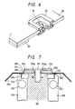
- Fig. 7 shows a sectional view of an ink jet head which is a still further embodiment of this invention.
- a cantilevered piezoelectric converter 331 is of multilayer structure with a piezoelectric material layer 331 of PZT interposed between an electrode 332 made of an Au foil and a metal layer 333 made of a foil of invar that is an alloy whose thermal expansion coefficient is substantially equal to that of PZT, and is bonded to the base 312 made of a ceramic material whose thermal expansion coefficient is substantially equal to that of PZT.
- a base 312 that is made of an isolating material has on its upper surface an electrode pattern 342 that is to be electrically connected.
- a wiring 343 of a flexible board that has a corresponding wiring pattern confronting with the electrode pattern 342 is bonded so that the wiring patterns and the electrode are in conduction.
- the electrode for maintaining each piezoelectric converter 311 at the same potential is electrically wired when the spacer 344 is bonded on the metal layer 333 surface, which is the side opposite to the electrode.
- the base 312 is arranged on a holder 315 having a built-in heater 314 for melting the ink in the head and maintaining the temperature over the melting point.
- a nozzle-formed board 316 having a plurality of nozzles 316a fabricated by subjecting Ni to an electroforming process is secured to a center frame 317 made of a stainless material whose thermal expansion coefficient is substantially equal to that of the nozzle-formed board by means of welding.
- Fig. 8 is a sectional view of the ink jet head shown in Fig. 7 when viewed from the left side of the drawing.
- the flat piezoelectric converter 311 secured to the base 312 is divided by forming grooves 341 by a dicing process.
- the forming of the grooves 341 that are as deep as to the base 312 allows a plurality of piezoelectric converters 311 that do not interfere with one another to be prepared.
- the center frame 317 has one of its ends secured to the base 312 directly by the screw 318, and the other end provided with the top ends of a V-shaped member made up of two plate springs 319 welded at one of their ends.
- the shorter one of the top ends of the V-shaped plate springs 319 is welded to a mounting plate 320 made of the same material as that of the center frame 317, and the mounting plate 320 is secured to the base 312 by the screw 318. At this time, the nozzle-formed board 316 is adjusted so that a predetermined clearance is provided with respect to the piezoelectric converter 311 by the spacer 344.
- the clearance between the piezoelectric converter 311 and the nozzle-formed board 316 must be highly accurate in order to ensure the prescribed ink jetting performance. For instance, according to the results of an experiment conducted by the inventor and his group using a PZT of 0.1 mm in thickness, such a clearance must be controlled to 5 to 40 ⁇ m ⁇ 10 ⁇ m depending on the viscosity of the ink.
- the thermal stresses will be relieved in the following manner. There is so small a difference in thermal expansion coefficient between the pair of the piezoelectric converter 311 and the base 312, and the pair of the nozzle-formed board 316 and the center frame 317, respectively that the thermal stresses to be caused will be small. More specifically, let it be supposed that the thermal expansion coefficient of the piezoelectric converter 311 using the value of PZT is 1.8E-6/°C (the term "E-6" as used herein means "10 ⁇ 6"); and that of the base 312, using the value of ceramic, is 2E-6/°C.
- the dimensional difference caused by a temperature difference of 200°C between the piezoelectric converter 311 of 40 mm in flat plate and the base 312 is as small as 1.6 ⁇ m.
- the thermal expansion coefficient of the nozzle-formed board 316 using the value of Ni is 12.8E-6/°C
- that of the center frame 317 using the value of a stainless steel is 13E-6/°C
- the dimensional difference with a temperature difference of 200°C is 1.6 ⁇ m. If the piezoelectric converter 311 and the nozzle-formed board 316 are unitized, the dimensional difference caused under the same condition is 88 ⁇ m, which is 50 times that of the case where the components whose thermal expansion coefficients are close to each other.
- the center frame 317 whose thermal expansion coefficient is large presses the base 312 so as to expand from within, resulting in deformation or breakage of either of the two.
- the center frame 317 is secured to the base 312 by interposing therebetween the screw 318 through the V-shaped plate spring 319 as shown in Fig. 8. Since the plate spring 319 is easily deformable with respect to a force in the length direction of the center frame 317, it can absorb the above-described dimensional differences caused by differences in thermal expansion coefficient.
- the plate spring 319 is rigid in directions orthogonal to the length direction of the center frame 317; i.e., the vertical direction with Fig.
- the respective nozzles 316a disposed on the nozzle-formed board 316 are arranged so that they coincide with the center of the respective piezoelectric converters 311 that are thermally expanded at an operating temperature.
- Fig. 9 shows a still further embodiment of this invention, in which the number of components is reduced by arranging a dimensional difference absorbing unit 317a inside the center frame 317.
- the operation and the like, being similar to the previous embodiment, will be omitted.
- the present invention can maintain the clearance between the nozzle-formed board and the vibrator element as accurately as required with its arrangement adapted for relieving the stress caused by a change in temperature, thereby providing the advantage of not only preventing the deformation and breakage because it causes no significant stresses to the related components but also achieving high reliability.
- the arrangement that allows relative sliding means absence of thermal stresses, and thus further provides the advantage of increasing the scope in selecting the material and thus of using highly machinable materials. Moreover, it is possible to operate at higher temperatures, thereby providing a wider choice of selecting the ink.
- the present invention it is possible to minimize the thermal stress due to changes in temperature and to absorb the dimensional difference between the materials whose thermal expansion coefficients greatly differ by the dimensional difference absorbing unit, thereby preventing deformation and breakage of the materials. Consequently, a stable performance can be achieved and a high reliability is ensured.
- the arrangement that the nozzle-formed board and the center frame are secured in the vicinity of the nozzles also provides the advantage of accurately maintaining the clearance between the piezoelectric converter and the nozzle, which is important in terms of the ink jetting performance.
Abstract
An ink jet head for a recording apparatus comprises: a nozzle-formed member (22) having a plurality of nozzle orifices; a heating member (26) for heating ink which is solid at ambient temperature to liquefy the ink; a piezoelectric converter (21) spaced apart from the nozzle-formed member for causing the liquefied ink to be loaded between the piezoelectric converter and the nozzle-formed member and for jetting the liquefied ink loaded therebetween through the nozzle-formed member; and a member (28, 25) for relatively displaceably positioning the nozzle-formed member.
Description
- This invention relates to an ink jet type recording apparatus such as a printer which forms ink images on a medium such as recording paper by melting an ink that is solid at ambient temperature (hot-melt ink) and jetting the molten, and thus liquid droplets of ink. More particularly, it is directed to an ink jet printer head for use in the ink jet type recording apparatus.
- A conventional ink jet type recording apparatus using hot-melt ink has the advantage of being compatible with many kinds of recording paper, of not causing the ink to evaporate while the apparatus is not being used, and of causing no clogging of its ink jetting nozzles. An ink jet head used in this apparatus has been constituted by a nozzle-formed member having a plurality of nozzle orifices, a heater, a piezoelectric converter, and an ink reservoir, and the nozzle-formed member has been unitized with the head forming members including the piezoelectric converter (USP 4631557, Japanese Utility Model Application (UPA) No. 41652/1981 (the term "UPA" as used herein means "Unexamined Published Application").
- The above-described conventional ink jet head has a structure in which its components having different thermal expansion coefficients are subjected to thermal stresses due to temperature variations that result from the melting of the ink. Deformations of the components caused by the thermal stress impose problems in terms of ensuring proper accuracy for stable performance and achieving undamageable structures for high reliability.
- An object of this invention is therefore to eliminate the thermal stresses caused in association with temperature variations by overcoming the above problems, and thus to achieve stable performance and high reliability.
- The foregoing object and other objects of the invention have been achieved by the features described in independent claims 1 and 6. Further advantageous features of the ink jet head in accordance with the invention are evident from the dependent claims.
- An ink jet head according to the present invention comprises a nozzle-formed member having a plurality of nozzle orifices, a piezoelectric converter, and heating means, in which a solid ink is molten by the heating mean, the molten ink is loaded between the nozzle-formed member and the piezoelectric converter, and the loaded ink is jetted by the piezoelectric converter.
- In such an ink jet head, the nozzle-formed member is supported so as to be relatively displaceable by receiving the pressing force pressed to either the piezoelectric converter or its supporting member.
- Further, in such an ink jet head, the nozzle-formed member is supported so as to be relatively displaceable by being guided by its supporting member.
- Still further, in such an ink jet head, the nozzle-formed member is firmly bonded to a supporting member whose thermal expansion coefficient is substantially equal to the nozzle-formed member, and the piezoelectric converter is firmly bonded to a supporting member whose thermal expansion coefficient is substantially equal to the piezoelectric converter.
- In the above arrangements of the present invention, the nozzle-formed member is supported so as to be displaceable relative to another member. This allows the nozzle-formed member to be expanded and contracted freely, thereby releasing it from thermal stresses. The absence of thermal stresses in the nozzle-formed member, which must be maintained at high temperatures to jet the liquid ink, contributes to ensuring high accuracy in dimensions and reducing stresses.
- Moreover, in the above arrangements of the present invention, both the nozzle-formed member and the piezoelectric converter are firmly bonded by the supporting members whose thermal expansion coefficients are equal to the supported, so that they are free from the thermal stresses which different thermal expansion coefficients cause as the temperature varies in association with the melting of the ink.
- Other features and advantages of the present invention will be apparent from the following description taken in connection with the accompanying drawings, wherein:
- Fig. 1 is a perspective view showing a printer having an ink jet head which is an embodiment of this invention;
- Fig. 2 is a sectional view of the ink jet head of the embodiment;
- Fig. 3 (a) is a perspective view showing the process of manufacturing the peripheral portions of a piezoelectric converter of the ink jet head of the embodiment;
- Fig. 3 (b) is a perspective view of a piezoelectric converter unit;
- Fig. 4 is a sectional view of an ink jet head which is a further embodiment of this invention;
- Fig. 5 is a sectional view of an ink jet head which is a still further embodiment of this invention;
- Fig. 6 is a perspective view showing a nozzle-formed board and nozzle-formed board supporting member for use in the ink jet heads according to this invention;
- Figs. 7 and 8 are sectional views of an ink jet head which is a still further embodiment of this invention; and
- Fig. 9 is a schematic plan view of an ink jet head which is a still further embodiment of this invention.
- This invention will next be described with reference to embodiments thereof.
- Fig. 1 is a perspective view of a printer showing an embodiment of this invention. In the figure, a sheet of
recording paper 10 is wound around aplaten 11 and pressed by forwardingrollers ink jet head 16 is mounted on acarriage 15 that is guided byguide shafts ink jet head 16 has a plurality of nozzles, each of which can jet ink droplets independently of one another under control; scans along the platen shaft; and selectively jet the ink droplets to form an ink image on therecording paper 10. Therecording paper 10 is transferred in a minor scanning direction that is perpendicular to the main scanning direction by the rotation of theforwarding rollers - Fig. 2 is a sectional view of an ink jet head that is the embodiment of this invention. This ink jet head comprises: a
converter unit 31 in which abase material 25, apiezoelectric converter 21, aspacer 23, and apermanent magnet 28 are fixed and unitized with awiring 27 provided. It also has aheater 26, mounted on aframe 20, for melting the ink on the head and keeping the temperature of the ink over the melting point. Theheater 26 is fixed by a bonding material. A nozzle-formedboard 22, integral with areinforcement board 30, is positioned on theconverter unit 31 and supported so as to be relatively displaceable. That is, the nozzle-formedboard 22 is pressed toward thebase 25 by the attraction of thepermanent magnet 28. Thepiezoelectric converter 21 comprises a vibrator element of multilayer structure. More specifically, the vibrator element consists of apiezoelectric material layer 35 made of PZT interposed between anelectrode layer 33 made of an Au (gold) foil and ametal layer 34 made of a Ni foil. - Fig. 3(a) and 3(b) show arrangements of the
converter unit 31 and the peripheral portions thereof, respectively, in which the same members as those shown in Fig. 2 will be designated by the same reference numbers. Fig. 3(a) shows the manufacturing process of the converter unit. Themultilayer board 40 forming vibrator element, thebase material 25, thespacer 23, and thepermanent magnet 28 are integrally bonded by a thermally resistant bonding agent or the like. Thereafter, as shown in Fig. 3(b), a plurality ofgrooves 41 are arranged by a dicing process to form thepiezoelectric converter 21 having a plurality of vibrator elements that can be driven independently of one another. The plurality of cantilevered vibrator elements, each of which is free from interference can be prepared by forming thegrooves 41 as deep as to thebase material 25. Thebase material 25 is made of an isolating body (glass, ceramic, or the like) whose upper end is provided with anelectrode pattern 43 that will be electrically connected. In order to connect to an external drive circuit, theelectrode pattern 43 on thebase material 25 is bonded to thewiring 27 of a flexible board that has a corresponding wiring pattern confronting with theelectrode pattern 43, as shown in Fig. 2. An electrode for maintaining an equal potential for eachvibrator element 21 is electrically connected when thespacer 23 is bonded to the surface of themetal layer 34 which is opposite to the side of theelectrode layer 33. - An assembling arrangement of the
converter unit 31 and its peripheral members into the head body will next be described with reference to Figs. 2 and 3. The nozzle-formedboard 22 is composed of a Ni thin board having a plurality ofnozzles 24, and constitutes a nozzle-formedboard unit 29 by being integrally bonded to thereinforcement member 30 made likewise of a Ni board and covering the periphery of the nozzle-formedboard 22. Theconverter unit 31 is positioned by a positioning pin (not shown) fixed on theframe 20 and ahole 44, and secured to theframe 20 with ascrew 32. Then, the nozzle-formedboard unit 29 is mounted on theconverter unit 31 withpins board 22 corresponding to thepins oval hole 48, so that the nozzle-formedboard unit 29 can be positioned by referencing only theother hole 49. Since nickel is a ferromagnetic material, it is attracted by thepermanent magnet 28 and thus set to a predetermined position. Nickel, with its curie temperature being as high as 350°C and its magnetic property maintained at high temperatures, does not lose its attracting force during the operation. - A further embodiment of this invention will be shown in Fig. 4. Unlike the embodiment shown in Fig. 2, the converter unit and the nozzle-formed
board 22 in this embodiment are supported so as to be relatively displaceable by receiving the pressing force of aspring 60. Since the operation and the like are the same as in the embodiment shown in Fig. 2, the descriptions thereof will be omitted. - A still further embodiment shown in Fig. 5 uses no
permanent magnet 28, unlike the embodiment of Fig. 2. In the embodiment shown in Fig. 5, abase material 25, apiezoelectric converter 21, and aspacer 23 are fixed in advance, and a nozzle-formedboard 22 and a nozzle-formed board supporting member 230 for guiding the nozzle-formedboard 22 are fixed thereon to form a unitizedconverter unit 31. - The nozzle-formed
board 22 is made of a Ni thin board having a plurality ofnozzles 24 and is guided and supported by the nozzle-formed board supporting member 230 that covers the periphery of the nozzle-formedboard 22 to constitute a nozzle-formedboard unit 29. This nozzle-formedboard 22 is made of invar. - The operation will next be described. At the printing start, electric power is supplied to the
heater 26 to liquefy theink 100 in the head by melting. In this embodiment, a solid ink whose main constituent is wax is used, and it is maintained at a predetermined temperature between 100 and 200°C with a predetermined viscosity required to satisfy a certain jetting performance. By applying a voltage between theelectrode layer 33 and themetal layer 34 formed on both sides of thevibrator element 42 through thewiring 27, thepiezoelectric material layer 35 is contracted while themetal layer 34 is not contracted, so that a bending moment is caused to displace the tip of thevibrator element 42 in the direction of its thickness. When this voltage is removed, the pressure caused by the displacement derived from the elastic restoring force of the vibrator element causes the ink to jet from thenozzles 24. - As is apparent from the above description, the unitization of the head with the member whose thermal expansion coefficient is different from that of the head itself causes a thermal stress due to a difference in temperature between ambient temperature and the head that is heated and maintained as heated during the ink jetting operation. The thermal stress will be eliminated in the following manner with the above-described construction of this embodiment. Although the
frame 20 made of aluminum has a large thermal expansion coefficient and the converter unit 31 a small thermal expansion coefficient, the relative positional deviation between the two members is very small. For instance, let it be supposed that a distance between the screw and the pin, i.e., theholes converter unit 31 should have a substantially equal thermal expansion coefficient. Thus, the material must be selected from this viewpoint. In this embodiment, thebase material 25 is made of glass or ceramic; the piezoelectric material, PZT; themetal layer 34, invar, which is a metal having a low thermal expansion coefficient; and thespacer 23 is likewise made of invar, so that the above requirement can be satisfied. As the permanent magnet, a sintered rare earth metal magnet, a ferrite magnet, or the like can be used as having a high coercive force at high temperatures and a proper thermal expansion coefficient. They may be bonded by a soft type bonding agent such as a silicon rubber. - On the other hand, the distance between the vibrator element and the nozzle-formed board must be controlled accurately to ensure a certain ink jetting performance. For instance, according to the results of the experiments conducted by the inventor and others using a vibrator element of 0.1 mm in thickness, such a distance must be controlled to 5 to 40 µm ± 10 µm depending on the viscosity of the ink. The thickness of the nozzle-formed board is 30 to 150 µm to reduce the fluid resistance to which the ink is subjected. However, the restrictions including the thickness of the nozzle-formed board, the space, and the like impose limits on the strength and dimensions of the respective components, and this does not allow the converter unit to be provided with the screw. For this reason, it is necessary to make an arrangement so that the external forces to be applied to the components can be accurately controlled and the thermal stresses can be removed in such a manner as to maintain the dimensions of the components unchanged. The nozzle-formed board, generally having to accommodate a number of very small nozzles, is subjected to restrictions in terms of the material to be used and the machining method. For instance, nickel is electroformed. In the structure of the embodiment shown in Fig. 2, the
converter unit 31 and the nozzle-formed board are attracted by a magnetic attraction that provides them with an average pressure. Relative displacements allowed to both components help relieve the stress with the relative position held by the positioning pin. With this arrangement, the distance between the nozzle-formed board and the vibrator element constituting the conversion unit can be controlled accurately as demanded to ensure a prescribed performance even in the case where the material such as nickel that has a thermal expansion coefficient different from that of the converter unit. The high bending strength provided by the reinforcement board prevents generation of buckling and warpage and thus permits smooth sliding at its boundaries. - The embodiment shown in Fig. 5 is arranged so that the nozzle-formed board is engaged with and thus guided by the nozzle-formed board supporting member and is supported so as to be relatively displaceable. Thus, their relative displacement permits stresses caused by expansion of the nozzle-formed board to be relieved. The nozzle-formed board can be assembled into the nozzle-formed board supporting member when the former is in contraction at low temperatures. Instead, the nozzle-formed board supporting member may be arranged in separate piece and unitized after the nozzle-formed board has been assembled.
- Fig. 7 shows a sectional view of an ink jet head which is a still further embodiment of this invention. A cantilevered
piezoelectric converter 331 is of multilayer structure with apiezoelectric material layer 331 of PZT interposed between anelectrode 332 made of an Au foil and ametal layer 333 made of a foil of invar that is an alloy whose thermal expansion coefficient is substantially equal to that of PZT, and is bonded to the base 312 made of a ceramic material whose thermal expansion coefficient is substantially equal to that of PZT. A base 312 that is made of an isolating material has on its upper surface anelectrode pattern 342 that is to be electrically connected. In order to connect theelectrode 332 of apiezoelectric converter 311 to an external drive circuit, awiring 343 of a flexible board that has a corresponding wiring pattern confronting with theelectrode pattern 342 is bonded so that the wiring patterns and the electrode are in conduction. The electrode for maintaining eachpiezoelectric converter 311 at the same potential is electrically wired when thespacer 344 is bonded on themetal layer 333 surface, which is the side opposite to the electrode. Further, thebase 312 is arranged on aholder 315 having a built-inheater 314 for melting the ink in the head and maintaining the temperature over the melting point. On the other hand, a nozzle-formedboard 316 having a plurality ofnozzles 316a fabricated by subjecting Ni to an electroforming process is secured to acenter frame 317 made of a stainless material whose thermal expansion coefficient is substantially equal to that of the nozzle-formed board by means of welding. - Fig. 8 is a sectional view of the ink jet head shown in Fig. 7 when viewed from the left side of the drawing. In order to form a plurality of
piezoelectric converters 311, each being driven independently, the flatpiezoelectric converter 311 secured to thebase 312 is divided by forminggrooves 341 by a dicing process. The forming of thegrooves 341 that are as deep as to thebase 312 allows a plurality ofpiezoelectric converters 311 that do not interfere with one another to be prepared. Thecenter frame 317 has one of its ends secured to the base 312 directly by thescrew 318, and the other end provided with the top ends of a V-shaped member made up of two plate springs 319 welded at one of their ends. The shorter one of the top ends of the V-shaped plate springs 319 is welded to a mounting plate 320 made of the same material as that of thecenter frame 317, and the mounting plate 320 is secured to thebase 312 by thescrew 318. At this time, the nozzle-formedboard 316 is adjusted so that a predetermined clearance is provided with respect to thepiezoelectric converter 311 by thespacer 344. - The operation will next be described. At the printing start in Fig. 7, electric power is supplied to the
heater 314 and theink 351 within the head is liquefied by melting. In this embodiment, a solid ink whose main constituent is wax is used, and it is maintained at a predetermined temperature between 100 and 200°C with a predetermined viscosity required to satisfy a certain jetting performance. By applying a voltage between theelectrode layer 332 and themetal layer 333 formed on both sides of thepiezoelectric converter 311 through thewiring 343, thepiezoelectric material layer 331 is contracted while themetal layer 333 is not contracted, so that a bending moment is caused to displace the tip of thepiezoelectric converter 311 in the direction of its thickness (the downward direction in the figure). When this voltage is removed, the pressure caused by the displacement derived from the elastic restoring force of thepiezoelectric converter 311 causes the ink to jet from thenozzles 316a of the nozzle-formedboard 316. This operation is repeated in accordance with a printing signal to perform a desired printing operation. - As is apparent from the above description, thermal stresses are caused during the ink jetting operation if the head is unitized with a member whose thermal expansion coefficient is different from itself; because as the head is heated to a high temperature, there exists a temperature difference between the high temperature and the ambient temperature. The components are more likely to be deformed or broken with larger temperature differences. Particularly, the clearance between the
piezoelectric converter 311 and the nozzle-formedboard 316 must be highly accurate in order to ensure the prescribed ink jetting performance. For instance, according to the results of an experiment conducted by the inventor and his group using a PZT of 0.1 mm in thickness, such a clearance must be controlled to 5 to 40 µm ± 10 µm depending on the viscosity of the ink. With the arrangement of this embodiment, the thermal stresses will be relieved in the following manner. There is so small a difference in thermal expansion coefficient between the pair of thepiezoelectric converter 311 and thebase 312, and the pair of the nozzle-formedboard 316 and thecenter frame 317, respectively that the thermal stresses to be caused will be small. More specifically, let it be supposed that the thermal expansion coefficient of thepiezoelectric converter 311 using the value of PZT is 1.8E-6/°C (the term "E-6" as used herein means "10⁻⁶"); and that of thebase 312, using the value of ceramic, is 2E-6/°C. Then, the dimensional difference caused by a temperature difference of 200°C between thepiezoelectric converter 311 of 40 mm in flat plate and thebase 312 is as small as 1.6 µm. On the other hand, if the thermal expansion coefficient of the nozzle-formedboard 316 using the value of Ni is 12.8E-6/°C, and that of thecenter frame 317 using the value of a stainless steel is 13E-6/°C, then, the dimensional difference with a temperature difference of 200°C is 1.6 µm. If thepiezoelectric converter 311 and the nozzle-formedboard 316 are unitized, the dimensional difference caused under the same condition is 88 µm, which is 50 times that of the case where the components whose thermal expansion coefficients are close to each other. Such a dimensional difference directly affects the respective components as a thermal stress. That is, thecenter frame 317 whose thermal expansion coefficient is large presses the base 312 so as to expand from within, resulting in deformation or breakage of either of the two. In order to absorb this dimensional difference, thecenter frame 317 is secured to thebase 312 by interposing therebetween thescrew 318 through the V-shapedplate spring 319 as shown in Fig. 8. Since theplate spring 319 is easily deformable with respect to a force in the length direction of thecenter frame 317, it can absorb the above-described dimensional differences caused by differences in thermal expansion coefficient. However, theplate spring 319 is rigid in directions orthogonal to the length direction of thecenter frame 317; i.e., the vertical direction with Fig. 8 viewed from the front and the direction of going through the sheet on which Fig. 8 is drawn. Therefore, the clearance between thepiezoelectric converter 311 and the nozle-formedboard 316 can be maintained accurately. Therespective nozzles 316a disposed on the nozzle-formedboard 316 are arranged so that they coincide with the center of the respectivepiezoelectric converters 311 that are thermally expanded at an operating temperature. - Fig. 9 shows a still further embodiment of this invention, in which the number of components is reduced by arranging a dimensional
difference absorbing unit 317a inside thecenter frame 317. The operation and the like, being similar to the previous embodiment, will be omitted. - As described in the foregoing pages, the present invention can maintain the clearance between the nozzle-formed board and the vibrator element as accurately as required with its arrangement adapted for relieving the stress caused by a change in temperature, thereby providing the advantage of not only preventing the deformation and breakage because it causes no significant stresses to the related components but also achieving high reliability.
- The arrangement that allows relative sliding means absence of thermal stresses, and thus further provides the advantage of increasing the scope in selecting the material and thus of using highly machinable materials. Moreover, it is possible to operate at higher temperatures, thereby providing a wider choice of selecting the ink.
- Furthermore, according to the present invention, it is possible to minimize the thermal stress due to changes in temperature and to absorb the dimensional difference between the materials whose thermal expansion coefficients greatly differ by the dimensional difference absorbing unit, thereby preventing deformation and breakage of the materials. Consequently, a stable performance can be achieved and a high reliability is ensured.
- The arrangement that the nozzle-formed board and the center frame are secured in the vicinity of the nozzles also provides the advantage of accurately maintaining the clearance between the piezoelectric converter and the nozzle, which is important in terms of the ink jetting performance.
Claims (6)
1. An ink jet head for a recording apparatus, comprising:
a nozzle-formed member having a plurality of nozzle orifices;
heating means for heating ink which is solid at ambient temperature to liquefy the ink;
a piezoelectric converter spaced apart from said nozzle-formed member for causing the liqueified ink to be loaded between said piezoelectric converter and said nozzle-formed member and for jetting the liquefied ink loaded therebetween through said nozzle-formed member; and
means for relatively displaceably positioning said nozzle-formed member.
2. An ink jet head as claimed in Claim 1, wherein said positioning means directly or indirectly applies a pressing force to said nozzle-formed member.
3. An ink jet head as claimed in Claim 2, wherein said positioning means comprises a permanent magnet, and said nozzle-formed member is formed of a ferromagnetic material.
4. An ink jet head as claimed in Claim 2, wherein said positioning means comprises a spring.
5. An ink jet head as claimed in Claim 1, wherein said positioning means comprises a member for relatively displacebly supporting said nozzle-formed member with guidance.
6. An ink jet head for a recording apparatus, comprising:
a nozzle-formed member having a plurality of nozzle orifices;
heating means for heating ink which is solid at ambient temperature to liquefy the ink;
a piezoelectric converter spaced apart from said nozzle-formed member for causing the liqueified ink to be loaded between said piezoelectric converter and said nozzle-formed member and for jetting the liquefied ink loaded therebetween through said nozzle-formed member;
a first supporting member to which said nozzle-formed member is firmly bonded, said first supporting member having a thermal expansion coefficient substantially equal to that of said nozzle-formed member; and
a second supporting member to which said piezoelectric converter is firmly bonded, said second supporting member having a thermal expansion coefficient substantially equal to that of said piezoelectric converter.
Applications Claiming Priority (6)
| Application Number | Priority Date | Filing Date | Title |
|---|---|---|---|
| JP99104/89 | 1989-04-19 | ||
| JP9910389A JPH02277640A (en) | 1989-04-19 | 1989-04-19 | Ink jet head |
| JP99103/89 | 1989-04-19 | ||
| JP9910489A JPH02277641A (en) | 1989-04-19 | 1989-04-19 | Ink jet head |
| JP13301089A JPH03255A (en) | 1989-05-26 | 1989-05-26 | Ink jet head |
| JP133010/89 | 1989-05-26 |
Publications (1)
| Publication Number | Publication Date |
|---|---|
| EP0398031A1 true EP0398031A1 (en) | 1990-11-22 |
Family
ID=27308865
Family Applications (1)
| Application Number | Title | Priority Date | Filing Date |
|---|---|---|---|
| EP90107376A Withdrawn EP0398031A1 (en) | 1989-04-19 | 1990-04-18 | Ink jet head |
Country Status (2)
| Country | Link |
|---|---|
| US (1) | US5113204A (en) |
| EP (1) | EP0398031A1 (en) |
Cited By (67)
| Publication number | Priority date | Publication date | Assignee | Title |
|---|---|---|---|---|
| EP0488113A1 (en) * | 1990-11-28 | 1992-06-03 | Matsushita Electric Industrial Co., Ltd. | Ink-jet recording apparatus |
| EP0713773A3 (en) * | 1994-11-24 | 1997-04-16 | Pelikan Produktions Ag | Microdroplets generator in particular for ink jet printers |
| EP0999934A1 (en) * | 1997-07-15 | 2000-05-17 | Silver Brook Research Pty, Ltd | A thermally actuated ink jet |
| SG93895A1 (en) * | 1999-09-29 | 2003-01-21 | Ibm | Piezoelectric sensor, method for fixing the same, actuator, disk unit, and method for checking connections |
| US6746105B2 (en) | 1997-07-15 | 2004-06-08 | Silverbrook Research Pty. Ltd. | Thermally actuated ink jet printing mechanism having a series of thermal actuator units |
| US6776476B2 (en) | 1997-07-15 | 2004-08-17 | Silverbrook Research Pty Ltd. | Ink jet printhead chip with active and passive nozzle chamber structures |
| US6783217B2 (en) | 1997-07-15 | 2004-08-31 | Silverbrook Research Pty Ltd | Micro-electromechanical valve assembly |
| US6786570B2 (en) | 1997-07-15 | 2004-09-07 | Silverbrook Research Pty Ltd | Ink supply arrangement for a printing mechanism of a wide format pagewidth inkjet printer |
| US6824251B2 (en) | 1997-07-15 | 2004-11-30 | Silverbrook Research Pty Ltd | Micro-electromechanical assembly that incorporates a covering formation for a micro-electromechanical device |
| US6834939B2 (en) | 2002-11-23 | 2004-12-28 | Silverbrook Research Pty Ltd | Micro-electromechanical device that incorporates covering formations for actuators of the device |
| US6880918B2 (en) | 1997-07-15 | 2005-04-19 | Silverbrook Research Pty Ltd | Micro-electromechanical device that incorporates a motion-transmitting structure |
| US6880914B2 (en) | 1997-07-15 | 2005-04-19 | Silverbrook Research Pty Ltd | Inkjet pagewidth printer for high volume pagewidth printing |
| US6886917B2 (en) | 1998-06-09 | 2005-05-03 | Silverbrook Research Pty Ltd | Inkjet printhead nozzle with ribbed wall actuator |
| US6886918B2 (en) | 1998-06-09 | 2005-05-03 | Silverbrook Research Pty Ltd | Ink jet printhead with moveable ejection nozzles |
| US6916082B2 (en) | 1997-07-15 | 2005-07-12 | Silverbrook Research Pty Ltd | Printing mechanism for a wide format pagewidth inkjet printer |
| US6918707B2 (en) | 1997-07-15 | 2005-07-19 | Silverbrook Research Pty Ltd | Keyboard printer print media transport assembly |
| US6927786B2 (en) | 1997-07-15 | 2005-08-09 | Silverbrook Research Pty Ltd | Ink jet nozzle with thermally operable linear expansion actuation mechanism |
| US6929352B2 (en) | 1997-07-15 | 2005-08-16 | Silverbrook Research Pty Ltd | Inkjet printhead chip for use with a pulsating pressure ink supply |
| US6932459B2 (en) | 1997-07-15 | 2005-08-23 | Silverbrook Research Pty Ltd | Ink jet printhead |
| US6935724B2 (en) | 1997-07-15 | 2005-08-30 | Silverbrook Research Pty Ltd | Ink jet nozzle having actuator with anchor positioned between nozzle chamber and actuator connection point |
| US6976751B2 (en) | 1997-07-15 | 2005-12-20 | Silverbrook Research Pty Ltd | Motion transmitting structure |
| US6986613B2 (en) | 1997-07-15 | 2006-01-17 | Silverbrook Research Pty Ltd | Keyboard |
| US7004566B2 (en) | 1997-07-15 | 2006-02-28 | Silverbrook Research Pty Ltd | Inkjet printhead chip that incorporates micro-mechanical lever mechanisms |
| US7008046B2 (en) | 1997-07-15 | 2006-03-07 | Silverbrook Research Pty Ltd | Micro-electromechanical liquid ejection device |
| US7008041B2 (en) | 1997-07-15 | 2006-03-07 | Silverbrook Research Pty Ltd | Printing mechanism having elongate modular structure |
| US7022250B2 (en) | 1997-07-15 | 2006-04-04 | Silverbrook Research Pty Ltd | Method of fabricating an ink jet printhead chip with differential expansion actuators |
| US7040738B2 (en) | 1997-07-15 | 2006-05-09 | Silverbrook Research Pty Ltd | Printhead chip that incorporates micro-mechanical translating mechanisms |
| US7044584B2 (en) | 1997-07-15 | 2006-05-16 | Silverbrook Research Pty Ltd | Wide format pagewidth inkjet printer |
| US7066574B2 (en) | 1997-07-15 | 2006-06-27 | Silverbrook Research Pty Ltd | Micro-electromechanical device having a laminated thermal bend actuator |
| US7111924B2 (en) | 1998-10-16 | 2006-09-26 | Silverbrook Research Pty Ltd | Inkjet printhead having thermal bend actuator heating element electrically isolated from nozzle chamber ink |
| US7131715B2 (en) | 1997-07-15 | 2006-11-07 | Silverbrook Research Pty Ltd | Printhead chip that incorporates micro-mechanical lever mechanisms |
| US7144519B2 (en) | 1998-10-16 | 2006-12-05 | Silverbrook Research Pty Ltd | Method of fabricating an inkjet printhead chip having laminated actuators |
| US7147302B2 (en) | 1997-07-15 | 2006-12-12 | Silverbrook Researh Pty Ltd | Nozzle assembly |
| US7147305B2 (en) | 1997-07-15 | 2006-12-12 | Silverbrook Research Pty Ltd | Printer formed from integrated circuit printhead |
| US7175260B2 (en) | 2002-06-28 | 2007-02-13 | Silverbrook Research Pty Ltd | Ink jet nozzle arrangement configuration |
| US7195339B2 (en) | 1997-07-15 | 2007-03-27 | Silverbrook Research Pty Ltd | Ink jet nozzle assembly with a thermal bend actuator |
| US7207654B2 (en) | 1997-07-15 | 2007-04-24 | Silverbrook Research Pty Ltd | Ink jet with narrow chamber |
| US7240992B2 (en) | 1997-07-15 | 2007-07-10 | Silverbrook Research Pty Ltd | Ink jet printhead incorporating a plurality of nozzle arrangement having backflow prevention mechanisms |
| US7246884B2 (en) | 1997-07-15 | 2007-07-24 | Silverbrook Research Pty Ltd | Inkjet printhead having enclosed inkjet actuators |
| US7246883B2 (en) | 1997-07-15 | 2007-07-24 | Silverbrook Research Pty Ltd | Motion transmitting structure for a nozzle arrangement of a printhead chip for an inkjet printhead |
| US7252366B2 (en) | 1997-07-15 | 2007-08-07 | Silverbrook Research Pty Ltd | Inkjet printhead with high nozzle area density |
| US7267424B2 (en) | 1997-07-15 | 2007-09-11 | Silverbrook Research Pty Ltd | Wide format pagewidth printer |
| US7278711B2 (en) | 1997-07-15 | 2007-10-09 | Silverbrook Research Pty Ltd | Nozzle arrangement incorporating a lever based ink displacement mechanism |
| US7287836B2 (en) | 1997-07-15 | 2007-10-30 | Sil;Verbrook Research Pty Ltd | Ink jet printhead with circular cross section chamber |
| US7303254B2 (en) | 1997-07-15 | 2007-12-04 | Silverbrook Research Pty Ltd | Print assembly for a wide format pagewidth printer |
| US7334873B2 (en) | 2002-04-12 | 2008-02-26 | Silverbrook Research Pty Ltd | Discrete air and nozzle chambers in a printhead chip for an inkjet printhead |
| US7360872B2 (en) | 1997-07-15 | 2008-04-22 | Silverbrook Research Pty Ltd | Inkjet printhead chip with nozzle assemblies incorporating fluidic seals |
| US7381340B2 (en) | 1997-07-15 | 2008-06-03 | Silverbrook Research Pty Ltd | Ink jet printhead that incorporates an etch stop layer |
| US7401901B2 (en) | 1997-07-15 | 2008-07-22 | Silverbrook Research Pty Ltd | Inkjet printhead having nozzle plate supported by encapsulated photoresist |
| US7407269B2 (en) | 2002-06-28 | 2008-08-05 | Silverbrook Research Pty Ltd | Ink jet nozzle assembly including displaceable ink pusher |
| US7431446B2 (en) | 1997-07-15 | 2008-10-07 | Silverbrook Research Pty Ltd | Web printing system having media cartridge carousel |
| US7434915B2 (en) | 1997-07-15 | 2008-10-14 | Silverbrook Research Pty Ltd | Inkjet printhead chip with a side-by-side nozzle arrangement layout |
| US7461924B2 (en) | 1997-07-15 | 2008-12-09 | Silverbrook Research Pty Ltd | Printhead having inkjet actuators with contractible chambers |
| US7465030B2 (en) | 1997-07-15 | 2008-12-16 | Silverbrook Research Pty Ltd | Nozzle arrangement with a magnetic field generator |
| US7468139B2 (en) | 1997-07-15 | 2008-12-23 | Silverbrook Research Pty Ltd | Method of depositing heater material over a photoresist scaffold |
| US7524026B2 (en) | 1997-07-15 | 2009-04-28 | Silverbrook Research Pty Ltd | Nozzle assembly with heat deflected actuator |
| US7556356B1 (en) | 1997-07-15 | 2009-07-07 | Silverbrook Research Pty Ltd | Inkjet printhead integrated circuit with ink spread prevention |
| US7571988B2 (en) | 2000-05-23 | 2009-08-11 | Silverbrook Research Pty Ltd | Variable-volume nozzle arrangement |
| US7753463B2 (en) | 1997-07-15 | 2010-07-13 | Silverbrook Research Pty Ltd | Processing of images for high volume pagewidth printing |
| US7758142B2 (en) | 2002-04-12 | 2010-07-20 | Silverbrook Research Pty Ltd | High volume pagewidth printing |
| US7784902B2 (en) | 1997-07-15 | 2010-08-31 | Silverbrook Research Pty Ltd | Printhead integrated circuit with more than 10000 nozzles |
| US7802871B2 (en) | 1997-07-15 | 2010-09-28 | Silverbrook Research Pty Ltd | Ink jet printhead with amorphous ceramic chamber |
| US7854500B2 (en) | 1998-11-09 | 2010-12-21 | Silverbrook Research Pty Ltd | Tamper proof print cartridge for a video game console |
| US7891767B2 (en) | 1997-07-15 | 2011-02-22 | Silverbrook Research Pty Ltd | Modular self-capping wide format print assembly |
| US7967418B2 (en) | 1997-07-15 | 2011-06-28 | Silverbrook Research Pty Ltd | Printhead with nozzles having individual supply passages extending into substrate |
| US8029101B2 (en) | 1997-07-15 | 2011-10-04 | Silverbrook Research Pty Ltd | Ink ejection mechanism with thermal actuator coil |
| US8109611B2 (en) | 2002-04-26 | 2012-02-07 | Silverbrook Research Pty Ltd | Translation to rotation conversion in an inkjet printhead |
Families Citing this family (18)
| Publication number | Priority date | Publication date | Assignee | Title |
|---|---|---|---|---|
| US5506608A (en) * | 1992-04-02 | 1996-04-09 | Hewlett-Packard Company | Print cartridge body and nozzle member having similar coefficient of thermal expansion |
| US5537133A (en) * | 1992-04-02 | 1996-07-16 | Hewlett-Packard Company | Restraining element for a print cartridge body to reduce thermally induced stress |
| JP3374862B2 (en) * | 1992-06-12 | 2003-02-10 | セイコーエプソン株式会社 | Ink jet recording device |
| JP3178945B2 (en) * | 1992-08-25 | 2001-06-25 | 日本碍子株式会社 | Inkjet print head |
| US7527357B2 (en) | 1997-07-15 | 2009-05-05 | Silverbrook Research Pty Ltd | Inkjet nozzle array with individual feed channel for each nozzle |
| US20100277531A1 (en) * | 1997-07-15 | 2010-11-04 | Silverbrook Research Pty Ltd | Printer having processor for high volume printing |
| US7410243B2 (en) * | 1997-07-15 | 2008-08-12 | Silverbrook Research Pty Ltd | Inkjet nozzle with resiliently biased ejection actuator |
| US6449831B1 (en) | 1998-06-19 | 2002-09-17 | Lexmark International, Inc | Process for making a heater chip module |
| US6039439A (en) * | 1998-06-19 | 2000-03-21 | Lexmark International, Inc. | Ink jet heater chip module |
| EP1121249B1 (en) | 1998-10-16 | 2007-07-25 | Silverbrook Research Pty. Limited | Process of forming a nozzle for an inkjet printhead |
| US6427597B1 (en) | 2000-01-27 | 2002-08-06 | Patrice M. Aurenty | Method of controlling image resolution on a substrate |
| US6526658B1 (en) | 2000-05-23 | 2003-03-04 | Silverbrook Research Pty Ltd | Method of manufacture of an ink jet printhead having a moving nozzle with an externally arranged actuator |
| AU4731400A (en) * | 2000-05-24 | 2001-12-03 | Silverbrook Res Pty Ltd | Method of manufacture of an ink jet printhead having a moving nozzle with an externally arranged actuator |
| US7232207B2 (en) * | 2002-12-27 | 2007-06-19 | Konica Minolta Holdings, Inc. | Ink jet head |
| CN1574214A (en) * | 2003-06-03 | 2005-02-02 | 国际商业机器公司 | Melt-based patterning for electronic devices |
| JP2006256265A (en) * | 2005-03-18 | 2006-09-28 | Fuji Xerox Co Ltd | Liquid droplet discharge apparatus |
| US7934092B2 (en) * | 2006-07-10 | 2011-04-26 | Silverbrook Research Pty Ltd | Electronic device having improved security |
| US8523328B2 (en) * | 2011-04-19 | 2013-09-03 | Eastman Kodak Company | Flow-through liquid ejection using compliant membrane transducer |
Citations (4)
| Publication number | Priority date | Publication date | Assignee | Title |
|---|---|---|---|---|
| EP0067889A1 (en) * | 1980-12-30 | 1982-12-29 | Fujitsu Limited | Ink jet printing head |
| US4459601A (en) * | 1981-01-30 | 1984-07-10 | Exxon Research And Engineering Co. | Ink jet method and apparatus |
| US4631557A (en) * | 1984-10-15 | 1986-12-23 | Exxon Printing Systems, Inc. | Ink jet employing phase change ink and method of operation |
| EP0338590A2 (en) * | 1988-04-22 | 1989-10-25 | Seiko Epson Corporation | Ink jet type recording apparatus and method |
Family Cites Families (6)
| Publication number | Priority date | Publication date | Assignee | Title |
|---|---|---|---|---|
| SE378029B (en) * | 1973-04-25 | 1975-08-11 | Original Odhner Ab | |
| GB1462193A (en) * | 1973-06-13 | 1977-01-19 | Ici Ltd | Pattern printing apparatus |
| US4158847A (en) * | 1975-09-09 | 1979-06-19 | Siemens Aktiengesellschaft | Piezoelectric operated printer head for ink-operated mosaic printer units |
| US4243995A (en) * | 1979-06-01 | 1981-01-06 | Xerox Corporation | Encapsulated piezoelectric pressure pulse drop ejector apparatus |
| US4779099A (en) * | 1987-02-24 | 1988-10-18 | Dataproducts Corporation | Clamp for and method of fabricating a multi-layer ink jet apparatus |
| US4998120A (en) * | 1988-04-06 | 1991-03-05 | Seiko Epson Corporation | Hot melt ink jet printing apparatus |
-
1990
- 1990-04-18 EP EP90107376A patent/EP0398031A1/en not_active Withdrawn
- 1990-04-19 US US07/511,259 patent/US5113204A/en not_active Expired - Fee Related
Patent Citations (5)
| Publication number | Priority date | Publication date | Assignee | Title |
|---|---|---|---|---|
| EP0067889A1 (en) * | 1980-12-30 | 1982-12-29 | Fujitsu Limited | Ink jet printing head |
| US4459601A (en) * | 1981-01-30 | 1984-07-10 | Exxon Research And Engineering Co. | Ink jet method and apparatus |
| US4631557A (en) * | 1984-10-15 | 1986-12-23 | Exxon Printing Systems, Inc. | Ink jet employing phase change ink and method of operation |
| US4631557B1 (en) * | 1984-10-15 | 1997-12-16 | Data Products Corp | Ink jet employing phase change ink and method of operation |
| EP0338590A2 (en) * | 1988-04-22 | 1989-10-25 | Seiko Epson Corporation | Ink jet type recording apparatus and method |
Non-Patent Citations (1)
| Title |
|---|
| PATENT ABSTRACTS OF JAPAN * |
Cited By (257)
| Publication number | Priority date | Publication date | Assignee | Title |
|---|---|---|---|---|
| EP0488113A1 (en) * | 1990-11-28 | 1992-06-03 | Matsushita Electric Industrial Co., Ltd. | Ink-jet recording apparatus |
| US5278583A (en) * | 1990-11-28 | 1994-01-11 | Matsushita Electric Industrial Co., Ltd. | Ink-jet recording apparatus |
| EP0713773A3 (en) * | 1994-11-24 | 1997-04-16 | Pelikan Produktions Ag | Microdroplets generator in particular for ink jet printers |
| US5739832A (en) * | 1994-11-24 | 1998-04-14 | Pelikan Produktions Ag | Droplet generator for generating micro-drops, specifically for an ink-jet printer |
| US7914118B2 (en) | 1997-07-15 | 2011-03-29 | Silverbrook Research Pty Ltd | Integrated circuit (IC) incorporating rows of proximal ink ejection ports |
| US7275811B2 (en) | 1997-07-15 | 2007-10-02 | Silverbrook Research Pty Ltd | High nozzle density inkjet printhead |
| US8419165B2 (en) | 1997-07-15 | 2013-04-16 | Zamtec Ltd | Printhead module for wide format pagewidth inkjet printer |
| US8408679B2 (en) | 1997-07-15 | 2013-04-02 | Zamtec Ltd | Printhead having CMOS drive circuitry |
| US6746105B2 (en) | 1997-07-15 | 2004-06-08 | Silverbrook Research Pty. Ltd. | Thermally actuated ink jet printing mechanism having a series of thermal actuator units |
| US6776476B2 (en) | 1997-07-15 | 2004-08-17 | Silverbrook Research Pty Ltd. | Ink jet printhead chip with active and passive nozzle chamber structures |
| US6783217B2 (en) | 1997-07-15 | 2004-08-31 | Silverbrook Research Pty Ltd | Micro-electromechanical valve assembly |
| US6786570B2 (en) | 1997-07-15 | 2004-09-07 | Silverbrook Research Pty Ltd | Ink supply arrangement for a printing mechanism of a wide format pagewidth inkjet printer |
| US6824251B2 (en) | 1997-07-15 | 2004-11-30 | Silverbrook Research Pty Ltd | Micro-electromechanical assembly that incorporates a covering formation for a micro-electromechanical device |
| US8287105B2 (en) | 1997-07-15 | 2012-10-16 | Zamtec Limited | Nozzle arrangement for an inkjet printhead having an ink ejecting roof structure |
| US6840600B2 (en) | 1997-07-15 | 2005-01-11 | Silverbrook Research Pty Ltd | Fluid ejection device that incorporates covering formations for actuators of the fluid ejection device |
| US6848780B2 (en) | 1997-07-15 | 2005-02-01 | Sivlerbrook Research Pty Ltd | Printing mechanism for a wide format pagewidth inkjet printer |
| US6880918B2 (en) | 1997-07-15 | 2005-04-19 | Silverbrook Research Pty Ltd | Micro-electromechanical device that incorporates a motion-transmitting structure |
| US6880914B2 (en) | 1997-07-15 | 2005-04-19 | Silverbrook Research Pty Ltd | Inkjet pagewidth printer for high volume pagewidth printing |
| US8123336B2 (en) | 1997-07-15 | 2012-02-28 | Silverbrook Research Pty Ltd | Printhead micro-electromechanical nozzle arrangement with motion-transmitting structure |
| US8113629B2 (en) | 1997-07-15 | 2012-02-14 | Silverbrook Research Pty Ltd. | Inkjet printhead integrated circuit incorporating fulcrum assisted ink ejection actuator |
| US6916082B2 (en) | 1997-07-15 | 2005-07-12 | Silverbrook Research Pty Ltd | Printing mechanism for a wide format pagewidth inkjet printer |
| US6918707B2 (en) | 1997-07-15 | 2005-07-19 | Silverbrook Research Pty Ltd | Keyboard printer print media transport assembly |
| US6921221B2 (en) | 1997-07-15 | 2005-07-26 | Silverbrook Research Pty Ltd | Combination keyboard and printer apparatus |
| US6923583B2 (en) | 1997-07-15 | 2005-08-02 | Silverbrook Research Pty Ltd | Computer Keyboard with integral printer |
| US6927786B2 (en) | 1997-07-15 | 2005-08-09 | Silverbrook Research Pty Ltd | Ink jet nozzle with thermally operable linear expansion actuation mechanism |
| US6929352B2 (en) | 1997-07-15 | 2005-08-16 | Silverbrook Research Pty Ltd | Inkjet printhead chip for use with a pulsating pressure ink supply |
| US6932459B2 (en) | 1997-07-15 | 2005-08-23 | Silverbrook Research Pty Ltd | Ink jet printhead |
| US6935724B2 (en) | 1997-07-15 | 2005-08-30 | Silverbrook Research Pty Ltd | Ink jet nozzle having actuator with anchor positioned between nozzle chamber and actuator connection point |
| US6948799B2 (en) | 1997-07-15 | 2005-09-27 | Silverbrook Research Pty Ltd | Micro-electromechanical fluid ejecting device that incorporates a covering formation for a micro-electromechanical actuator |
| US6953295B2 (en) | 1997-07-15 | 2005-10-11 | Silverbrook Research Pty Ltd | Small footprint computer system |
| US8083326B2 (en) | 1997-07-15 | 2011-12-27 | Silverbrook Research Pty Ltd | Nozzle arrangement with an actuator having iris vanes |
| US8075104B2 (en) | 1997-07-15 | 2011-12-13 | Sliverbrook Research Pty Ltd | Printhead nozzle having heater of higher resistance than contacts |
| US7216957B2 (en) | 1997-07-15 | 2007-05-15 | Silverbrook Research Pty Ltd | Micro-electromechanical ink ejection mechanism that incorporates lever actuation |
| US6976751B2 (en) | 1997-07-15 | 2005-12-20 | Silverbrook Research Pty Ltd | Motion transmitting structure |
| US8029107B2 (en) | 1997-07-15 | 2011-10-04 | Silverbrook Research Pty Ltd | Printhead with double omega-shaped heater elements |
| US8029101B2 (en) | 1997-07-15 | 2011-10-04 | Silverbrook Research Pty Ltd | Ink ejection mechanism with thermal actuator coil |
| US6986613B2 (en) | 1997-07-15 | 2006-01-17 | Silverbrook Research Pty Ltd | Keyboard |
| US6988788B2 (en) | 1997-07-15 | 2006-01-24 | Silverbrook Research Pty Ltd | Ink jet printhead chip with planar actuators |
| US6988841B2 (en) | 1997-07-15 | 2006-01-24 | Silverbrook Research Pty Ltd. | Pagewidth printer that includes a computer-connectable keyboard |
| US6994420B2 (en) | 1997-07-15 | 2006-02-07 | Silverbrook Research Pty Ltd | Print assembly for a wide format pagewidth inkjet printer, having a plurality of printhead chips |
| US7004566B2 (en) | 1997-07-15 | 2006-02-28 | Silverbrook Research Pty Ltd | Inkjet printhead chip that incorporates micro-mechanical lever mechanisms |
| US7008046B2 (en) | 1997-07-15 | 2006-03-07 | Silverbrook Research Pty Ltd | Micro-electromechanical liquid ejection device |
| US7008041B2 (en) | 1997-07-15 | 2006-03-07 | Silverbrook Research Pty Ltd | Printing mechanism having elongate modular structure |
| US7011390B2 (en) | 1997-07-15 | 2006-03-14 | Silverbrook Research Pty Ltd | Printing mechanism having wide format printing zone |
| US7022250B2 (en) | 1997-07-15 | 2006-04-04 | Silverbrook Research Pty Ltd | Method of fabricating an ink jet printhead chip with differential expansion actuators |
| US7032998B2 (en) | 1997-07-15 | 2006-04-25 | Silverbrook Research Pty Ltd | Ink jet printhead chip that incorporates through-wafer ink ejection mechanisms |
| US7040738B2 (en) | 1997-07-15 | 2006-05-09 | Silverbrook Research Pty Ltd | Printhead chip that incorporates micro-mechanical translating mechanisms |
| US7044584B2 (en) | 1997-07-15 | 2006-05-16 | Silverbrook Research Pty Ltd | Wide format pagewidth inkjet printer |
| US7055933B2 (en) | 1997-07-15 | 2006-06-06 | Silverbrook Research Pty Ltd | MEMS device having formations for covering actuators of the device |
| US7055935B2 (en) | 1997-07-15 | 2006-06-06 | Silverbrook Research Pty Ltd | Ink ejection devices within an inkjet printer |
| US7055934B2 (en) | 1997-07-15 | 2006-06-06 | Silverbrook Research Pty Ltd | Inkjet nozzle comprising a motion-transmitting structure |
| US7066578B2 (en) | 1997-07-15 | 2006-06-27 | Silverbrook Research Pty Ltd | Inkjet printhead having compact inkjet nozzles |
| US7067067B2 (en) | 1997-07-15 | 2006-06-27 | Silverbrook Research Pty Ltd | Method of fabricating an ink jet printhead chip with active and passive nozzle chamber structures |
| US7066574B2 (en) | 1997-07-15 | 2006-06-27 | Silverbrook Research Pty Ltd | Micro-electromechanical device having a laminated thermal bend actuator |
| US7077588B2 (en) | 1997-07-15 | 2006-07-18 | Silverbrook Research Pty Ltd | Printer and keyboard combination |
| US7083263B2 (en) | 1997-07-15 | 2006-08-01 | Silverbrook Research Pty Ltd | Micro-electromechanical fluid ejection device with actuator guide formations |
| US7083264B2 (en) | 1997-07-15 | 2006-08-01 | Silverbrook Research Pty Ltd | Micro-electromechanical liquid ejection device with motion amplification |
| US7083261B2 (en) | 1997-07-15 | 2006-08-01 | Silverbrook Research Pty Ltd | Printer incorporating a microelectromechanical printhead |
| US7086709B2 (en) | 1997-07-15 | 2006-08-08 | Silverbrook Research Pty Ltd | Print engine controller for high volume pagewidth printing |
| US8029102B2 (en) | 1997-07-15 | 2011-10-04 | Silverbrook Research Pty Ltd | Printhead having relatively dimensioned ejection ports and arms |
| US8025366B2 (en) | 1997-07-15 | 2011-09-27 | Silverbrook Research Pty Ltd | Inkjet printhead with nozzle layer defining etchant holes |
| US7097285B2 (en) | 1997-07-15 | 2006-08-29 | Silverbrook Research Pty Ltd | Printhead chip incorporating electro-magnetically operable ink ejection mechanisms |
| US7101023B2 (en) | 1997-07-15 | 2006-09-05 | Silverbrook Research Pty Ltd | Inkjet printhead having multiple-sectioned nozzle actuators |
| US8020970B2 (en) | 1997-07-15 | 2011-09-20 | Silverbrook Research Pty Ltd | Printhead nozzle arrangements with magnetic paddle actuators |
| US7980667B2 (en) | 1997-07-15 | 2011-07-19 | Silverbrook Research Pty Ltd | Nozzle arrangement with pivotal wall coupled to thermal expansion actuator |
| EP0999934A1 (en) * | 1997-07-15 | 2000-05-17 | Silver Brook Research Pty, Ltd | A thermally actuated ink jet |
| US7131715B2 (en) | 1997-07-15 | 2006-11-07 | Silverbrook Research Pty Ltd | Printhead chip that incorporates micro-mechanical lever mechanisms |
| US7137686B2 (en) | 1997-07-15 | 2006-11-21 | Silverbrook Research Pty Ltd | Inkjet printhead having inkjet nozzle arrangements incorporating lever mechanisms |
| US7976129B2 (en) | 1997-07-15 | 2011-07-12 | Silverbrook Research Pty Ltd | Nozzle structure with reciprocating cantilevered thermal actuator |
| US7140719B2 (en) | 1997-07-15 | 2006-11-28 | Silverbrook Research Pty Ltd | Actuator for a micro-electromechanical valve assembly |
| US7144098B2 (en) | 1997-07-15 | 2006-12-05 | Silverbrook Research Pty Ltd | Printer having a printhead with an inkjet printhead chip for use with a pulsating pressure ink supply |
| US7976130B2 (en) | 1997-07-15 | 2011-07-12 | Silverbrook Research Pty Ltd | Printhead micro-electromechanical nozzle arrangement with motion-transmitting structure |
| US7147302B2 (en) | 1997-07-15 | 2006-12-12 | Silverbrook Researh Pty Ltd | Nozzle assembly |
| US7967416B2 (en) | 1997-07-15 | 2011-06-28 | Silverbrook Research Pty Ltd | Sealed nozzle arrangement for printhead |
| US7147791B2 (en) | 1997-07-15 | 2006-12-12 | Silverbrook Research Pty Ltd | Method of fabricating an injket printhead chip for use with a pulsating pressure ink supply |
| US7147305B2 (en) | 1997-07-15 | 2006-12-12 | Silverbrook Research Pty Ltd | Printer formed from integrated circuit printhead |
| US7152949B2 (en) | 1997-07-15 | 2006-12-26 | Silverbrook Research Pty Ltd | Wide-format print engine with a pagewidth ink reservoir assembly |
| US7152960B2 (en) | 1997-07-15 | 2006-12-26 | Silverbrook Research Pty Ltd | Micro-electromechanical valve having transformable valve actuator |
| US7967418B2 (en) | 1997-07-15 | 2011-06-28 | Silverbrook Research Pty Ltd | Printhead with nozzles having individual supply passages extending into substrate |
| US7950779B2 (en) | 1997-07-15 | 2011-05-31 | Silverbrook Research Pty Ltd | Inkjet printhead with heaters suspended by sloped sections of less resistance |
| US7950777B2 (en) | 1997-07-15 | 2011-05-31 | Silverbrook Research Pty Ltd | Ejection nozzle assembly |
| US7159965B2 (en) | 1997-07-15 | 2007-01-09 | Silverbrook Research Pty Ltd | Wide format printer with a plurality of printhead integrated circuits |
| US7942503B2 (en) | 1997-07-15 | 2011-05-17 | Silverbrook Research Pty Ltd | Printhead with nozzle face recess to contain ink floods |
| US7172265B2 (en) | 1997-07-15 | 2007-02-06 | Silverbrook Research Pty Ltd | Print assembly for a wide format printer |
| US7938509B2 (en) | 1997-07-15 | 2011-05-10 | Silverbrook Research Pty Ltd | Nozzle arrangement with sealing structure |
| US7934803B2 (en) | 1997-07-15 | 2011-05-03 | Kia Silverbrook | Inkjet nozzle arrangement with rectangular plan nozzle chamber and ink ejection paddle |
| US7182435B2 (en) | 1997-07-15 | 2007-02-27 | Silverbrook Research Pty Ltd | Printhead chip incorporating laterally displaceable ink flow control mechanisms |
| US7934796B2 (en) | 1997-07-15 | 2011-05-03 | Silverbrook Research Pty Ltd | Wide format printer having high speed printhead |
| US7922293B2 (en) | 1997-07-15 | 2011-04-12 | Silverbrook Research Pty Ltd | Printhead having nozzle arrangements with magnetic paddle actuators |
| US7922298B2 (en) | 1997-07-15 | 2011-04-12 | Silverbrok Research Pty Ltd | Ink jet printhead with displaceable nozzle crown |
| US7195339B2 (en) | 1997-07-15 | 2007-03-27 | Silverbrook Research Pty Ltd | Ink jet nozzle assembly with a thermal bend actuator |
| US7201471B2 (en) | 1997-07-15 | 2007-04-10 | Silverbrook Research Pty Ltd | MEMS device with movement amplifying actuator |
| US7637595B2 (en) | 1997-07-15 | 2009-12-29 | Silverbrook Research Pty Ltd | Nozzle arrangement for an inkjet printhead having an ejection actuator and a refill actuator |
| US7207657B2 (en) | 1997-07-15 | 2007-04-24 | Silverbrook Research Pty Ltd | Ink jet printhead nozzle arrangement with actuated nozzle chamber closure |
| US7845869B2 (en) | 1997-07-15 | 2010-12-07 | Silverbrook Research Pty Ltd | Computer keyboard with internal printer |
| EP0999934A4 (en) * | 1997-07-15 | 2001-06-27 | Silverbrook Res Pty Ltd | A thermally actuated ink jet |
| US8061812B2 (en) | 1997-07-15 | 2011-11-22 | Silverbrook Research Pty Ltd | Ejection nozzle arrangement having dynamic and static structures |
| US7226145B2 (en) | 1997-07-15 | 2007-06-05 | Silverbrook Research Pty Ltd | Micro-electromechanical valve shutter assembly |
| US7240992B2 (en) | 1997-07-15 | 2007-07-10 | Silverbrook Research Pty Ltd | Ink jet printhead incorporating a plurality of nozzle arrangement having backflow prevention mechanisms |
| US7246884B2 (en) | 1997-07-15 | 2007-07-24 | Silverbrook Research Pty Ltd | Inkjet printhead having enclosed inkjet actuators |
| US7246883B2 (en) | 1997-07-15 | 2007-07-24 | Silverbrook Research Pty Ltd | Motion transmitting structure for a nozzle arrangement of a printhead chip for an inkjet printhead |
| US7246881B2 (en) | 1997-07-15 | 2007-07-24 | Silverbrook Research Pty Ltd | Printhead assembly arrangement for a wide format pagewidth inkjet printer |
| US7252366B2 (en) | 1997-07-15 | 2007-08-07 | Silverbrook Research Pty Ltd | Inkjet printhead with high nozzle area density |
| US7252367B2 (en) | 1997-07-15 | 2007-08-07 | Silverbrook Research Pty Ltd | Inkjet printhead having paddled inkjet nozzles |
| US7258425B2 (en) | 1997-07-15 | 2007-08-21 | Silverbrook Research Pty Ltd | Printhead incorporating leveraged micro-electromechanical actuation |
| US7261392B2 (en) | 1997-07-15 | 2007-08-28 | Silverbrook Research Pty Ltd | Printhead chip that incorporates pivotal micro-mechanical ink ejecting mechanisms |
| US7267424B2 (en) | 1997-07-15 | 2007-09-11 | Silverbrook Research Pty Ltd | Wide format pagewidth printer |
| US7270492B2 (en) | 1997-07-15 | 2007-09-18 | Silverbrook Research Pty Ltd | Computer system having integrated printer and keyboard |
| US7270399B2 (en) | 1997-07-15 | 2007-09-18 | Silverbrook Research Pty Ltd | Printhead for use with a pulsating pressure ink supply |
| US7217048B2 (en) | 1997-07-15 | 2007-05-15 | Silverbrook Research Pty Ltd | Pagewidth printer and computer keyboard combination |
| US7278796B2 (en) | 1997-07-15 | 2007-10-09 | Silverbrook Research Pty Ltd | Keyboard for a computer system |
| US7278711B2 (en) | 1997-07-15 | 2007-10-09 | Silverbrook Research Pty Ltd | Nozzle arrangement incorporating a lever based ink displacement mechanism |
| US7278712B2 (en) | 1997-07-15 | 2007-10-09 | Silverbrook Research Pty Ltd | Nozzle arrangement with an ink ejecting displaceable roof structure |
| US7914114B2 (en) | 1997-07-15 | 2011-03-29 | Silverbrook Research Pty Ltd | Print assembly having high speed printhead |
| US7284834B2 (en) | 1997-07-15 | 2007-10-23 | Silverbrook Research Pty Ltd | Closure member for an ink passage in an ink jet printhead |
| US7914122B2 (en) | 1997-07-15 | 2011-03-29 | Kia Silverbrook | Inkjet printhead nozzle arrangement with movement transfer mechanism |
| US7901041B2 (en) | 1997-07-15 | 2011-03-08 | Silverbrook Research Pty Ltd | Nozzle arrangement with an actuator having iris vanes |
| US7287827B2 (en) | 1997-07-15 | 2007-10-30 | Silverbrook Research Pty Ltd | Printhead incorporating a two dimensional array of ink ejection ports |
| US7287836B2 (en) | 1997-07-15 | 2007-10-30 | Sil;Verbrook Research Pty Ltd | Ink jet printhead with circular cross section chamber |
| US7290856B2 (en) | 1997-07-15 | 2007-11-06 | Silverbrook Research Pty Ltd | Inkjet print assembly for high volume pagewidth printing |
| US7303254B2 (en) | 1997-07-15 | 2007-12-04 | Silverbrook Research Pty Ltd | Print assembly for a wide format pagewidth printer |
| US7901049B2 (en) | 1997-07-15 | 2011-03-08 | Kia Silverbrook | Inkjet printhead having proportional ejection ports and arms |
| US7322679B2 (en) | 1997-07-15 | 2008-01-29 | Silverbrook Research Pty Ltd | Inkjet nozzle arrangement with thermal bend actuator capable of differential thermal expansion |
| US7325918B2 (en) | 1997-07-15 | 2008-02-05 | Silverbrook Research Pty Ltd | Print media transport assembly |
| US7891779B2 (en) | 1997-07-15 | 2011-02-22 | Silverbrook Research Pty Ltd | Inkjet printhead with nozzle layer defining etchant holes |
| US7891767B2 (en) | 1997-07-15 | 2011-02-22 | Silverbrook Research Pty Ltd | Modular self-capping wide format print assembly |
| US7866797B2 (en) | 1997-07-15 | 2011-01-11 | Silverbrook Research Pty Ltd | Inkjet printhead integrated circuit |
| US7850282B2 (en) | 1997-07-15 | 2010-12-14 | Silverbrook Research Pty Ltd | Nozzle arrangement for an inkjet printhead having dynamic and static structures to facilitate ink ejection |
| US7337532B2 (en) | 1997-07-15 | 2008-03-04 | Silverbrook Research Pty Ltd | Method of manufacturing micro-electromechanical device having motion-transmitting structure |
| US7341672B2 (en) | 1997-07-15 | 2008-03-11 | Silverbrook Research Pty Ltd | Method of fabricating printhead for ejecting ink supplied under pulsed pressure |
| US7347952B2 (en) | 1997-07-15 | 2008-03-25 | Balmain, New South Wales, Australia | Method of fabricating an ink jet printhead |
| US7207654B2 (en) | 1997-07-15 | 2007-04-24 | Silverbrook Research Pty Ltd | Ink jet with narrow chamber |
| US7357488B2 (en) | 1997-07-15 | 2008-04-15 | Silverbrook Research Pty Ltd | Nozzle assembly incorporating a shuttered actuation mechanism |
| US7360872B2 (en) | 1997-07-15 | 2008-04-22 | Silverbrook Research Pty Ltd | Inkjet printhead chip with nozzle assemblies incorporating fluidic seals |
| US7364271B2 (en) | 1997-07-15 | 2008-04-29 | Silverbrook Research Pty Ltd | Nozzle arrangement with inlet covering cantilevered actuator |
| US7367729B2 (en) | 1997-07-15 | 2008-05-06 | Silverbrook Research Pty Ltd | Printer within a computer keyboard |
| US7802871B2 (en) | 1997-07-15 | 2010-09-28 | Silverbrook Research Pty Ltd | Ink jet printhead with amorphous ceramic chamber |
| US7794053B2 (en) | 1997-07-15 | 2010-09-14 | Silverbrook Research Pty Ltd | Inkjet printhead with high nozzle area density |
| US7381340B2 (en) | 1997-07-15 | 2008-06-03 | Silverbrook Research Pty Ltd | Ink jet printhead that incorporates an etch stop layer |
| US7387364B2 (en) | 1997-07-15 | 2008-06-17 | Silverbrook Research Pty Ltd | Ink jet nozzle arrangement with static and dynamic structures |
| US7784902B2 (en) | 1997-07-15 | 2010-08-31 | Silverbrook Research Pty Ltd | Printhead integrated circuit with more than 10000 nozzles |
| US7401902B2 (en) | 1997-07-15 | 2008-07-22 | Silverbrook Research Pty Ltd | Inkjet nozzle arrangement incorporating a thermal bend actuator with an ink ejection paddle |
| US7401901B2 (en) | 1997-07-15 | 2008-07-22 | Silverbrook Research Pty Ltd | Inkjet printhead having nozzle plate supported by encapsulated photoresist |
| US7407261B2 (en) | 1997-07-15 | 2008-08-05 | Silverbrook Research Pty Ltd | Image processing apparatus for a printing mechanism of a wide format pagewidth inkjet printer |
| US7780269B2 (en) | 1997-07-15 | 2010-08-24 | Silverbrook Research Pty Ltd | Ink jet nozzle assembly having layered ejection actuator |
| US7775655B2 (en) | 1997-07-15 | 2010-08-17 | Silverbrook Research Pty Ltd | Printing system with a data capture device |
| US7431429B2 (en) | 1997-07-15 | 2008-10-07 | Silverbrook Research Pty Ltd | Printhead integrated circuit with planar actuators |
| US7431446B2 (en) | 1997-07-15 | 2008-10-07 | Silverbrook Research Pty Ltd | Web printing system having media cartridge carousel |
| US7434915B2 (en) | 1997-07-15 | 2008-10-14 | Silverbrook Research Pty Ltd | Inkjet printhead chip with a side-by-side nozzle arrangement layout |
| US7771017B2 (en) | 1997-07-15 | 2010-08-10 | Silverbrook Research Pty Ltd | Nozzle arrangement for an inkjet printhead incorporating a protective structure |
| US7461924B2 (en) | 1997-07-15 | 2008-12-09 | Silverbrook Research Pty Ltd | Printhead having inkjet actuators with contractible chambers |
| US7461923B2 (en) | 1997-07-15 | 2008-12-09 | Silverbrook Research Pty Ltd | Inkjet printhead having inkjet nozzle arrangements incorporating dynamic and static nozzle parts |
| US7465027B2 (en) | 1997-07-15 | 2008-12-16 | Silverbrook Research Pty Ltd | Nozzle arrangement for a printhead integrated circuit incorporating a lever mechanism |
| US7465030B2 (en) | 1997-07-15 | 2008-12-16 | Silverbrook Research Pty Ltd | Nozzle arrangement with a magnetic field generator |
| US7465026B2 (en) | 1997-07-15 | 2008-12-16 | Silverbrook Research Pty Ltd | Nozzle arrangement with thermally operated ink ejection piston |
| US7628471B2 (en) | 1997-07-15 | 2009-12-08 | Silverbrook Research Pty Ltd | Inkjet heater with heater element supported by sloped sides with less resistance |
| US7468139B2 (en) | 1997-07-15 | 2008-12-23 | Silverbrook Research Pty Ltd | Method of depositing heater material over a photoresist scaffold |
| US7470003B2 (en) | 1997-07-15 | 2008-12-30 | Silverbrook Research Pty Ltd | Ink jet printhead with active and passive nozzle chamber structures arrayed on a substrate |
| US7611227B2 (en) | 1997-07-15 | 2009-11-03 | Silverbrook Research Pty Ltd | Nozzle arrangement for a printhead integrated circuit |
| US7506961B2 (en) | 1997-07-15 | 2009-03-24 | Silverbrook Research Pty Ltd | Printer with serially arranged printhead modules for wide format printing |
| US7506965B2 (en) | 1997-07-15 | 2009-03-24 | Silverbrook Research Pty Ltd | Inkjet printhead integrated circuit with work transmitting structures |
| US7506969B2 (en) | 1997-07-15 | 2009-03-24 | Silverbrook Research Pty Ltd | Ink jet nozzle assembly with linearly constrained actuator |
| US7517164B2 (en) | 1997-07-15 | 2009-04-14 | Silverbrook Research Pty Ltd | Computer keyboard with a planar member and endless belt feed mechanism |
| US7517057B2 (en) | 1997-07-15 | 2009-04-14 | Silverbrook Research Pty Ltd | Nozzle arrangement for an inkjet printhead that incorporates a movement transfer mechanism |
| US7753463B2 (en) | 1997-07-15 | 2010-07-13 | Silverbrook Research Pty Ltd | Processing of images for high volume pagewidth printing |
| US7524031B2 (en) | 1997-07-15 | 2009-04-28 | Silverbrook Research Pty Ltd | Inkjet printhead nozzle incorporating movable roof structures |
| US7524026B2 (en) | 1997-07-15 | 2009-04-28 | Silverbrook Research Pty Ltd | Nozzle assembly with heat deflected actuator |
| US7717543B2 (en) | 1997-07-15 | 2010-05-18 | Silverbrook Research Pty Ltd | Printhead including a looped heater element |
| US7537301B2 (en) | 1997-07-15 | 2009-05-26 | Silverbrook Research Pty Ltd. | Wide format print assembly having high speed printhead |
| US7549728B2 (en) | 1997-07-15 | 2009-06-23 | Silverbrook Research Pty Ltd | Micro-electromechanical ink ejection mechanism utilizing through-wafer ink ejection |
| US7556356B1 (en) | 1997-07-15 | 2009-07-07 | Silverbrook Research Pty Ltd | Inkjet printhead integrated circuit with ink spread prevention |
| US7556355B2 (en) | 1997-07-15 | 2009-07-07 | Silverbrook Research Pty Ltd | Inkjet nozzle arrangement with electro-thermally actuated lever arm |
| US7712872B2 (en) | 1997-07-15 | 2010-05-11 | Silverbrook Research Pty Ltd | Inkjet nozzle arrangement with a stacked capacitive actuator |
| US7566114B2 (en) | 1997-07-15 | 2009-07-28 | Silverbrook Research Pty Ltd | Inkjet printer with a pagewidth printhead having nozzle arrangements with an actuating arm having particular dimension proportions |
| US7566110B2 (en) | 1997-07-15 | 2009-07-28 | Silverbrook Research Pty Ltd | Printhead module for a wide format pagewidth inkjet printer |
| US7669970B2 (en) | 1997-07-15 | 2010-03-02 | Silverbrook Research Pty Ltd | Ink nozzle unit exploiting magnetic fields |
| US7568791B2 (en) | 1997-07-15 | 2009-08-04 | Silverbrook Research Pty Ltd | Nozzle arrangement with a top wall portion having etchant holes therein |
| US7571983B2 (en) | 1997-07-15 | 2009-08-11 | Silverbrook Research Pty Ltd | Wide-format printer with a pagewidth printhead assembly |
| US7641314B2 (en) | 1997-07-15 | 2010-01-05 | Silverbrook Research Pty Ltd | Printhead micro-electromechanical nozzle arrangement with a motion-transmitting structure |
| US7581816B2 (en) | 1997-07-15 | 2009-09-01 | Silverbrook Research Pty Ltd | Nozzle arrangement with a pivotal wall coupled to a thermal expansion actuator |
| US7585050B2 (en) | 1997-07-15 | 2009-09-08 | Silverbrook Research Pty Ltd | Print assembly and printer having wide printing zone |
| US7588316B2 (en) | 1997-07-15 | 2009-09-15 | Silverbrook Research Pty Ltd | Wide format print assembly having high resolution printhead |
| US7591534B2 (en) | 1997-07-15 | 2009-09-22 | Silverbrook Research Pty Ltd | Wide format print assembly having CMOS drive circuitry |
| US7641315B2 (en) | 1997-07-15 | 2010-01-05 | Silverbrook Research Pty Ltd | Printhead with reciprocating cantilevered thermal actuators |
| US7481518B2 (en) | 1998-03-25 | 2009-01-27 | Silverbrook Research Pty Ltd | Ink jet printhead integrated circuit with surface-processed thermal actuators |
| US7753490B2 (en) | 1998-06-08 | 2010-07-13 | Silverbrook Research Pty Ltd | Printhead with ejection orifice in flexible element |
| US7131717B2 (en) | 1998-06-09 | 2006-11-07 | Silverbrook Research Pty Ltd | Printhead integrated circuit having ink ejecting thermal actuators |
| US7192120B2 (en) | 1998-06-09 | 2007-03-20 | Silverbrook Research Pty Ltd | Ink printhead nozzle arrangement with thermal bend actuator |
| US7637594B2 (en) | 1998-06-09 | 2009-12-29 | Silverbrook Research Pty Ltd | Ink jet nozzle arrangement with a segmented actuator nozzle chamber cover |
| US7604323B2 (en) | 1998-06-09 | 2009-10-20 | Silverbrook Research Pty Ltd | Printhead nozzle arrangement with a roof structure having a nozzle rim supported by a series of struts |
| US6886917B2 (en) | 1998-06-09 | 2005-05-03 | Silverbrook Research Pty Ltd | Inkjet printhead nozzle with ribbed wall actuator |
| US7568790B2 (en) | 1998-06-09 | 2009-08-04 | Silverbrook Research Pty Ltd | Printhead integrated circuit with an ink ejecting surface |
| US7669973B2 (en) | 1998-06-09 | 2010-03-02 | Silverbrook Research Pty Ltd | Printhead having nozzle arrangements with radial actuators |
| US7708386B2 (en) | 1998-06-09 | 2010-05-04 | Silverbrook Research Pty Ltd | Inkjet nozzle arrangement having interleaved heater elements |
| US7562967B2 (en) | 1998-06-09 | 2009-07-21 | Silverbrook Research Pty Ltd | Printhead with a two-dimensional array of reciprocating ink nozzles |
| US7533967B2 (en) | 1998-06-09 | 2009-05-19 | Silverbrook Research Pty Ltd | Nozzle arrangement for an inkjet printer with multiple actuator devices |
| US7520593B2 (en) | 1998-06-09 | 2009-04-21 | Silverbrook Research Pty Ltd | Nozzle arrangement for an inkjet printhead chip that incorporates a nozzle chamber reduction mechanism |
| US7465029B2 (en) | 1998-06-09 | 2008-12-16 | Silverbrook Research Pty Ltd | Radially actuated micro-electromechanical nozzle arrangement |
| US6886918B2 (en) | 1998-06-09 | 2005-05-03 | Silverbrook Research Pty Ltd | Ink jet printhead with moveable ejection nozzles |
| US6959981B2 (en) | 1998-06-09 | 2005-11-01 | Silverbrook Research Pty Ltd | Inkjet printhead nozzle having wall actuator |
| US7758161B2 (en) | 1998-06-09 | 2010-07-20 | Silverbrook Research Pty Ltd | Micro-electromechanical nozzle arrangement having cantilevered actuators |
| US7438391B2 (en) | 1998-06-09 | 2008-10-21 | Silverbrook Research Pty Ltd | Micro-electromechanical nozzle arrangement with non-wicking roof structure for an inkjet printhead |
| US7413671B2 (en) | 1998-06-09 | 2008-08-19 | Silverbrook Research Pty Ltd | Method of fabricating a printhead integrated circuit with a nozzle chamber in a wafer substrate |
| US6959982B2 (en) | 1998-06-09 | 2005-11-01 | Silverbrook Research Pty Ltd | Flexible wall driven inkjet printhead nozzle |
| US7399063B2 (en) | 1998-06-09 | 2008-07-15 | Silverbrook Research Pty Ltd | Micro-electromechanical fluid ejection device with through-wafer inlets and nozzle chambers |
| US7381342B2 (en) | 1998-06-09 | 2008-06-03 | Silverbrook Research Pty Ltd | Method for manufacturing an inkjet nozzle that incorporates heater actuator arms |
| US7374695B2 (en) | 1998-06-09 | 2008-05-20 | Silverbrook Research Pty Ltd | Method of manufacturing an inkjet nozzle assembly for volumetric ink ejection |
| US6966633B2 (en) | 1998-06-09 | 2005-11-22 | Silverbrook Research Pty Ltd | Ink jet printhead chip having an actuator mechanisms located about ejection ports |
| US7347536B2 (en) | 1998-06-09 | 2008-03-25 | Silverbrook Research Pty Ltd | Ink printhead nozzle arrangement with volumetric reduction actuators |
| US6979075B2 (en) | 1998-06-09 | 2005-12-27 | Silverbrook Research Pty Ltd | Micro-electromechanical fluid ejection device having nozzle chambers with diverging walls |
| US6981757B2 (en) | 1998-06-09 | 2006-01-03 | Silverbrook Research Pty Ltd | Symmetric ink jet apparatus |
| US7857426B2 (en) | 1998-06-09 | 2010-12-28 | Silverbrook Research Pty Ltd | Micro-electromechanical nozzle arrangement with a roof structure for minimizing wicking |
| US7334877B2 (en) | 1998-06-09 | 2008-02-26 | Silverbrook Research Pty Ltd. | Nozzle for ejecting ink |
| US7325904B2 (en) | 1998-06-09 | 2008-02-05 | Silverbrook Research Pty Ltd | Printhead having multiple thermal actuators for ink ejection |
| US7326357B2 (en) | 1998-06-09 | 2008-02-05 | Silverbrook Research Pty Ltd | Method of fabricating printhead IC to have displaceable inkjets |
| US7901055B2 (en) | 1998-06-09 | 2011-03-08 | Silverbrook Research Pty Ltd | Printhead having plural fluid ejection heating elements |
| US7086721B2 (en) | 1998-06-09 | 2006-08-08 | Silverbrook Research Pty Ltd | Moveable ejection nozzles in an inkjet printhead |
| US7284833B2 (en) | 1998-06-09 | 2007-10-23 | Silverbrook Research Pty Ltd | Fluid ejection chip that incorporates wall-mounted actuators |
| US7284326B2 (en) | 1998-06-09 | 2007-10-23 | Silverbrook Research Pty Ltd | Method for manufacturing a micro-electromechanical nozzle arrangement on a substrate with an integrated drive circutry layer |
| US7284838B2 (en) | 1998-06-09 | 2007-10-23 | Silverbrook Research Pty Ltd | Nozzle arrangement for an inkjet printing device with volumetric ink ejection |
| US7204582B2 (en) | 1998-06-09 | 2007-04-17 | Silverbrook Research Pty Ltd. | Ink jet nozzle with multiple actuators for reducing chamber volume |
| US7093928B2 (en) | 1998-06-09 | 2006-08-22 | Silverbrook Research Pty Ltd | Printer with printhead having moveable ejection port |
| US7922296B2 (en) | 1998-06-09 | 2011-04-12 | Silverbrook Research Pty Ltd | Method of operating a nozzle chamber having radially positioned actuators |
| US7188933B2 (en) | 1998-06-09 | 2007-03-13 | Silverbrook Research Pty Ltd | Printhead chip that incorporates nozzle chamber reduction mechanisms |
| US7931353B2 (en) | 1998-06-09 | 2011-04-26 | Silverbrook Research Pty Ltd | Nozzle arrangement using unevenly heated thermal actuators |
| US7934809B2 (en) | 1998-06-09 | 2011-05-03 | Silverbrook Research Pty Ltd | Printhead integrated circuit with petal formation ink ejection actuator |
| US7182436B2 (en) | 1998-06-09 | 2007-02-27 | Silverbrook Research Pty Ltd | Ink jet printhead chip with volumetric ink ejection mechanisms |
| US7179395B2 (en) | 1998-06-09 | 2007-02-20 | Silverbrook Research Pty Ltd | Method of fabricating an ink jet printhead chip having actuator mechanisms located about ejection ports |
| US7938507B2 (en) | 1998-06-09 | 2011-05-10 | Silverbrook Research Pty Ltd | Printhead nozzle arrangement with radially disposed actuators |
| US7104631B2 (en) | 1998-06-09 | 2006-09-12 | Silverbrook Research Pty Ltd | Printhead integrated circuit comprising inkjet nozzles having moveable roof actuators |
| US7942507B2 (en) | 1998-06-09 | 2011-05-17 | Silverbrook Research Pty Ltd | Ink jet nozzle arrangement with a segmented actuator nozzle chamber cover |
| US7168789B2 (en) | 1998-06-09 | 2007-01-30 | Silverbrook Research Pty Ltd | Printer with ink printhead nozzle arrangement having thermal bend actuator |
| US7997687B2 (en) | 1998-06-09 | 2011-08-16 | Silverbrook Research Pty Ltd | Printhead nozzle arrangement having interleaved heater elements |
| US7156494B2 (en) | 1998-06-09 | 2007-01-02 | Silverbrook Research Pty Ltd | Inkjet printhead chip with volume-reduction actuation |
| US7156495B2 (en) | 1998-06-09 | 2007-01-02 | Silverbrook Research Pty Ltd | Ink jet printhead having nozzle arrangement with flexible wall actuator |
| US7156498B2 (en) | 1998-06-09 | 2007-01-02 | Silverbrook Research Pty Ltd | Inkjet nozzle that incorporates volume-reduction actuation |
| US7147303B2 (en) | 1998-06-09 | 2006-12-12 | Silverbrook Research Pty Ltd | Inkjet printing device that includes nozzles with volumetric ink ejection mechanisms |
| US7971969B2 (en) | 1998-06-09 | 2011-07-05 | Silverbrook Research Pty Ltd | Printhead nozzle arrangement having ink ejecting actuators annularly arranged around ink ejection port |
| US7140720B2 (en) | 1998-06-09 | 2006-11-28 | Silverbrook Research Pty Ltd | Micro-electromechanical fluid ejection device having actuator mechanisms located in chamber roof structure |
| US7144519B2 (en) | 1998-10-16 | 2006-12-05 | Silverbrook Research Pty Ltd | Method of fabricating an inkjet printhead chip having laminated actuators |
| US7111924B2 (en) | 1998-10-16 | 2006-09-26 | Silverbrook Research Pty Ltd | Inkjet printhead having thermal bend actuator heating element electrically isolated from nozzle chamber ink |
| US7854500B2 (en) | 1998-11-09 | 2010-12-21 | Silverbrook Research Pty Ltd | Tamper proof print cartridge for a video game console |
| SG93895A1 (en) * | 1999-09-29 | 2003-01-21 | Ibm | Piezoelectric sensor, method for fixing the same, actuator, disk unit, and method for checking connections |
| US6604431B1 (en) | 1999-09-29 | 2003-08-12 | International Business Machines Corporation | Apparatus and method for fixing and checking connections of piezoelectric sensor, actuator, and disk unit |
| US7942504B2 (en) | 2000-05-23 | 2011-05-17 | Silverbrook Research Pty Ltd | Variable-volume nozzle arrangement |
| US7571988B2 (en) | 2000-05-23 | 2009-08-11 | Silverbrook Research Pty Ltd | Variable-volume nozzle arrangement |
| US8011754B2 (en) | 2002-04-12 | 2011-09-06 | Silverbrook Research Pty Ltd | Wide format pagewidth inkjet printer |
| US7631957B2 (en) | 2002-04-12 | 2009-12-15 | Silverbrook Research Pty Ltd | Pusher actuation in a printhead chip for an inkjet printhead |
| US7334873B2 (en) | 2002-04-12 | 2008-02-26 | Silverbrook Research Pty Ltd | Discrete air and nozzle chambers in a printhead chip for an inkjet printhead |
| US7832837B2 (en) | 2002-04-12 | 2010-11-16 | Silverbrook Research Pty Ltd | Print assembly and printer having wide printing zone |
| US7758142B2 (en) | 2002-04-12 | 2010-07-20 | Silverbrook Research Pty Ltd | High volume pagewidth printing |
| US8109611B2 (en) | 2002-04-26 | 2012-02-07 | Silverbrook Research Pty Ltd | Translation to rotation conversion in an inkjet printhead |
| US7753486B2 (en) | 2002-06-28 | 2010-07-13 | Silverbrook Research Pty Ltd | Inkjet printhead having nozzle arrangements with hydrophobically treated actuators and nozzles |
| US7407269B2 (en) | 2002-06-28 | 2008-08-05 | Silverbrook Research Pty Ltd | Ink jet nozzle assembly including displaceable ink pusher |
| US7303262B2 (en) | 2002-06-28 | 2007-12-04 | Silverbrook Research Pty Ltd | Ink jet printhead chip with predetermined micro-electromechanical systems height |
| US7175260B2 (en) | 2002-06-28 | 2007-02-13 | Silverbrook Research Pty Ltd | Ink jet nozzle arrangement configuration |
| US6834939B2 (en) | 2002-11-23 | 2004-12-28 | Silverbrook Research Pty Ltd | Micro-electromechanical device that incorporates covering formations for actuators of the device |
Also Published As
| Publication number | Publication date |
|---|---|
| US5113204A (en) | 1992-05-12 |
Similar Documents
| Publication | Publication Date | Title |
|---|---|---|
| US5113204A (en) | Ink jet head | |
| EP0427291B1 (en) | Ink jet print head | |
| US4779099A (en) | Clamp for and method of fabricating a multi-layer ink jet apparatus | |
| JPH03180350A (en) | Ink jet head | |
| JP3859967B2 (en) | Manufacturing method of printing apparatus | |
| EP0608135B1 (en) | Ink jet head | |
| KR101232501B1 (en) | High resolution inkjet printer | |
| KR950007736B1 (en) | Dot printer | |
| EP0350258A2 (en) | Dot matrix printing heads | |
| JPH02102053A (en) | Ink jet head | |
| JPH02277640A (en) | Ink jet head | |
| JPH03255A (en) | Ink jet head | |
| JPS63144054A (en) | Printing head | |
| JP2002248775A (en) | Ink jet head and ink jet printer using the same | |
| JP2867405B2 (en) | Inkjet head | |
| JPH02277641A (en) | Ink jet head | |
| JPH0499637A (en) | Ink jet head | |
| JPH02165956A (en) | Ink dot recording method | |
| US6835014B2 (en) | Component attachments | |
| GB2314293A (en) | Ink jet recording head having regions of reduced rigidity | |
| JPH02194960A (en) | Ink jet head | |
| JPH06115109A (en) | Impact dot head | |
| JPH022005A (en) | Ink jet head | |
| JPH0421448A (en) | Ink jet head | |
| JPH01259955A (en) | Ink jet head |
Legal Events
| Date | Code | Title | Description |
|---|---|---|---|
| PUAI | Public reference made under article 153(3) epc to a published international application that has entered the european phase |
Free format text: ORIGINAL CODE: 0009012 |
|
| AK | Designated contracting states |
Kind code of ref document: A1 Designated state(s): DE FR GB |
|
| 16A | New documents despatched to applicant after publication of the search report | ||
| 17P | Request for examination filed |
Effective date: 19910514 |
|
| 17Q | First examination report despatched |
Effective date: 19930121 |
|
| STAA | Information on the status of an ep patent application or granted ep patent |
Free format text: STATUS: THE APPLICATION IS DEEMED TO BE WITHDRAWN |
|
| 18D | Application deemed to be withdrawn |
Effective date: 19930803 |