EP0397402A2 - Moving image signal encoding- and decoding apparatus - Google Patents
Moving image signal encoding- and decoding apparatus Download PDFInfo
- Publication number
- EP0397402A2 EP0397402A2 EP90304841A EP90304841A EP0397402A2 EP 0397402 A2 EP0397402 A2 EP 0397402A2 EP 90304841 A EP90304841 A EP 90304841A EP 90304841 A EP90304841 A EP 90304841A EP 0397402 A2 EP0397402 A2 EP 0397402A2
- Authority
- EP
- European Patent Office
- Prior art keywords
- frame
- moving image
- image signal
- interpolated
- frames
- Prior art date
- Legal status (The legal status is an assumption and is not a legal conclusion. Google has not performed a legal analysis and makes no representation as to the accuracy of the status listed.)
- Granted
Links
Images


Classifications
-
- H—ELECTRICITY
- H04—ELECTRIC COMMUNICATION TECHNIQUE
- H04N—PICTORIAL COMMUNICATION, e.g. TELEVISION
- H04N19/00—Methods or arrangements for coding, decoding, compressing or decompressing digital video signals
- H04N19/50—Methods or arrangements for coding, decoding, compressing or decompressing digital video signals using predictive coding
- H04N19/587—Methods or arrangements for coding, decoding, compressing or decompressing digital video signals using predictive coding involving temporal sub-sampling or interpolation, e.g. decimation or subsequent interpolation of pictures in a video sequence
-
- H—ELECTRICITY
- H04—ELECTRIC COMMUNICATION TECHNIQUE
- H04N—PICTORIAL COMMUNICATION, e.g. TELEVISION
- H04N19/00—Methods or arrangements for coding, decoding, compressing or decompressing digital video signals
- H04N19/10—Methods or arrangements for coding, decoding, compressing or decompressing digital video signals using adaptive coding
- H04N19/134—Methods or arrangements for coding, decoding, compressing or decompressing digital video signals using adaptive coding characterised by the element, parameter or criterion affecting or controlling the adaptive coding
- H04N19/136—Incoming video signal characteristics or properties
- H04N19/137—Motion inside a coding unit, e.g. average field, frame or block difference
-
- H—ELECTRICITY
- H04—ELECTRIC COMMUNICATION TECHNIQUE
- H04N—PICTORIAL COMMUNICATION, e.g. TELEVISION
- H04N19/00—Methods or arrangements for coding, decoding, compressing or decompressing digital video signals
- H04N19/50—Methods or arrangements for coding, decoding, compressing or decompressing digital video signals using predictive coding
- H04N19/503—Methods or arrangements for coding, decoding, compressing or decompressing digital video signals using predictive coding involving temporal prediction
- H04N19/51—Motion estimation or motion compensation
- H04N19/513—Processing of motion vectors
-
- H—ELECTRICITY
- H04—ELECTRIC COMMUNICATION TECHNIQUE
- H04N—PICTORIAL COMMUNICATION, e.g. TELEVISION
- H04N19/00—Methods or arrangements for coding, decoding, compressing or decompressing digital video signals
- H04N19/60—Methods or arrangements for coding, decoding, compressing or decompressing digital video signals using transform coding
- H04N19/61—Methods or arrangements for coding, decoding, compressing or decompressing digital video signals using transform coding in combination with predictive coding
-
- H—ELECTRICITY
- H04—ELECTRIC COMMUNICATION TECHNIQUE
- H04N—PICTORIAL COMMUNICATION, e.g. TELEVISION
- H04N19/00—Methods or arrangements for coding, decoding, compressing or decompressing digital video signals
- H04N19/30—Methods or arrangements for coding, decoding, compressing or decompressing digital video signals using hierarchical techniques, e.g. scalability
Definitions
- the present invention relates to a moving image signal encoding apparatus for performing compression encoding of a moving image signal for transmission of the moving image signal or recording of the same on a recording medium and a decoding apparatus for decoding the codes which have been transmitted or reproduced from a recording medium to obtain a reproduced image.
- the input of the moving image signal encoding apparatus is a moving image signal of 30 frames/sec.
- the inputted moving image signal after decimation of the number of frames to 1/2, becomes a moving image signal of 15 frames/sec.
- These remaining frames of the moving image signal will be encoded. In the description hereinafter, these frames are called "encoded frames”.
- Inter-frame motion vectors are obtained from the encoded frames.
- the motion vectors are obtained on a block by block basis.
- the motion vectors are used for frame interpolation in the decoding apparatus.
- the encoded frames and the motion vectors are respectively encoded, after which additional information is incorporated to obtain an output signal of the moving image signal encoding apparatus.
- the output signal is sent out to a transmission channel or recorded on a recording medium.
- the moving image signal decoding apparatus is to decode the signal encoded by the moving image signal encoding apparatus and reproduce the moving image signal.
- each code is received from the transmission channel or read out from the recording medium.
- the codes are decoded by respective decoding circuits to become the reproduced frames and the motion vectors.
- the frequency of the reproduced frames is 15 frames/sec.
- a frame interpolation circuit obtains interpolated frames each positioned between two reproduced frames.
- the frame interpolation is a motion compensating frame interpolation using a motion vector between the frames.
- the above construction involves the problem to cause errors to the interpolated frames because there are no correct motion vectors in such cases that: (1) there are objects which move in different directions from each other in a block; (2) the background appears from the shade of a moving object or the background is hidden by a moving object; (3) the moving object changes in shape; and (4) there is a movement accompanied with rotation.
- An object of the present invention is to realize reduction in errors of interpolation of frames in a moving image signal encoding apparatus which decimates frames in encoding and a moving image signal decoding apparatus which interpolates frames in decoding.
- a moving image signal encoding apparatus of the present invention comprises a frame decimator for extracting encoded frames from an input moving image signal at specified intervals, a frame encoder for encoding said encoded frames to obtain frame codes, a frame interpolator for producing interpolated frames positioned between said encoded frames from said frame codes, a motion estimator for evaluating errors of said interpolated frames, and a transmitter for transmitting said frame codes and output signals of said error evaluator as an output signal of the moving image signal encoding apparatus.
- a moving image signal decoding apparatus of the present invention is to decode the signals transmitted from the aforementioned moving image signal encoding apparatus, and comprises a receiver for extracting said frame codes and said error evaluator output signals from the input signal, a frame decoder for decoding said frame codes to obtainthe reproduced frames, and a frame interpolator for producing interpolated frames positioned between said reproduced frames.
- said error evaluator includes means for encoding the errors of said interpolated frames to error codes
- said moving image signal decoding apparatus includes means for correcting the errors of said interpolated frames according to the error codes to obtain said reproduced frames and error-corrected interpolated frames in a specified sequence.
- said error evaluator includes means for obtaining the errors of said interpolated frames to obtain error codes and means for producing from the error codes a mode selection signal for changing over an operation mode of the frame interpolator of the moving image signal decoding apparatus, and, in the moving image signal decoding apparatus, the frame interpolator includes means for selecting whether to perform frame interpolation or to hold a preceding reproduced frame (to repeat the preceding reproduced frame) according to the mode selection signal, and outputs said reproduced frames and said interpolated frames in a specified sequence.
- Fig. 1 shows a block diagram of a moving image signal encoding apparatus and a decoding apparatus in a first embodiment of the present invention.
- the numeral 1 denotes the moving image signal encoding apparatus for encoding and transmitting a moving image signal, in which 101 is an input moving image signal, 102 is a frame decimator, 103 is a frame encoder, 104 is a local frame decoder, 105 is a frame interpolator, 106 is an error calculator and coder, 107 is a multiplexer and transmitter, and 108 is an output signal of the moving image signal encoding apparatus.
- the numeral 2 denotes the moving image signal decoding apparatus for reproducing the moving image signal, in which 201 is an input signal of the moving image signal decoding apparatus, 202 is a receiver and demultiplexer, 203 is a frame decoder, 204 is a frame interpolator, 205 is an error corrector, 206 is a selector, and 207 is an output signal of the moving image signal decoding apparatus.
- a moving image signal 101 to be encoded is inputted.
- a frame decimator 102 decimates the frames of the input moving image signal 101 to one-half. This operation is illustrated in Fig. 2 (a).
- A, B, C, D are the continued frames of the input moving image signal, of which B and D are the frames to be decimated by the frame decimator 102, and A and C are the frames to be inputted to the frame encoder 103.
- frames A and C are called the "encoded frames”.
- the frame encoder 103 encodes each encoded frame to a frame code 1038.
- the frame decoder 104 decodes the frame code to obtain a reproduced frame 1046.
- the frame interpolator 105 synthesizes interpolated frames 1051 each positioned between two reproduced frames.
- the relationship between the reproduced frames and the interpolated frames is explained in Fig. 2 (b) .
- A′ and C′ are the reproduced frames, and these correspond to the encoded frames A and C.
- the encoded frames A and C are encoded by the frame encoder 103 and then decoded by the frame decoder 104 to be the reproduced frames A′ and C′ .
- Bi and Di are the interpolated frames outputted by the frame interpolator 105.
- the error evaluator and coder 106 encodes an error of each interpolated frame obtained as a difference between the interpolated frame and a corresponding frame of the input moving image signal, and outputs it as an interpolated frame code 1066.
- the multiplexer and transmitter 107 multiplexes the frame codes and the interpolated frame codes, and outputs the multiplexed result as an output signal 108 of the moving image signal encoding apparatus.
- the moving image signal decoding apparatus 2 is to decode the inputted signal 201 and output a reproduced moving image signal.
- the inputted signal 201 is the output signal 108 of the moving image signal encoding apparatus 1.
- the receiver and demultiplexer 202 extracts the frame codes 2021 and the interpolated frame codes 2022 from the inputted signal. These codes are respectively equal to the frame codes 1038 and the interpolated frame codes 1066 of the moving image signal encoding apparatus 1.
- the frame decoder 203 decodes the frame codes and outputs reproduced frames 2036.
- the frame interpolator 204 synthesizes interpolated frames 2041 each positioned between two reproduced frames.
- the relationship between the reproduced frames and the interpolated frames is the same as in the case of the moving image signal encoding apparatus 1 as shown in Fig. 2 (b) .
- the error corrector 205 corrects the errors of the interpolated frames by using the interpolated frame codes 2022.
- the selector 206 alternately selects the reproduced frames 2036 and the error-corrected interpolated frames 2037 to obtain the output signal 207 of the moving image signal encoding apparatus.
- a display apparatus 208 displays the reproduced image based on the output signal 207 of the moving image signal encoding apparatus 2.
- Fig. 3 shows a block diagram of a moving image signal encoding apparatus in a second embodiment of the present invention.
- the numeral 101 is an input moving image signal
- 102 is a frame decimator
- 103 is a frame encoder
- 1033 is a subtraction circuit
- 1035 is a DCT (discrete cosine transform) operation circuit
- 1037 is a quantizer
- 104 is a local frame decoder
- 1041 is a dequantizer
- 1043 is an inverse DCT (IDCT) operation circuit
- 1045 is an addition circuit
- 1047 is a frame memory
- 1048 is a motion compensator
- 105 is a frame interpolator
- 106 is an error evaluator and coder
- 1061 is a subtraction circuit
- 1063 is a DCT operation circuit
- 1065 is a quantizer
- 107 is a multiplexer and transmitter
- 108 is an output signal of the moving image signal encoding apparatus
- 1091 is
- the motion estimator 1091 estimates the motion of the input moving image signal 101 and outputs a motion vector 1092.
- the frame decimator 102 decimates the frames of the input moving image signal to one-half.
- the operation of the frame decimator 102 is the same as that of the first embodiment.
- the frame encoder 103 encodes the encoded frames 1031 to frame codes 1038.
- the encoding method is an interframe coding.
- the subtraction circuit 1033 obtains a predicted error signal 1034 which is a differential value between the encoded frame 1031 and a predicted frame 1032 formed by the later-described local decoder 104.
- the DCT operation circuit 1035 transforms the predicted error signal 1034 to a DCT coefficient 1036.
- the quantizer 1037 quantizes the DCT coefficient 1036 to obtain the frame code 1038.
- the local decoder 104 decodes the frame code 1038 to obtain a reproduced frame 1046 and the predicted frame 1032.
- the dequantizer 1041 dequantizes the frame code 1038 to obtain a reproduced DCT coefficient 1042.
- the inverse DCT operation circuit 1043 inverse discrete cosine transforms the reproduced DCT coefficient 1042 to obtain a reproduced predicted error signal 1044.
- the addition circuit 1045 adds the reproduced predicted error signal 1044 and the predicted frame 1032 to obtain the reproduced frame 1046.
- the frame memory 1047 memorizes the reproduced frame 1046.
- the motion compensator 1048 carries out a motion compensation of the reproduced frame read out from the frame memory 1047 according to the motion vector 1092 to obtain the predicted frame 1032.
- the frame interpolator 105 synthesizes an interpolated frame 1051 from the motion vector 1092 and the reproduced frame 1046.
- the relationship between the reproduced frames and the interpolated frames is the same as that explained in the first embodiment.
- the error evaluator and coder 106 encodes the error of the interpolated frame 1051 to obtain an interpolated frame code 1066.
- the subtraction circuit 1061 calculates a differential value between the interpolated frame 1051 and a corresponding frame of the input moving image signal 101 to obtain an interpolated frame error signal 1062.
- the DCT (Discrete Cosine Transform) operation circuit 1063 transforms the interpolated frame error signal 1062 to a DCT coefficient 1064.
- the quantizer 1065 quantizes the DCT coefficient 1064 to obtain the interpolated frame code 1066.
- the multiplexer and transmitter 107 multiplexes and outputs the frame code 1038, the motion vector 1092, and the interpolated frame code 1066 as the output signal 108 of the moving image signal encoding apparatus.
- Fig. 4 shows a block diagram of a moving image signal decoding apparatus in the second embodiment of the present invention.
- the numeral 201 is an input signal of the moving image signal decoding apparatus
- 202 is a receiver and multiplexer
- 203 is a frame decoder
- 2031 is a dequantizer
- 2033 is an inverse DCT operation circuit
- 2035 is an addition circuit
- 2037 is a frame memory
- 2038 is a motion compensator
- 204 is a frame interpolator
- 205 is an error corrector
- 2051 is a dequantizer
- 2053 is an inverse DCT operation circuit
- 2055 is an addition circuit
- 206 is a selector
- 207 is an output signal of the moving image signal decoding circuit.
- the input signal 201 is an output signal of the moving image signal encoding apparatus of Fig. 3.
- the receiver and demultiplexer 202 extracts a frame code 2021, an interpolated frame code 2022, and a motion vector 2023 from the input signal 201. These codes are equal to the frame code 1038, the interpolated frame code 1066, and the motion vector 1092, respectively, of the moving image signal encoding apparatus in Fig. 3.
- the frame decoder 203 decodes the frame code 2021 to obtain a reproduced frame 2036.
- the dequantizer 2031 dequantizes the frame code 2031 to obtain a reproduced DCT coefficient 2032.
- the inverse DCT operation circuit 2035 inverse discrete cosine transforms the reproduced DCT coefficient 2032 to obtain a reproduced predicted error signal 2034.
- the addition circuit 2035 adds the reproduced predicted error signal 2034 and a predicted frame 2039 formed by the later-described motion compensator 2038 and to obtain the reproduced frame 2036.
- the frame memory 2037 memorizes the reproduced frame 2036.
- the motion compensator 2032 carries out a motion compensation of the reproduced frame read out from the frame memory 2037 according to the motion vector 2023 to obtain the predicted frame 2039.
- the frame interpolator 204 synthesizes an interpolated frame 2041 from the motion vector 2023 and the reproduced frame 2036.
- the relationship between the reproduced frame and the interpolated frame is the same as explained in the first embodiment.
- the error corrector 205 corrects the error of the interpolated frame 2041 by using the interpolated frame code 2022.
- the dequantizer 2051 dequantizes the interpolated frame code 2022 to obtain a reproduced DCT coefficient 2052.
- the inverse DCT operation circuit 2053 inversely discrete cosine transforms the reproduced DCT coefficient 2052 to obtain an interpolated frame error signal 2054.
- the addition circuit 2055 adds the reproduced interpolated frame error signal 2054 and the interpolated frame 2041 to obtain a reproduced interpolated frame 2056.
- the selector 206 alternately selects the reproduced frames 2036 and the reproduced interpolated frames 2056 to obtain the output signal 207 of the moving image signal decoding apparatus and supplies the output signal 207 to the display apparatus 208.
- Fig. 5 shows a block diagram of an error evaluator and coder of a moving image signal encoding apparatus in a third embodiment of the present invention.
- 1051 is an input interpolated frame
- 101 is an input moving image signal of the moving image signal encoding apparatus
- 1061 is a subtraction circuit
- 1063 is a DCT operation circuit
- 1065 is a quantizer
- 1068 is an error calculator
- 10611 is a comparator
- 10610 is a reference level
- 10613 is a switch
- 1066 is an interpolated frame code.
- the subtraction circuit 1061 obtains an interpolated frame error signal 1062 which is a differential value between the input interpolated frame 1051 and the input moving image signal 101.
- the DCT operation circuit 1063 transforms the interpolated frame error signal 1062 to a DCT coefficient 1064.
- the quantizer 1065 quantizes the DCT coefficient 1064 to obtain a code 10614.
- the error calculator 1068 obtains the value of the interpolated frame error signal 1062 on a block by block by block basis to obtain an error value 1069. This block is explained with reference to Fig. 6.
- 3001 shows an interpolated frame
- 3002 is a block in this frame.
- the interpolated frame is divided at intervals of 8 image elements both vertically and horizontally to obtain each block.
- the comparator 1061 compares the error value 1069 with a specified reference level 10610, and closes the switch 1061 when the error value 1069 exceeds the reference level 10610.
- the output code 10614 of the quantizer 1065 becomes the interpolated frame code 1066 which is an output of the interpolated frame encoding circuit.
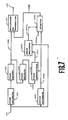
- Fig. 7 shows a block diagram of a moving image signal encoding apparatus in a fourth embodiment of the present invention.
- the numeral 101 is an input moving image signal
- 102 is a frame decimator
- 103 is a frame encoder
- 104 is a frame decoder
- 105 is a frame interpolator
- 107 is a transmitter and multiplexer
- 108 is an output signal of the moving image signal encoding apparatus
- 1091 is a motion estimator
- 1093 is an error evaluator
- 1094 is a selector.
- the frame decimator 102 decimates the frames of the input moving image signal 101 to one-half.
- the operation of the frame decimator 102 is the same as that of the first embodiment.
- the frame encoder 103 encodes the encoded frame to obtain the frame code 1038.
- the frame decoder 104 decodes the encoded frame to obtain the reproduced frame 1046.
- the frame interpolator 105 produces the interpolated frame 1051 from the motion vector 1092 and the reproduced frame 1046. The relationship between the reproduced frame and the interpolated frame is the same as that explained in the first embodiment.
- the error evaluator 1093 obtains the error of the interpolated frame 1051 and outputs a mode selection signal 10931.
- the mode selection signal becomes a code indicating a frame interpolation mode.
- the mode selection signal becomes a code indicating a previous value retaining mode.
- the selector 1094 outputs as its output 1096 the motion vector 1092 when the mode selection signal indicates the frame interpolation mode, and outputs a flag signal when the mode selection signal indicates the previous value retaining mode.
- the multiplexer and transmitter 107 multiplexes and outputs the frame code 1038 and the output 1096 of the selector 1094 as the output signal 108 of the moving image signal encoding apparatus:
- Fig. 8 shows a block diagram of the decoding apparatus in the fourth embodiment of the present invention.
- 201 is an input signal of the moving image signal decoding apparatus
- 202 is a receiver and demultiplexer
- 203 is a frame decoder
- 204 is a frame interpolator
- 206 is a selector
- 207 is an output signal of the moving image signal decoding apparatus.
- the moving image signal decoding apparatus 2 is to decode the inputted signal 201 and output the moving image signal 207.
- the inputted signal 201 is the output signal 108 of the moving image signal encoding apparatus of Fig. 6.
- the receiver and demultiplexer 202 extracts from the inputted signal 201 a frame code 2021 and a signal 2024 which is the motion vector or the flag signal.
- the operation sequence is as follows.
- the frame decoder 203 decodes the frame code 2021 to obtain the reproduced frame 2036.
- the frame interpolator 204 interpolates a frame between the reproduced frames.
- the selector 206 alternately selects the reproduced frames 2036 and the interpolated frames 2087 to obtain the output signal 207 of the moving image signal decoding apparatus.
- Fig. 9 (a) the output signal of the moving image signal decoding apparatus is shown, in which A′ and C′ are the reproduced frames, and Bi' and Di' are the interpolated frames.
- the operation sequence is as follows.
- the frame decoder 203 decodes the frame code 2021 to obtain the reproduced frame 2036.
- the frame interpolator 204 obtains the frame positioned between the reproduced frames by holding the preceding frame. The held previous reproduced frame is outputted as the output frame 2087. This operation is shown in Fig. 9 (b) .
- the frames A′ and C′ at the time t0 and t2 are the reproduced frames
- the frames A′ and C′ at the time t1 and t3 are those in which the frames A′ and C′ at the time t0 and t2 are respectively held for 1 frame period of time, i.e., the reproduced frames A′ and C′ are repeated.
- the selector 206 alternately selects the reproduced frames 2036 and the output frames 2087 of the frame interpolator 204 to obtain the output signal 207 of the moving image signal decoding apparatus.
- the output signal 207 is displayed as a reproduced image by the display apparatus 208.
Abstract
Description
- The present invention relates to a moving image signal encoding apparatus for performing compression encoding of a moving image signal for transmission of the moving image signal or recording of the same on a recording medium and a decoding apparatus for decoding the codes which have been transmitted or reproduced from a recording medium to obtain a reproduced image.
- Recently, in the moving image signal encoding apparatus and decoding apparatus, in consequence of the developments of television telephones and television conference systems, various compression encoding systems have been in practical use. As a procedure for curtailing the information amount to be used in these encoding systems there is a frame decimation. This is to curtail the information amount by decimating selected frames of the moving image signal in encoding. Since the movements of the reproduced images become unnatural by decimating the frames, frame interpolation is carried out in the decoding apparatus to obtain the reproduced images having smooth movements.
- As one of the precedents to carry out frame interpolation with a moving image signal decoding apparatus there is a construction shown in USP 4,727,422. Hereinafter, construction of the conventional moving image signal encoding apparatus and decoding apparatus is described.
- The input of the moving image signal encoding apparatus is a moving image signal of 30 frames/sec. The inputted moving image signal, after decimation of the number of frames to 1/2, becomes a moving image signal of 15 frames/sec. These remaining frames of the moving image signal will be encoded. In the description hereinafter, these frames are called "encoded frames". Inter-frame motion vectors are obtained from the encoded frames. The motion vectors are obtained on a block by block basis. The motion vectors are used for frame interpolation in the decoding apparatus. The encoded frames and the motion vectors are respectively encoded, after which additional information is incorporated to obtain an output signal of the moving image signal encoding apparatus. The output signal is sent out to a transmission channel or recorded on a recording medium.
- The moving image signal decoding apparatus is to decode the signal encoded by the moving image signal encoding apparatus and reproduce the moving image signal. By a signal receiving circuit, each code is received from the transmission channel or read out from the recording medium. The codes are decoded by respective decoding circuits to become the reproduced frames and the motion vectors. The frequency of the reproduced frames is 15 frames/sec. A frame interpolation circuit obtains interpolated frames each positioned between two reproduced frames. The frame interpolation is a motion compensating frame interpolation using a motion vector between the frames. By alternately outputting the interpolated frames and the reproduced frames, an output image signal of 30 frames/sec is obtained.
- Howevr, the above construction involves the problem to cause errors to the interpolated frames because there are no correct motion vectors in such cases that:
(1) there are objects which move in different directions from each other in a block; (2) the background appears from the shade of a moving object or the background is hidden by a moving object; (3) the moving object changes in shape; and (4) there is a movement accompanied with rotation. - An object of the present invention is to realize reduction in errors of interpolation of frames in a moving image signal encoding apparatus which decimates frames in encoding and a moving image signal decoding apparatus which interpolates frames in decoding.
- To achieve this object, a moving image signal encoding apparatus of the present invention comprises a frame decimator for extracting encoded frames from an input moving image signal at specified intervals, a frame encoder for encoding said encoded frames to obtain frame codes, a frame interpolator for producing interpolated frames positioned between said encoded frames from said frame codes, a motion estimator for evaluating errors of said interpolated frames, and a transmitter for transmitting said frame codes and output signals of said error evaluator as an output signal of the moving image signal encoding apparatus.
- A moving image signal decoding apparatus of the present invention is to decode the signals transmitted from the aforementioned moving image signal encoding apparatus, and comprises a receiver for extracting said frame codes and said error evaluator output signals from the input signal, a frame decoder for decoding said frame codes to obtainthe reproduced frames, and a frame interpolator for producing interpolated frames positioned between said reproduced frames.
- Preferably, said error evaluator includes means for encoding the errors of said interpolated frames to error codes, and said moving image signal decoding apparatus includes means for correcting the errors of said interpolated frames according to the error codes to obtain said reproduced frames and error-corrected interpolated frames in a specified sequence.
- Alternatively, said error evaluator includes means for obtaining the errors of said interpolated frames to obtain error codes and means for producing from the error codes a mode selection signal for changing over an operation mode of the frame interpolator of the moving image signal decoding apparatus, and, in the moving image signal decoding apparatus, the frame interpolator includes means for selecting whether to perform frame interpolation or to hold a preceding reproduced frame (to repeat the preceding reproduced frame) according to the mode selection signal, and outputs said reproduced frames and said interpolated frames in a specified sequence.
-
- Fig. 1 is a block diagram showing a moving image signal encoding apparatus and a moving image signal decoding apparatus in a first embodiment of the present invention;
- Fig. 2 is an illustrative view to explain a relation between frames;
- Fig. 3 is a block diagram of a moving image signal encoding apparatus in a second embodiment of the present invention;
- Fig. 4 is a block diagram of a moving image signal decoding apparatus in the second embodiment of the present invention;
- Fig. 5 is a block diagram of an error evaluator and coder of a moving image signal decoding apparatus in a third embodiment of the present invention;
- Fig. 6 is a view showing an interpolated frame divided into a plurality of blocks;
- Fig. 7 is a block diagram of a moving image signal encoding apparatus in a fourth embodiment of the present invention;
- Fig. 8 is a block diagram of a moving image signal decoding apparatus in the fourth embodiment of the present invention; and
- Fig. 9 is a view showing a relation between frames in the fourth embodiment of the present invention.
- Hereinafter, the moving image signal encoding apparatus and decoding apparatus according to the embodiments of the present invention are explained with referene to the drawings.
- Fig. 1 shows a block diagram of a moving image signal encoding apparatus and a decoding apparatus in a first embodiment of the present invention. In Fig. 1, the
numeral 1 denotes the moving image signal encoding apparatus for encoding and transmitting a moving image signal, in which 101 is an input moving image signal, 102 is a frame decimator, 103 is a frame encoder, 104 is a local frame decoder, 105 is a frame interpolator, 106 is an error calculator and coder, 107 is a multiplexer and transmitter, and 108 is an output signal of the moving image signal encoding apparatus. Thenumeral 2 denotes the moving image signal decoding apparatus for reproducing the moving image signal, in which 201 is an input signal of the moving image signal decoding apparatus, 202 is a receiver and demultiplexer, 203 is a frame decoder, 204 is a frame interpolator, 205 is an error corrector, 206 is a selector, and 207 is an output signal of the moving image signal decoding apparatus. - The operations of the moving image signal encoding apparatus and decoding apparatus constituted as above are explained by way of Fig. 1.
- To an input of the moving image signal encoding apparatus, a moving
image signal 101 to be encoded is inputted. Aframe decimator 102 decimates the frames of the input movingimage signal 101 to one-half. This operation is illustrated in Fig. 2 (a). A, B, C, D are the continued frames of the input moving image signal, of which B and D are the frames to be decimated by theframe decimator 102, and A and C are the frames to be inputted to theframe encoder 103. In the following explanation, frames A and C are called the "encoded frames". Theframe encoder 103 encodes each encoded frame to aframe code 1038. Theframe decoder 104 decodes the frame code to obtain a reproducedframe 1046. Theframe interpolator 105 synthesizes interpolatedframes 1051 each positioned between two reproduced frames. The relationship between the reproduced frames and the interpolated frames is explained in Fig. 2 (b) . A′ and C′ are the reproduced frames, and these correspond to the encoded frames A and C. The encoded frames A and C are encoded by theframe encoder 103 and then decoded by theframe decoder 104 to be the reproduced frames A′ and C′ . Bi and Di are the interpolated frames outputted by theframe interpolator 105. The error evaluator andcoder 106 encodes an error of each interpolated frame obtained as a difference between the interpolated frame and a corresponding frame of the input moving image signal, and outputs it as an interpolatedframe code 1066. The multiplexer andtransmitter 107 multiplexes the frame codes and the interpolated frame codes, and outputs the multiplexed result as anoutput signal 108 of the moving image signal encoding apparatus. - Next, the operations of the moving image
signal decoding apparatus 2 are explained. The moving imagesignal decoding apparatus 2 is to decode the inputtedsignal 201 and output a reproduced moving image signal. The inputtedsignal 201 is theoutput signal 108 of the moving imagesignal encoding apparatus 1. The receiver anddemultiplexer 202 extracts theframe codes 2021 and the interpolatedframe codes 2022 from the inputted signal. These codes are respectively equal to theframe codes 1038 and the interpolatedframe codes 1066 of the moving imagesignal encoding apparatus 1. Theframe decoder 203 decodes the frame codes and outputs reproduced frames 2036. Theframe interpolator 204 synthesizes interpolatedframes 2041 each positioned between two reproduced frames. The relationship between the reproduced frames and the interpolated frames is the same as in the case of the moving imagesignal encoding apparatus 1 as shown in Fig. 2 (b) . Theerror corrector 205 corrects the errors of the interpolated frames by using the interpolatedframe codes 2022. Theselector 206 alternately selects the reproducedframes 2036 and the error-correctedinterpolated frames 2037 to obtain theoutput signal 207 of the moving image signal encoding apparatus. Adisplay apparatus 208 displays the reproduced image based on theoutput signal 207 of the moving imagesignal encoding apparatus 2. - Fig. 3 shows a block diagram of a moving image signal encoding apparatus in a second embodiment of the present invention. In Fig. 3, the numeral 101 is an input moving image signal, 102 is a frame decimator, 103 is a frame encoder, 1033 is a subtraction circuit, 1035 is a DCT (discrete cosine transform) operation circuit, 1037 is a quantizer, 104 is a local frame decoder, 1041 is a dequantizer, 1043 is an inverse DCT (IDCT) operation circuit, 1045 is an addition circuit, 1047 is a frame memory, 1048 is a motion compensator, 105 is a frame interpolator, 106 is an error evaluator and coder, 1061 is a subtraction circuit, 1063 is a DCT operation circuit, 1065 is a quantizer, 107 is a multiplexer and transmitter, 108 is an output signal of the moving image signal encoding apparatus, and 1091 is a motion estimator.
- The operations of the moving image signal encoding apparatus constituted as above are explained by way of Fig. 3.
- The
motion estimator 1091 estimates the motion of the input movingimage signal 101 and outputs amotion vector 1092. - The
frame decimator 102 decimates the frames of the input moving image signal to one-half. The operation of theframe decimator 102 is the same as that of the first embodiment. - The
frame encoder 103 encodes the encodedframes 1031 to framecodes 1038. The encoding method is an interframe coding. Thesubtraction circuit 1033 obtains a predictederror signal 1034 which is a differential value between the encodedframe 1031 and a predictedframe 1032 formed by the later-describedlocal decoder 104. TheDCT operation circuit 1035 transforms the predictederror signal 1034 to aDCT coefficient 1036. Thequantizer 1037 quantizes theDCT coefficient 1036 to obtain theframe code 1038. - The
local decoder 104 decodes theframe code 1038 to obtain a reproducedframe 1046 and the predictedframe 1032. Thedequantizer 1041 dequantizes theframe code 1038 to obtain a reproducedDCT coefficient 1042. The inverseDCT operation circuit 1043 inverse discrete cosine transforms the reproducedDCT coefficient 1042 to obtain a reproduced predictederror signal 1044. Theaddition circuit 1045 adds the reproduced predictederror signal 1044 and the predictedframe 1032 to obtain the reproducedframe 1046. Theframe memory 1047 memorizes the reproducedframe 1046. Themotion compensator 1048 carries out a motion compensation of the reproduced frame read out from theframe memory 1047 according to themotion vector 1092 to obtain the predictedframe 1032. - The
frame interpolator 105 synthesizes an interpolatedframe 1051 from themotion vector 1092 and the reproducedframe 1046. The relationship between the reproduced frames and the interpolated frames is the same as that explained in the first embodiment. - The error evaluator and
coder 106 encodes the error of the interpolatedframe 1051 to obtain an interpolatedframe code 1066. Thesubtraction circuit 1061 calculates a differential value between the interpolatedframe 1051 and a corresponding frame of the input movingimage signal 101 to obtain an interpolatedframe error signal 1062. The DCT (Discrete Cosine Transform)operation circuit 1063 transforms the interpolatedframe error signal 1062 to aDCT coefficient 1064. Thequantizer 1065 quantizes theDCT coefficient 1064 to obtain the interpolatedframe code 1066. - The multiplexer and
transmitter 107 multiplexes and outputs theframe code 1038, themotion vector 1092, and the interpolatedframe code 1066 as theoutput signal 108 of the moving image signal encoding apparatus. - Fig. 4 shows a block diagram of a moving image signal decoding apparatus in the second embodiment of the present invention. In Fig. 4, the numeral 201 is an input signal of the moving image signal decoding apparatus, 202 is a receiver and multiplexer, 203 is a frame decoder, 2031 is a dequantizer, 2033 is an inverse DCT operation circuit, 2035 is an addition circuit, 2037 is a frame memory, 2038 is a motion compensator, 204 is a frame interpolator, 205 is an error corrector, 2051 is a dequantizer, 2053 is an inverse DCT operation circuit, 2055 is an addition circuit, 206 is a selector, and 207 is an output signal of the moving image signal decoding circuit.
- The operations of the moving image signal decoding apparatus constituted as above are explained by way of Fig. 4.
- The
input signal 201 is an output signal of the moving image signal encoding apparatus of Fig. 3. The receiver anddemultiplexer 202 extracts aframe code 2021, an interpolatedframe code 2022, and amotion vector 2023 from theinput signal 201. These codes are equal to theframe code 1038, the interpolatedframe code 1066, and themotion vector 1092, respectively, of the moving image signal encoding apparatus in Fig. 3. - The
frame decoder 203 decodes theframe code 2021 to obtain a reproducedframe 2036. Thedequantizer 2031 dequantizes theframe code 2031 to obtain a reproducedDCT coefficient 2032. The inverseDCT operation circuit 2035 inverse discrete cosine transforms the reproducedDCT coefficient 2032 to obtain a reproduced predictederror signal 2034. Theaddition circuit 2035 adds the reproduced predictederror signal 2034 and a predictedframe 2039 formed by the later-describedmotion compensator 2038 and to obtain the reproducedframe 2036. Theframe memory 2037 memorizes the reproducedframe 2036. Themotion compensator 2032 carries out a motion compensation of the reproduced frame read out from theframe memory 2037 according to themotion vector 2023 to obtain the predictedframe 2039. - The
frame interpolator 204 synthesizes an interpolatedframe 2041 from themotion vector 2023 and the reproducedframe 2036. The relationship between the reproduced frame and the interpolated frame is the same as explained in the first embodiment. - The
error corrector 205 corrects the error of the interpolatedframe 2041 by using the interpolatedframe code 2022. Thedequantizer 2051 dequantizes the interpolatedframe code 2022 to obtain a reproducedDCT coefficient 2052. The inverseDCT operation circuit 2053 inversely discrete cosine transforms the reproducedDCT coefficient 2052 to obtain an interpolated frame error signal 2054. Theaddition circuit 2055 adds the reproduced interpolated frame error signal 2054 and the interpolatedframe 2041 to obtain a reproduced interpolatedframe 2056. Theselector 206 alternately selects the reproducedframes 2036 and the reproduced interpolatedframes 2056 to obtain theoutput signal 207 of the moving image signal decoding apparatus and supplies theoutput signal 207 to thedisplay apparatus 208. - Fig. 5 shows a block diagram of an error evaluator and coder of a moving image signal encoding apparatus in a third embodiment of the present invention.
- The constructions of the other parts are the same as those in the second embodiment shown in Fig. 3. In Fig. 5, 1051 is an input interpolated frame, 101 is an input moving image signal of the moving image signal encoding apparatus, 1061 is a subtraction circuit, 1063 is a DCT operation circuit, 1065 is a quantizer, 1068 is an error calculator, 10611 is a comparator, 10610 is a reference level, 10613 is a switch, and 1066 is an interpolated frame code.
- The operations of the error evaluator and coder circuit constituted as above are explained by way of Fig. 5. The
subtraction circuit 1061 obtains an interpolatedframe error signal 1062 which is a differential value between the input interpolatedframe 1051 and the input movingimage signal 101. TheDCT operation circuit 1063 transforms the interpolatedframe error signal 1062 to aDCT coefficient 1064. Thequantizer 1065 quantizes theDCT coefficient 1064 to obtain acode 10614. Theerror calculator 1068 obtains the value of the interpolatedframe error signal 1062 on a block by block by block basis to obtain anerror value 1069. This block is explained with reference to Fig. 6. In Fig. 6, 3001 shows an interpolated frame, and 3002 is a block in this frame. The interpolated frame is divided at intervals of 8 image elements both vertically and horizontally to obtain each block. Thecomparator 1061 compares theerror value 1069 with a specifiedreference level 10610, and closes theswitch 1061 when theerror value 1069 exceeds thereference level 10610. When the switch is closed, theoutput code 10614 of thequantizer 1065 becomes the interpolatedframe code 1066 which is an output of the interpolated frame encoding circuit. - Fig. 7 shows a block diagram of a moving image signal encoding apparatus in a fourth embodiment of the present invention. In Fig. 7, the numeral 101 is an input moving image signal, 102 is a frame decimator, 103 is a frame encoder, 104 is a frame decoder, 105 is a frame interpolator, 107 is a transmitter and multiplexer, 108 is an output signal of the moving image signal encoding apparatus, 1091 is a motion estimator, 1093 is an error evaluator, and 1094 is a selector.
- The operations of the moving image signal encoding apparatus constituted as above are explained by way of Fig. 7.
- The
frame decimator 102 decimates the frames of the input movingimage signal 101 to one-half. The operation of theframe decimator 102 is the same as that of the first embodiment. - The
frame encoder 103 encodes the encoded frame to obtain theframe code 1038. Theframe decoder 104 decodes the encoded frame to obtain the reproducedframe 1046. Theframe interpolator 105 produces the interpolatedframe 1051 from themotion vector 1092 and the reproducedframe 1046. The relationship between the reproduced frame and the interpolated frame is the same as that explained in the first embodiment. - The
error evaluator 1093 obtains the error of the interpolatedframe 1051 and outputs amode selection signal 10931. When the error of the interpolated frame is smaller than a predetermined reference level, the mode selection signal becomes a code indicating a frame interpolation mode. When the error is larger than the reference level, the mode selection signal becomes a code indicating a previous value retaining mode. Theselector 1094 outputs as itsoutput 1096 themotion vector 1092 when the mode selection signal indicates the frame interpolation mode, and outputs a flag signal when the mode selection signal indicates the previous value retaining mode. - The multiplexer and
transmitter 107 multiplexes and outputs theframe code 1038 and theoutput 1096 of theselector 1094 as theoutput signal 108 of the moving image signal encoding apparatus: - Fig. 8 shows a block diagram of the decoding apparatus in the fourth embodiment of the present invention. In Fig. 8, 201 is an input signal of the moving image signal decoding apparatus, 202 is a receiver and demultiplexer, 203 is a frame decoder, 204 is a frame interpolator, 206 is a selector, and 207 is an output signal of the moving image signal decoding apparatus.
- The operations of the moving image signal decoding apparatus constituted as above are explained by way of Fig. 8.
- The moving image
signal decoding apparatus 2 is to decode the inputtedsignal 201 and output the movingimage signal 207. The inputtedsignal 201 is theoutput signal 108 of the moving image signal encoding apparatus of Fig. 6. The receiver anddemultiplexer 202 extracts from the inputted signal 201 aframe code 2021 and asignal 2024 which is the motion vector or the flag signal. - When the motion vector is extracted from the receiver and
demultiplexer 202, the operation sequence is as follows. Theframe decoder 203 decodes theframe code 2021 to obtain the reproducedframe 2036. Theframe interpolator 204 interpolates a frame between the reproduced frames. Theselector 206 alternately selects the reproducedframes 2036 and the interpolatedframes 2087 to obtain theoutput signal 207 of the moving image signal decoding apparatus. In Fig. 9 (a) the output signal of the moving image signal decoding apparatus is shown, in which A′ and C′ are the reproduced frames, and Bi' and Di' are the interpolated frames. - Further, when the flag signal is extracted as the
output 2024 of the receiver anddemultiplexer 202, the operation sequence is as follows. Theframe decoder 203 decodes theframe code 2021 to obtain the reproducedframe 2036. Theframe interpolator 204 obtains the frame positioned between the reproduced frames by holding the preceding frame. The held previous reproduced frame is outputted as theoutput frame 2087. This operation is shown in Fig. 9 (b) . The frames A′ and C′ at the time t0 and t2 are the reproduced frames, and the frames A′ and C′ at the time t1 and t3 are those in which the frames A′ and C′ at the time t0 and t2 are respectively held for 1 frame period of time, i.e., the reproduced frames A′ and C′ are repeated. Theselector 206 alternately selects the reproducedframes 2036 and the output frames 2087 of theframe interpolator 204 to obtain theoutput signal 207 of the moving image signal decoding apparatus. Theoutput signal 207 is displayed as a reproduced image by thedisplay apparatus 208.
Claims (9)
Applications Claiming Priority (6)
| Application Number | Priority Date | Filing Date | Title |
|---|---|---|---|
| JP1118004A JPH02296479A (en) | 1989-05-11 | 1989-05-11 | Transmitter for moving picture signal |
| JP118004/89 | 1989-05-11 | ||
| JP16305989A JPH0683441B2 (en) | 1989-06-26 | 1989-06-26 | Method and apparatus for inter-frame interpolation coding of image signal |
| JP163059/89 | 1989-06-26 | ||
| JP16932089A JP2695244B2 (en) | 1989-06-29 | 1989-06-29 | Image signal coding apparatus, image signal decoding apparatus, image signal coding method, and image signal decoding method |
| JP169320/89 | 1989-06-29 |
Publications (3)
| Publication Number | Publication Date |
|---|---|
| EP0397402A2 true EP0397402A2 (en) | 1990-11-14 |
| EP0397402A3 EP0397402A3 (en) | 1992-04-29 |
| EP0397402B1 EP0397402B1 (en) | 1996-07-10 |
Family
ID=27313485
Family Applications (1)
| Application Number | Title | Priority Date | Filing Date |
|---|---|---|---|
| EP90304841A Expired - Lifetime EP0397402B1 (en) | 1989-05-11 | 1990-05-03 | Moving image signal encoding- and decoding apparatus |
Country Status (7)
| Country | Link |
|---|---|
| US (1) | US5113255A (en) |
| EP (1) | EP0397402B1 (en) |
| KR (1) | KR930002119B1 (en) |
| AU (1) | AU612543B2 (en) |
| CA (1) | CA2016523C (en) |
| DE (1) | DE69027710T2 (en) |
| ES (1) | ES2091790T3 (en) |
Cited By (19)
| Publication number | Priority date | Publication date | Assignee | Title |
|---|---|---|---|---|
| WO1992014339A1 (en) * | 1991-02-01 | 1992-08-20 | British Telecommunications Public Limited Company | Method and apparatus for decoding video signals |
| EP0556507A1 (en) * | 1991-10-22 | 1993-08-25 | Sony Corporation | Image signal coding and decoding apparatus |
| EP0631444A1 (en) * | 1992-03-03 | 1994-12-28 | Kabushiki Kaisha Toshiba | Time-varying image encoder |
| WO1995002303A1 (en) * | 1993-07-07 | 1995-01-19 | Rca Thomson Licensing Corporation | Method and apparatus for providing scaleable compressed video signal |
| US5436665A (en) * | 1992-03-03 | 1995-07-25 | Kabushiki Kaisha Toshiba | Motion picture coding apparatus |
| EP0720383A1 (en) * | 1994-12-30 | 1996-07-03 | Daewoo Electronics Co., Ltd | Method and apparatus for detecting motion vectors in a frame decimating video encoder |
| EP0721284A1 (en) * | 1995-01-09 | 1996-07-10 | Daewoo Electronics Co., Ltd | An image processing system using pixel-by-pixel motion estimation and frame decimation |
| FR2729266A1 (en) * | 1995-01-10 | 1996-07-12 | France Telecom | METHOD FOR INTERPOLATING IMAGES |
| EP0734165A3 (en) * | 1995-03-20 | 1998-03-11 | Daewoo Electronics Co., Ltd | Image processing system using pixel-by-pixel motion estimation and frame decimation |
| US5973739A (en) * | 1992-03-27 | 1999-10-26 | British Telecommunications Public Limited Company | Layered video coder |
| CN1075320C (en) * | 1993-04-13 | 2001-11-21 | 三星电子株式会社 | Method of and apparatus for coding in which quantizing degree can be changed according to character of energy of frequency zone |
| CN1112045C (en) * | 1993-09-14 | 2003-06-18 | 恩威特奇公司 | Carry out video compression with error information coding method repeatedly |
| WO2003055226A1 (en) * | 2001-12-21 | 2003-07-03 | Koninklijke Philips Electronics N.V. | Method and apparatus for motion compensated temporal interpolation of video sequences |
| GB2401502A (en) * | 2003-05-07 | 2004-11-10 | British Broadcasting Corp | Image data encoding and transmission |
| CN106492460A (en) * | 2016-12-08 | 2017-03-15 | 搜游网络科技(北京)有限公司 | A kind of compression method of data and equipment |
| US9888237B2 (en) | 2002-01-25 | 2018-02-06 | Microsoft Technology Licensing, Llc | Video coding |
| US10063863B2 (en) | 2003-07-18 | 2018-08-28 | Microsoft Technology Licensing, Llc | DC coefficient signaling at small quantization step sizes |
| US10116959B2 (en) | 2002-06-03 | 2018-10-30 | Microsoft Technology Licesning, LLC | Spatiotemporal prediction for bidirectionally predictive (B) pictures and motion vector prediction for multi-picture reference motion compensation |
| US10554985B2 (en) | 2003-07-18 | 2020-02-04 | Microsoft Technology Licensing, Llc | DC coefficient signaling at small quantization step sizes |
Families Citing this family (79)
| Publication number | Priority date | Publication date | Assignee | Title |
|---|---|---|---|---|
| GB9405914D0 (en) * | 1994-03-24 | 1994-05-11 | Discovision Ass | Video decompression |
| EP0576749B1 (en) * | 1992-06-30 | 1999-06-02 | Discovision Associates | Data pipeline system |
| US5341318A (en) * | 1990-03-14 | 1994-08-23 | C-Cube Microsystems, Inc. | System for compression and decompression of video data using discrete cosine transform and coding techniques |
| JPH0556275A (en) * | 1990-08-30 | 1993-03-05 | Sharp Corp | Image coder and image decoder |
| JPH04207788A (en) * | 1990-11-30 | 1992-07-29 | Sony Corp | Band compression device |
| US5253275A (en) * | 1991-01-07 | 1993-10-12 | H. Lee Browne | Audio and video transmission and receiving system |
| JPH04246992A (en) * | 1991-01-31 | 1992-09-02 | Sony Corp | Image conversion device |
| JP2581341B2 (en) * | 1991-04-26 | 1997-02-12 | 日本ビクター株式会社 | High efficiency encoding device and decoding device |
| EP0533195A2 (en) * | 1991-09-20 | 1993-03-24 | Sony Corporation | Picture signal encoding and/or decoding apparatus |
| JP2962012B2 (en) * | 1991-11-08 | 1999-10-12 | 日本ビクター株式会社 | Video encoding device and decoding device therefor |
| US5351086A (en) * | 1991-12-31 | 1994-09-27 | Daewoo Electronics Co., Ltd. | Low-bit rate interframe video encoder with adaptive transformation block selection |
| JP3230263B2 (en) * | 1992-01-31 | 2001-11-19 | ソニー株式会社 | Motion vector detection circuit |
| JP3042142B2 (en) * | 1992-02-28 | 2000-05-15 | 日本電気株式会社 | Semiconductor integrated circuit |
| JPH05268594A (en) * | 1992-03-18 | 1993-10-15 | Sony Corp | Motion detector for moving picture |
| US5367385A (en) * | 1992-05-07 | 1994-11-22 | Picturetel Corporation | Method and apparatus for processing block coded image data to reduce boundary artifacts between adjacent image blocks |
| KR0121162B1 (en) * | 1992-05-20 | 1997-11-18 | 구자홍 | Compensating device of image moving in digital tv |
| JPH05344493A (en) * | 1992-06-10 | 1993-12-24 | Victor Co Of Japan Ltd | Dynamic image coder |
| US5473441A (en) * | 1992-06-12 | 1995-12-05 | Fuji Photo Film Co., Ltd. | Video signal reproduction processing method and apparatus for reproduction of a recorded video signal as either a sharp still image or a clear moving image |
| EP0577310B1 (en) * | 1992-06-29 | 2001-11-21 | Canon Kabushiki Kaisha | Image processing device |
| US6435737B1 (en) * | 1992-06-30 | 2002-08-20 | Discovision Associates | Data pipeline system and data encoding method |
| US7095783B1 (en) | 1992-06-30 | 2006-08-22 | Discovision Associates | Multistandard video decoder and decompression system for processing encoded bit streams including start codes and methods relating thereto |
| US6079009A (en) * | 1992-06-30 | 2000-06-20 | Discovision Associates | Coding standard token in a system compromising a plurality of pipeline stages |
| US5768561A (en) * | 1992-06-30 | 1998-06-16 | Discovision Associates | Tokens-based adaptive video processing arrangement |
| US6047112A (en) * | 1992-06-30 | 2000-04-04 | Discovision Associates | Technique for initiating processing of a data stream of encoded video information |
| US5809270A (en) * | 1992-06-30 | 1998-09-15 | Discovision Associates | Inverse quantizer |
| US5603012A (en) * | 1992-06-30 | 1997-02-11 | Discovision Associates | Start code detector |
| US6067417A (en) * | 1992-06-30 | 2000-05-23 | Discovision Associates | Picture start token |
| US6112017A (en) * | 1992-06-30 | 2000-08-29 | Discovision Associates | Pipeline processing machine having a plurality of reconfigurable processing stages interconnected by a two-wire interface bus |
| US6330665B1 (en) | 1992-06-30 | 2001-12-11 | Discovision Associates | Video parser |
| JPH0620050A (en) * | 1992-07-03 | 1994-01-28 | Matsushita Electric Ind Co Ltd | Dynamic image signal decoding device and estimated motion vector calculation method |
| KR970000761B1 (en) * | 1992-10-07 | 1997-01-18 | 대우전자 주식회사 | Mini high-definition television |
| US5426462A (en) * | 1993-05-13 | 1995-06-20 | Intel Corporation | Apparatus for encoding signals using a configurable transform circuit |
| EP0625853B1 (en) * | 1993-05-21 | 1999-03-03 | Nippon Telegraph And Telephone Corporation | Moving image encoder and decoder |
| US5684534A (en) * | 1993-05-26 | 1997-11-04 | Intel Corporation | Task-splitting dual-processor system for motion estimation processing |
| KR970000683B1 (en) * | 1993-05-31 | 1997-01-16 | 삼성전자 주식회사 | Resolution adaptive video compression/decompression method and apparatus |
| US5805914A (en) * | 1993-06-24 | 1998-09-08 | Discovision Associates | Data pipeline system and data encoding method |
| US5699544A (en) * | 1993-06-24 | 1997-12-16 | Discovision Associates | Method and apparatus for using a fixed width word for addressing variable width data |
| US5861894A (en) * | 1993-06-24 | 1999-01-19 | Discovision Associates | Buffer manager |
| JP2776212B2 (en) * | 1993-08-04 | 1998-07-16 | 日本ビクター株式会社 | Code recording device |
| CA2145365C (en) * | 1994-03-24 | 1999-04-27 | Anthony M. Jones | Method for accessing banks of dram |
| CA2145361C (en) * | 1994-03-24 | 1999-09-07 | Martin William Sotheran | Buffer manager |
| CA2145379C (en) * | 1994-03-24 | 1999-06-08 | William P. Robbins | Method and apparatus for addressing memory |
| US5852669A (en) * | 1994-04-06 | 1998-12-22 | Lucent Technologies Inc. | Automatic face and facial feature location detection for low bit rate model-assisted H.261 compatible coding of video |
| US5534925A (en) * | 1994-05-02 | 1996-07-09 | Cognitech Inc. | Image compression by optimal reconstruction |
| JP3604732B2 (en) * | 1994-07-01 | 2004-12-22 | キヤノン株式会社 | Video system |
| US6217234B1 (en) * | 1994-07-29 | 2001-04-17 | Discovision Associates | Apparatus and method for processing data with an arithmetic unit |
| GB9417138D0 (en) | 1994-08-23 | 1994-10-12 | Discovision Ass | Data rate conversion |
| US5943096A (en) | 1995-03-24 | 1999-08-24 | National Semiconductor Corporation | Motion vector based frame insertion process for increasing the frame rate of moving images |
| GB2301970B (en) * | 1995-06-06 | 2000-03-01 | Sony Uk Ltd | Motion compensated video processing |
| US5598777A (en) | 1995-10-02 | 1997-02-04 | Howard W. DeMoore | Retractable printing/coating unit operable on the plate and blanket cylinders |
| US5651316A (en) | 1995-10-02 | 1997-07-29 | Howard W. DeMoore | Retractable printing/coating unit operable on the plate and blanket cylinders simultaneously from the dampener side of the first printing unit or any consecutive printing unit of any rotary offset printing press |
| EP0767058A3 (en) | 1995-10-02 | 1998-06-10 | DeMoore, Howard W. | Printing press |
| US6031575A (en) * | 1996-03-22 | 2000-02-29 | Sony Corporation | Method and apparatus for encoding an image signal, method and apparatus for decoding an image signal, and recording medium |
| JP3844844B2 (en) * | 1997-06-06 | 2006-11-15 | 富士通株式会社 | Moving picture coding apparatus and moving picture coding method |
| US7263127B1 (en) | 1998-04-02 | 2007-08-28 | Intel Corporation | Method and apparatus for simplifying frame-based motion estimation |
| US6904174B1 (en) | 1998-12-11 | 2005-06-07 | Intel Corporation | Simplified predictive video encoder |
| US7046734B2 (en) * | 1998-04-02 | 2006-05-16 | Intel Corporation | Method and apparatus for performing real-time data encoding |
| US6584154B1 (en) * | 1998-11-26 | 2003-06-24 | Oki Electric Industry Co., Ltd. | Moving-picture coding and decoding method and apparatus with reduced computational cost |
| US20020135695A1 (en) * | 2001-03-26 | 2002-09-26 | Edelson Steven D. | Video data reduction by selected frame elimination |
| US7154952B2 (en) | 2002-07-19 | 2006-12-26 | Microsoft Corporation | Timestamp-independent motion vector prediction for predictive (P) and bidirectionally predictive (B) pictures |
| US7813429B2 (en) * | 2002-08-13 | 2010-10-12 | Lsi Corporation | System and method for segmentation of macroblocks |
| US7020200B2 (en) * | 2002-08-13 | 2006-03-28 | Lsi Logic Corporation | System and method for direct motion vector prediction in bi-predictive video frames and fields |
| US20050013498A1 (en) | 2003-07-18 | 2005-01-20 | Microsoft Corporation | Coding of motion vector information |
| US7724827B2 (en) | 2003-09-07 | 2010-05-25 | Microsoft Corporation | Multi-layer run level encoding and decoding |
| US7567617B2 (en) | 2003-09-07 | 2009-07-28 | Microsoft Corporation | Predicting motion vectors for fields of forward-predicted interlaced video frames |
| US8064520B2 (en) | 2003-09-07 | 2011-11-22 | Microsoft Corporation | Advanced bi-directional predictive coding of interlaced video |
| US8861601B2 (en) * | 2004-08-18 | 2014-10-14 | Qualcomm Incorporated | Encoder-assisted adaptive video frame interpolation |
| WO2007003340A2 (en) * | 2005-07-01 | 2007-01-11 | Nero Ag | Video encoder and video decoder |
| US9077960B2 (en) | 2005-08-12 | 2015-07-07 | Microsoft Corporation | Non-zero coefficient block pattern coding |
| US8233535B2 (en) | 2005-11-18 | 2012-07-31 | Apple Inc. | Region-based processing of predicted pixels |
| US20070116117A1 (en) * | 2005-11-18 | 2007-05-24 | Apple Computer, Inc. | Controlling buffer states in video compression coding to enable editing and distributed encoding |
| US8780997B2 (en) | 2005-11-18 | 2014-07-15 | Apple Inc. | Regulation of decode-side processing based on perceptual masking |
| US8295343B2 (en) * | 2005-11-18 | 2012-10-23 | Apple Inc. | Video bit rate control method |
| US8031777B2 (en) | 2005-11-18 | 2011-10-04 | Apple Inc. | Multipass video encoding and rate control using subsampling of frames |
| US8437397B2 (en) * | 2007-01-04 | 2013-05-07 | Qualcomm Incorporated | Block information adjustment techniques to reduce artifacts in interpolated video frames |
| US8254455B2 (en) | 2007-06-30 | 2012-08-28 | Microsoft Corporation | Computing collocated macroblock information for direct mode macroblocks |
| US7860996B2 (en) | 2008-05-30 | 2010-12-28 | Microsoft Corporation | Media streaming with seamless ad insertion |
| JP2010004142A (en) * | 2008-06-18 | 2010-01-07 | Hitachi Kokusai Electric Inc | Moving picture encoder, decoder, encoding method, and decoding method |
| US8189666B2 (en) | 2009-02-02 | 2012-05-29 | Microsoft Corporation | Local picture identifier and computation of co-located information |
Citations (1)
| Publication number | Priority date | Publication date | Assignee | Title |
|---|---|---|---|---|
| US4727422A (en) * | 1985-06-03 | 1988-02-23 | Picturetel Corporation | Method and apparatus for efficiently communicating image sequence having improved motion compensation |
Family Cites Families (5)
| Publication number | Priority date | Publication date | Assignee | Title |
|---|---|---|---|---|
| US4383272A (en) * | 1981-04-13 | 1983-05-10 | Bell Telephone Laboratories, Incorporated | Video signal interpolation using motion estimation |
| JP2670259B2 (en) * | 1985-11-29 | 1997-10-29 | ソニー株式会社 | High efficiency coding device |
| US4700232A (en) * | 1986-10-24 | 1987-10-13 | Grass Valley Group, Inc. | Interpolator for television special effects system |
| JP2508439B2 (en) * | 1987-05-29 | 1996-06-19 | ソニー株式会社 | High efficiency encoder |
| US4958226A (en) * | 1989-09-27 | 1990-09-18 | At&T Bell Laboratories | Conditional motion compensated interpolation of digital motion video |
-
1990
- 1990-04-30 AU AU54516/90A patent/AU612543B2/en not_active Expired
- 1990-05-03 ES ES90304841T patent/ES2091790T3/en not_active Expired - Lifetime
- 1990-05-03 DE DE69027710T patent/DE69027710T2/en not_active Expired - Lifetime
- 1990-05-03 EP EP90304841A patent/EP0397402B1/en not_active Expired - Lifetime
- 1990-05-10 CA CA002016523A patent/CA2016523C/en not_active Expired - Lifetime
- 1990-05-11 US US07/522,121 patent/US5113255A/en not_active Ceased
- 1990-05-11 KR KR1019900006697A patent/KR930002119B1/en not_active IP Right Cessation
Patent Citations (1)
| Publication number | Priority date | Publication date | Assignee | Title |
|---|---|---|---|---|
| US4727422A (en) * | 1985-06-03 | 1988-02-23 | Picturetel Corporation | Method and apparatus for efficiently communicating image sequence having improved motion compensation |
Non-Patent Citations (7)
| Title |
|---|
| * page 611, column 1, line 33 - page 612, column1, line 18; figure 1 * * |
| SMPTE JOURNAL. vol. 98, no. 7, July 1989, WHITE PLAINS pages 504 - 511; SABRI ET AL.: 'A MODULAR DIGITAL VIDEO CODING ARCHITECTURE FOR PRESENT AND ADVANCED TV SYSTEMS' * |
| SMPTE JOURNAL. vol. 98, no. 7, July 1989, WHITE PLAINS pages 504 - 511; SABRI ET AL.: 'A MODULAR DIGITAL VIDEO CODING ARCHITECTURE FOR PRESENT AND ADVANCED TV SYSTEMS', * page 508, column 1, line 13 - page 511, column 2, line 2; figures 11,12,16* * |
| SYMPOSIUM RECORD BROADCAST SESSIONS, 16TH INTERNATIONAL TV SYMPOSIUM 17 June 1989, MONTREUX pages 387 - 409; GROTZ ET AL.: 'IMAGE CODING TECHNIQUES FOR 64 KBIT/S CHANNELS' * |
| SYMPOSIUM RECORD BROADCAST SESSIONS, 16TH INTERNATIONAL TV SYMPOSIUM 17 June 1989, Montreux, pages 387-409; Grotz et al.: "IMAGE CODING TECHNIQUES FOR 64 KBIT/S CHANNELS" * page 389, line 1 - line 16; figure 2*, * page 390, line 1 - line 31; figure 6* * |
| THE TRANSACTIONS OF THE I.E.C.E. OF JAPAN vol. 70, no. 7, July 1987, TOKYO JP pages 611 - 613; TANIMOTO ET AL.: 'A HYBRID SCHEME OF SUBSAMPLED DPCM AND INTERPOLATIVE DPCM FOR THE HDTV CODING' * |
| THE TRANSACTIONS OF THE I.E.C.E. OF JAPAN vol. 70, no. 7, July 1987, TOKYO JP pages 611 - 613; TANIMOTO ET AL.: 'A HYBRID SCHEME OF SUBSAMPLED DPCM AND INTERPOLATIVE DPCM FOR THE HDTV CODING',page 611, column 1, line 33 - page 612, column 1, line 18; figure 1 * |
Cited By (32)
| Publication number | Priority date | Publication date | Assignee | Title |
|---|---|---|---|---|
| US5418571A (en) * | 1991-02-01 | 1995-05-23 | British Telecommunicatons Public Limited Company | Decoding of double layer video signals with interpolation replacement on missing data from enhancement layer |
| WO1992014339A1 (en) * | 1991-02-01 | 1992-08-20 | British Telecommunications Public Limited Company | Method and apparatus for decoding video signals |
| EP0556507A1 (en) * | 1991-10-22 | 1993-08-25 | Sony Corporation | Image signal coding and decoding apparatus |
| US5337086A (en) * | 1991-10-22 | 1994-08-09 | Sony Corporation | Image signal coding and decoding apparatus with multiple-process motion compensation |
| EP0631444A1 (en) * | 1992-03-03 | 1994-12-28 | Kabushiki Kaisha Toshiba | Time-varying image encoder |
| EP0631444A4 (en) * | 1992-03-03 | 1995-01-11 | ||
| US5436665A (en) * | 1992-03-03 | 1995-07-25 | Kabushiki Kaisha Toshiba | Motion picture coding apparatus |
| US5973739A (en) * | 1992-03-27 | 1999-10-26 | British Telecommunications Public Limited Company | Layered video coder |
| CN1075320C (en) * | 1993-04-13 | 2001-11-21 | 三星电子株式会社 | Method of and apparatus for coding in which quantizing degree can be changed according to character of energy of frequency zone |
| WO1995002303A1 (en) * | 1993-07-07 | 1995-01-19 | Rca Thomson Licensing Corporation | Method and apparatus for providing scaleable compressed video signal |
| CN1112045C (en) * | 1993-09-14 | 2003-06-18 | 恩威特奇公司 | Carry out video compression with error information coding method repeatedly |
| EP0720383A1 (en) * | 1994-12-30 | 1996-07-03 | Daewoo Electronics Co., Ltd | Method and apparatus for detecting motion vectors in a frame decimating video encoder |
| US5619281A (en) * | 1994-12-30 | 1997-04-08 | Daewoo Electronics Co., Ltd | Method and apparatus for detecting motion vectors in a frame decimating video encoder |
| CN1103164C (en) * | 1995-01-09 | 2003-03-12 | 大宇电子株式会社 | An image processing system using pixel-by-pixel motion estimation and frame decimation |
| EP0721284A1 (en) * | 1995-01-09 | 1996-07-10 | Daewoo Electronics Co., Ltd | An image processing system using pixel-by-pixel motion estimation and frame decimation |
| US5933547A (en) * | 1995-01-10 | 1999-08-03 | France Telecom | Method for interpolating images |
| EP0722251A1 (en) * | 1995-01-10 | 1996-07-17 | France Telecom | Method for interpolating images |
| FR2729266A1 (en) * | 1995-01-10 | 1996-07-12 | France Telecom | METHOD FOR INTERPOLATING IMAGES |
| EP0734165A3 (en) * | 1995-03-20 | 1998-03-11 | Daewoo Electronics Co., Ltd | Image processing system using pixel-by-pixel motion estimation and frame decimation |
| CN1115879C (en) * | 1995-03-20 | 2003-07-23 | 大宇电子株式会社 | Image processing system using pixel-by-pixel motion estimation and frame decimation |
| WO2003055226A1 (en) * | 2001-12-21 | 2003-07-03 | Koninklijke Philips Electronics N.V. | Method and apparatus for motion compensated temporal interpolation of video sequences |
| US9888237B2 (en) | 2002-01-25 | 2018-02-06 | Microsoft Technology Licensing, Llc | Video coding |
| US10284843B2 (en) | 2002-01-25 | 2019-05-07 | Microsoft Technology Licensing, Llc | Video coding |
| US10116959B2 (en) | 2002-06-03 | 2018-10-30 | Microsoft Technology Licesning, LLC | Spatiotemporal prediction for bidirectionally predictive (B) pictures and motion vector prediction for multi-picture reference motion compensation |
| GB2401502B (en) * | 2003-05-07 | 2007-02-14 | British Broadcasting Corp | Data processing |
| GB2401502A8 (en) * | 2003-05-07 | 2005-04-14 | British Broadcasting Corp | Image date encoding and transmission |
| GB2401502A (en) * | 2003-05-07 | 2004-11-10 | British Broadcasting Corp | Image data encoding and transmission |
| US10063863B2 (en) | 2003-07-18 | 2018-08-28 | Microsoft Technology Licensing, Llc | DC coefficient signaling at small quantization step sizes |
| US10554985B2 (en) | 2003-07-18 | 2020-02-04 | Microsoft Technology Licensing, Llc | DC coefficient signaling at small quantization step sizes |
| US10659793B2 (en) | 2003-07-18 | 2020-05-19 | Microsoft Technology Licensing, Llc | DC coefficient signaling at small quantization step sizes |
| CN106492460A (en) * | 2016-12-08 | 2017-03-15 | 搜游网络科技(北京)有限公司 | A kind of compression method of data and equipment |
| CN106492460B (en) * | 2016-12-08 | 2019-12-24 | 搜游网络科技(北京)有限公司 | Data compression method and equipment |
Also Published As
| Publication number | Publication date |
|---|---|
| DE69027710D1 (en) | 1996-08-14 |
| AU5451690A (en) | 1990-11-15 |
| EP0397402B1 (en) | 1996-07-10 |
| DE69027710T2 (en) | 1997-02-06 |
| CA2016523C (en) | 1994-02-15 |
| KR930002119B1 (en) | 1993-03-26 |
| AU612543B2 (en) | 1991-07-11 |
| KR900019506A (en) | 1990-12-24 |
| US5113255A (en) | 1992-05-12 |
| EP0397402A3 (en) | 1992-04-29 |
| CA2016523A1 (en) | 1990-11-11 |
| ES2091790T3 (en) | 1996-11-16 |
Similar Documents
| Publication | Publication Date | Title |
|---|---|---|
| US5113255A (en) | Moving image signal encoding apparatus and decoding apparatus | |
| USRE35910E (en) | Moving image signal encoding apparatus and decoding apparatus | |
| EP0526163B1 (en) | Image coding method and image coding apparatus | |
| JP3314929B2 (en) | Video signal encoding circuit | |
| US6631214B1 (en) | Image coder and image coding method | |
| US7486734B2 (en) | Decoding and coding method of moving image signal, and decoding and coding apparatus of moving image signal using the same | |
| US6795498B1 (en) | Decoding apparatus, decoding method, encoding apparatus, encoding method, image processing system, and image processing method | |
| US20010050957A1 (en) | Image decoding method | |
| JP2695244B2 (en) | Image signal coding apparatus, image signal decoding apparatus, image signal coding method, and image signal decoding method | |
| JP2010087754A (en) | Image quality evaluation device | |
| JPH012486A (en) | High efficiency code decoding device |
Legal Events
| Date | Code | Title | Description |
|---|---|---|---|
| PUAI | Public reference made under article 153(3) epc to a published international application that has entered the european phase |
Free format text: ORIGINAL CODE: 0009012 |
|
| AK | Designated contracting states |
Kind code of ref document: A2 Designated state(s): CH DE ES FR GB IT LI NL SE |
|
| PUAL | Search report despatched |
Free format text: ORIGINAL CODE: 0009013 |
|
| AK | Designated contracting states |
Kind code of ref document: A3 Designated state(s): CH DE ES FR GB IT LI NL SE |
|
| 17P | Request for examination filed |
Effective date: 19920929 |
|
| 17Q | First examination report despatched |
Effective date: 19940913 |
|
| GRAH | Despatch of communication of intention to grant a patent |
Free format text: ORIGINAL CODE: EPIDOS IGRA |
|
| GRAH | Despatch of communication of intention to grant a patent |
Free format text: ORIGINAL CODE: EPIDOS IGRA |
|
| GRAH | Despatch of communication of intention to grant a patent |
Free format text: ORIGINAL CODE: EPIDOS IGRA |
|
| GRAH | Despatch of communication of intention to grant a patent |
Free format text: ORIGINAL CODE: EPIDOS IGRA |
|
| GRAA | (expected) grant |
Free format text: ORIGINAL CODE: 0009210 |
|
| AK | Designated contracting states |
Kind code of ref document: B1 Designated state(s): CH DE ES FR GB IT LI NL SE |
|
| REG | Reference to a national code |
Ref country code: CH Ref legal event code: NV Representative=s name: KIRKER & CIE SA |
|
| ITF | It: translation for a ep patent filed |
Owner name: JACOBACCI & PERANI S.P.A. |
|
| REF | Corresponds to: |
Ref document number: 69027710 Country of ref document: DE Date of ref document: 19960814 |
|
| ET | Fr: translation filed | ||
| REG | Reference to a national code |
Ref country code: ES Ref legal event code: FG2A Ref document number: 2091790 Country of ref document: ES Kind code of ref document: T3 |
|
| PLBE | No opposition filed within time limit |
Free format text: ORIGINAL CODE: 0009261 |
|
| STAA | Information on the status of an ep patent application or granted ep patent |
Free format text: STATUS: NO OPPOSITION FILED WITHIN TIME LIMIT |
|
| 26N | No opposition filed | ||
| REG | Reference to a national code |
Ref country code: GB Ref legal event code: IF02 |
|
| REG | Reference to a national code |
Ref country code: CH Ref legal event code: PFA Owner name: PANASONIC CORPORATION Free format text: MATSUSHITA ELECTRIC INDUSTRIAL CO., LTD.#1006, KADOMA#KADOMA-SHI, OSAKA-FU 571 (JP) -TRANSFER TO- PANASONIC CORPORATION#1006, OAZA KADOMA, KADOMA-SHI#OSAKA 571-8501 (JP) |
|
| NLT1 | Nl: modifications of names registered in virtue of documents presented to the patent office pursuant to art. 16 a, paragraph 1 |
Owner name: PANASONIC CORPORATION |
|
| REG | Reference to a national code |
Ref country code: ES Ref legal event code: PC2A |
|
| PGFP | Annual fee paid to national office [announced via postgrant information from national office to epo] |
Ref country code: NL Payment date: 20090517 Year of fee payment: 20 Ref country code: ES Payment date: 20090609 Year of fee payment: 20 |
|
| REG | Reference to a national code |
Ref country code: FR Ref legal event code: CD |
|
| PGFP | Annual fee paid to national office [announced via postgrant information from national office to epo] |
Ref country code: DE Payment date: 20090429 Year of fee payment: 20 Ref country code: IT Payment date: 20090516 Year of fee payment: 20 Ref country code: FR Payment date: 20090515 Year of fee payment: 20 Ref country code: SE Payment date: 20090512 Year of fee payment: 20 |
|
| PGFP | Annual fee paid to national office [announced via postgrant information from national office to epo] |
Ref country code: CH Payment date: 20090513 Year of fee payment: 20 |
|
| PGFP | Annual fee paid to national office [announced via postgrant information from national office to epo] |
Ref country code: GB Payment date: 20090429 Year of fee payment: 20 |
|
| REG | Reference to a national code |
Ref country code: NL Ref legal event code: V4 Effective date: 20100503 |
|
| REG | Reference to a national code |
Ref country code: CH Ref legal event code: PL |
|
| REG | Reference to a national code |
Ref country code: GB Ref legal event code: PE20 Expiry date: 20100502 |
|
| EUG | Se: european patent has lapsed | ||
| REG | Reference to a national code |
Ref country code: ES Ref legal event code: FD2A Effective date: 20100504 |
|
| PG25 | Lapsed in a contracting state [announced via postgrant information from national office to epo] |
Ref country code: NL Free format text: LAPSE BECAUSE OF EXPIRATION OF PROTECTION Effective date: 20100503 |
|
| PG25 | Lapsed in a contracting state [announced via postgrant information from national office to epo] |
Ref country code: ES Free format text: LAPSE BECAUSE OF EXPIRATION OF PROTECTION Effective date: 20100504 |
|
| PG25 | Lapsed in a contracting state [announced via postgrant information from national office to epo] |
Ref country code: GB Free format text: LAPSE BECAUSE OF EXPIRATION OF PROTECTION Effective date: 20100502 |
|
| PG25 | Lapsed in a contracting state [announced via postgrant information from national office to epo] |
Ref country code: DE Free format text: LAPSE BECAUSE OF EXPIRATION OF PROTECTION Effective date: 20100503 |