EP0397397B1 - Automatic heating apparatus - Google Patents
Automatic heating apparatus Download PDFInfo
- Publication number
- EP0397397B1 EP0397397B1 EP90304824A EP90304824A EP0397397B1 EP 0397397 B1 EP0397397 B1 EP 0397397B1 EP 90304824 A EP90304824 A EP 90304824A EP 90304824 A EP90304824 A EP 90304824A EP 0397397 B1 EP0397397 B1 EP 0397397B1
- Authority
- EP
- European Patent Office
- Prior art keywords
- air
- heating
- sensor means
- passage
- steam gas
- Prior art date
- Legal status (The legal status is an assumption and is not a legal conclusion. Google has not performed a legal analysis and makes no representation as to the accuracy of the status listed.)
- Expired - Lifetime
Links
Images


Classifications
-
- F—MECHANICAL ENGINEERING; LIGHTING; HEATING; WEAPONS; BLASTING
- F24—HEATING; RANGES; VENTILATING
- F24C—DOMESTIC STOVES OR RANGES ; DETAILS OF DOMESTIC STOVES OR RANGES, OF GENERAL APPLICATION
- F24C7/00—Stoves or ranges heated by electric energy
- F24C7/08—Arrangement or mounting of control or safety devices
-
- H—ELECTRICITY
- H05—ELECTRIC TECHNIQUES NOT OTHERWISE PROVIDED FOR
- H05B—ELECTRIC HEATING; ELECTRIC LIGHT SOURCES NOT OTHERWISE PROVIDED FOR; CIRCUIT ARRANGEMENTS FOR ELECTRIC LIGHT SOURCES, IN GENERAL
- H05B6/00—Heating by electric, magnetic or electromagnetic fields
- H05B6/64—Heating using microwaves
- H05B6/642—Cooling of the microwave components and related air circulation systems
-
- H—ELECTRICITY
- H05—ELECTRIC TECHNIQUES NOT OTHERWISE PROVIDED FOR
- H05B—ELECTRIC HEATING; ELECTRIC LIGHT SOURCES NOT OTHERWISE PROVIDED FOR; CIRCUIT ARRANGEMENTS FOR ELECTRIC LIGHT SOURCES, IN GENERAL
- H05B6/00—Heating by electric, magnetic or electromagnetic fields
- H05B6/64—Heating using microwaves
- H05B6/6408—Supports or covers specially adapted for use in microwave heating apparatus
- H05B6/6411—Supports or covers specially adapted for use in microwave heating apparatus the supports being rotated
-
- H—ELECTRICITY
- H05—ELECTRIC TECHNIQUES NOT OTHERWISE PROVIDED FOR
- H05B—ELECTRIC HEATING; ELECTRIC LIGHT SOURCES NOT OTHERWISE PROVIDED FOR; CIRCUIT ARRANGEMENTS FOR ELECTRIC LIGHT SOURCES, IN GENERAL
- H05B6/00—Heating by electric, magnetic or electromagnetic fields
- H05B6/64—Heating using microwaves
- H05B6/6447—Method of operation or details of the microwave heating apparatus related to the use of detectors or sensors
- H05B6/645—Method of operation or details of the microwave heating apparatus related to the use of detectors or sensors using temperature sensors
-
- H—ELECTRICITY
- H05—ELECTRIC TECHNIQUES NOT OTHERWISE PROVIDED FOR
- H05B—ELECTRIC HEATING; ELECTRIC LIGHT SOURCES NOT OTHERWISE PROVIDED FOR; CIRCUIT ARRANGEMENTS FOR ELECTRIC LIGHT SOURCES, IN GENERAL
- H05B6/00—Heating by electric, magnetic or electromagnetic fields
- H05B6/64—Heating using microwaves
- H05B6/6447—Method of operation or details of the microwave heating apparatus related to the use of detectors or sensors
- H05B6/6458—Method of operation or details of the microwave heating apparatus related to the use of detectors or sensors using humidity or vapor sensors
Definitions
- the present invention relates to an automatic heating apparatus having a sensing system which senses steam of elevated temperature generated from a heated material in accordance with the state of heating and controls a heating source in response to a detection signal delivered from the sensing system.
- the sensing system of such conventional automatic heating apparatus uses most generally, as a sensing element, a humidity sensor which senses a change in the humidity.
- a humidity sensor serves to sense a change in the electric resistance of the sensor caused by molecules of water adsorbed to the surface of the sensor such complicated structure and operation have been required that the contamination on the surface of the element must be burnt away periodically with use of a heater in order to maintain a stable performance over a long time while avoiding any deterioration in the sensitivity or the like attributable to contamination of the surface of the sensor.
- the present invention aims at eliminating the above-described problems of the prior art and is constructed such that steam gas generated from a heated material in a heating chamber is stably and quickly drawn out from a heating chamber and, after making contact with a sensor means, is discharged to the outside of an apparatus. It is therefore an object of the present invention to provide an automatic heating apparatus which can quickly sense, by means of a sensor means, any increase or decrease in the amount of steam gas caused by a change in the state of a heated material, thus realizing good finish of the heated material.
- an automatic heating apparatus comprising; a heating chamber for storing therein material to be heated; heating means for heating the material in said heating chamber; sensor means for detecting a heated condition of said material; a guide passage for guiding air to said sensor means from said heating chamber; control means for controlling said heating means in accordance with a signal from said sensor means; and suction means for introducing said air to said sensor means from said heating chamber through said guide passage, said suction means including a blower means having a suction side and a blowing side, characterised in that said suction means includes an intake portion for receiving air from said blower means and an air flow path for air passing into said intake which path provides a negative pressure region the arrangement being such that air driven out and pressurised by said blower means is led into negative pressure region through said intake portion, and then flows into an exhaust passage which communicates with the exterior of the apparatus through an outlet, and air from said heating chamber is sucked through said guide passage into the exhaust passage, and wherein said sensor means is composed of a sensing member having
- the suction means act to draw out the steam gas from the heating chamber quickly and stably.
- the suction utilises the fact that the pressure of air is increased when a flow of air induced by a blower means including propeller blades is restricted by a heating means such as a magnetron. Provision of an air passage which runs from a region where the pressure is thus increased to the outside of the apparatus where the pressure is relatively low and which provides a small resistance, causes the air of an increased pressure to rush through the air passage of the small air resistance. This rush of air serves to create in the air passage a region where the pressure is lower than that in the heating chamber, as stated in Bernoulli theorem. The lower pressure region causes steam gas to be drawn out from the heating chamber.
- a guide passage is therefore connected to the suction means for guiding steam gas from the heating chamber.
- An exhaust passage which provides a small exhaust resistance is connected to the suction means for discharging the steam gas guided thereto through the guide passage.
- a sensor means for sensing the state of temperature of the steam gas is exposed to any of the guide passage, exhaust passage and the air passage of the suction means while serving as a part of the wall of the passage.
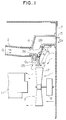
- a guide passage 2 which is connected to a heating chamber 1 and through which steam gas generated from a heated material is guided is connected to a suction means 5.
- the suction means 5 serves to produce a pressure lower than that in the heating chamber 1 so as to cause the steam gas in the heating chamber 1 to be drawn out.
- the suction means 5 is also connected to an exhaust passage 4 through which the steam gas drawn out from the heating chamber 1 is discharged.
- An outlet 15 of an air passage of the suction means 5, through which the exhaust air such as the steam gas flows out, is formed in a shell 7 of the apparatus.
- a sensor means 3 for sensing the state of heating of the heated material is arranged, which also serves as a part of the wall of the air passage of the suction means 5.
- the suction means 5 makes use of a fact that the pressure of air is increased when a flow of air induced by a blower means including propeller blades 17 is restricted by a heating means such as a magnetron 11.
- An air passage which gives a small air resistance is provided so as to run from an intake portion 25 of the suction means 5 located in a region where the pressure is thus increased to the outside of the apparatus where the pressure is relatively low, so that the air of the increased pressure rushes through the air passage of the small air resistance, and then is discharged through the outlet 15 of the suction means 5.
- This rush of air serves to create in the air passage a negative pressure region 6 where the pressure is lower than that in the heating chamber 1, as explained by the Bernoulli theorem.
- the negative pressure region 6 causes the steam gas to be drawn out from the heating chamber 1.
- the guide passage 2 is connected to the suction means 5 for guiding the steam gas from the heating chamber 1.
- the exhaust passage 4 which gives a small exhaust resistance is connected to the suction means 5 for discharging the steam gas guided thereto through the guide passage 2.
- the sensor means 3 for sensing the state of temperature of the steam gas is disposed being exposed to the exhaust passage 4 or the air passage of the suction means 5 while serving as a part of the wall of the passage.
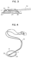
- the sensor means 3 will be described with reference to Figures 3 and 4.
- the sensor means 3 has the pyroelectricity with which the sensor means 3 produces a signal voltage in response to an instantaneous change in the temperature.
- the pyroelectricity can be given by charges which are distributed on the surface of a dielectric member due to internal polarization of the latter. Namely, when a dielectric member which has been subjected to internal polarization experiences an abrupt change of temperature by being irradiated with a heat carried by light, infrared radiation, steam gas of boiling water or the like or exposed to cold air to be cooled, the internal polarization of the dielectric member is extinguished so that the charges remain only on the surface of the dielectric member. This condition gives the pyroelectricity. It is possible to utilize the charges remaining on the surface by connecting this dielectric member to an electrical circuit. This element is generally referred to as "pyroelectric element”.
- a certain type of pyroelectric elements also has piezoelectric properties, and includes a piezoelectric ceramic used for a piezoelectric buzzer or a supersonic vibrator, a filmy polyvinylidene fluoride or the like.
- the amount of charges of the pyroelectric element is proportional to the surface area thereof, the larger the surface area, the higher the ability to sense a change in temperature becomes.
- the pyroelectric element can sense the signals effectively when it is formed in such a shape that is capable of collecting the maximum amount of charges, that is, in the shape of a plate which can ensure a large area by being provided thereon with parallel opposed electrodes.
- An electrode 31 is arranged covering the opposite sides of a plate pyroelectric element 29 such as a piezoelectric ceramic.
- a lead wire 32 is connected to the electrode 31 by soldering at a point 33.
- the pyroelectric element 29 is stuck to a metallic plate 28 by an adhesive 34.
- the pyroelectric element 29, the electrode 31 and the like are coated with a resin film 30 in order to avoid exposing them to the atmosphere.
- the pyroelectric element 29 and the metallic plate 28 are formed in a shape similar to a circle in order to minimize affection by difference in the heat transfer coefficient and the thermal expansion coefficient.
- the metallic plate 28 of the sensor means 3 is not disposed horizontally but inclinedly, so that the steam gas is made to flow down in the form of water droplets even if condensed into dew drops. Such construction enables the stream of the steam gas to flow without any hindrance.
- This air passage has a smaller ventilating cross-sectional area at the intake portion 25 than at the vent hole in the shell which serves as the outlet 15. This air passage therefore gives a small air resistance.
- a blower means for supplying a cooling air to the magnetron 11 as the heating means is arranged between vent holes 35 through which air is sucked from the outside of the apparatus by means of a motor 8 provided with the propeller blades 17 and a heating section including the magnetron 11 as the heating means, a high-voltage transformer 9 and the like, so as to supply cold air to the heating section.
- An orifice 18 is provided in the vicinity of the propeller blades 17 for setting the direction of air flow, so that the region of blown air is separated from the region of the sucked air.
- the air passage of the suction means 5 is designed to have a greater ventilating cross-sectional area in the region close to the outlet 15 than in the region close to the intake portion 25, resulting in that the air passage provides a larger air resistance in the region in the vicinity of the outlet 15 than in the region in the vicinity of the intake portion 25.
- the guide passage 2 through which the steam gas generated from the heated material 13 in the heating chamber 1 is guided is connected to the air passage of the suction means 5 at a position in the vicinity of the intake portion 25 where the ventilating cross-sectional area is small. Therefore, the guide passage 2 is connected to the air passage at a position where the air flows at a high velocity. A region where the air flows at the high velocity becomes the negative pressure region 6 so as to allow the steam gas to be draw out from the guide passage 2.
- the steam gas drawn out from the heating chamber 1 and the high velocity air which creates a negative pressure in the suction means 5 are mixed together and the thus mixed gas is discharged to the outside of the apparatus.
- the exhaust passage through which the thus-mixed gas flows has a ventilating cross-sectional area which is greater than a total cross-sectional area which is the sum of the ventilating cross-sectional area of the air passage of the suction means 5 at the intake portion 25 and the ventilating cross-sectional area of a vent hole at the juncture between the guide passage 2 led from the heating chamber 1 and the air passage, serving as the suction means 5, thereby preventing the resistance to the air flow from increasing in the exhaust passage.
- a surface of the metallic plate 28 of the sensor means 3 exposed to the guide passage 2 or the exhaust passage 4 constitutes a part of the wall thereof. Therefore, since the steam gas does not come in direct contact with the pyroelectric element 29, it is possible to prevent the sensor means 3 from being erroneously operated caused by deterioration of insulation. Further, since the steam gas comes in contact with the metallic plate 28, any change in the heat of the steam gas can be transmitted to the entire surface of the pyroelectric element 29.
- the portion with which the sensor means 3 comes in contact has to be an electric insulator.
- This portion also serves as a heat insulator. It is therefore possible to prevent leakage of the charges on the sensor means 3 and to sense the state of heating of the heated material 13 accurately. Since the sensor means 3 is enclosed by the heat insulator, only the heat of the steam gas in the air is transferred to the sensor means 3, with the result that the change of state can be sensed accurately and suitably in accordance with the state of heating of the heated material 13.
- the suction means 5 is provided with a projection 36 or an air passage wall member so that the ventilating cross-sectional area of the air passage in the region in the vicinity of the intake portion 25 of the air passage is made smaller than that of a vent hole at the juncture between the guide passage 2 led from the heating chamber 1 and the air passage of the suction means 5, giving rise to a vortex flow in the negative pressure region 6 which is created when the high velocity air supplied through the intake portion 25 passes through the air passage. Due to this vortex flow, the steam gas from the heating chamber 1 and the high velocity air are mixed together, that is the steam gas is diffused in the air passage of the suction means 5. The steam gas thus diffused is made to come in contact with the metallic plate 28 of the sensor means 3. Since the steam gas is made to come in contact with the metallic plate 28 in this way, the sensor means 3 can sense the change of state in accordance with the change in the state of heating of the heated material 13.
- the metallic plate 28 as a heat receiving surface of the sensor means 3 is arranged in the wall of the air passage at a position which is opposed to the vent hole at the juncture between the guide passage 2 led from the heating chamber 1 and the air passage and which is located on the outlet 15 side. Therefore, the steam gas from the heating chamber 1, which is mixed with the high velocity air is driven away by the high velocity air while making contact with the metallic plate 28, whereby dew drops stuck to the metallic plate 28 are blown away or dried. Accordingly, the metallic plate 28 can be maintained in the state where a change in the heat of the steam gas is easily transferred thereto.
- the sensor means 3 is arranged to serve as a part of the wall of the air passage of the suction means 5 and a part of the wall of the guide passage 2 led from the heating chamber 1. Since the sensor means 3 is planar, one of the surfaces of the sensor means 3 serves as the wall of the air passage of the suction means 5 and the other surface thereof serves as the wall of the guide passage 2, resulting in that one of the surfaces of the sensor means 3 is continuously exposed to the high velocity air and the other to the steam gas induced from the heating chamber 1.
- the heat of elevated temperature steam gas is transmitted to the cold pyroelectric element 29 of the sensor means 3.
- the steam gas reaches the sensor means 3 before it is mixed with the high velocity air so as to lower its temperature. It is therefore possible to realize the signal detection with high sensitivity in accordance with a change in the state of the steam gas.
- the surface of the metallic plate 28 of the sensor means 3 is arranged to serve as the wall surface of the guide passage 2 through which the steam gas induced from the heating chamber 1 is guided, and the pyroelectric element 29 of the sensor means 3 is arranged to serve as the wall surface of the air passage of the suction means 5. Therefore, the steam gas comes in contact with the surface of the metallic plate 28 so that the change in the temperature of the steam gas can be easily transmitted to the entire pyroelectric element 29. Further, since the steam gas does not reach the pyroelectric element 29, the electrical insulation can be maintained, and since the pyroelectric element 29 is in contact with the high velocity air at all times, the pyroelectric element 29 can be cooled quickly even if the heat of the steam gas is transmitted thereto.
- a door 26 is attached to the heating chamber 1 of the automatic heating apparatus.
- a control panel 21 is disposed by the side of the door 26, to which control commands for controlling the operation of the automatic heating apparatus are inputted.
- a turntable on which a material 13 to be heated is adapted to be placed is provided in the heating chamber 1.
- the turntable is rotated by a turntable motor 12.
- the material 13 is heated with an electromagnetic wave supplied from the magnetron 11 as the heating means.
- a lamp 10 emits light onto the heated material 3 through an opening formed in the wall of the heating chamber 1.
- the magnetron 11 is supplied with an electric power by a high-voltage generating means such as the high-voltage transformer 9.
- a blower means which produces streams of cooling air for cooling the high-voltage transformer 9, the turntable motor 12, the magnetron 11 as the heating means and the like, comprises the propeller blades 17 and the motor 18.
- a heating process is commenced by setting the heated material 13 in the heating chamber 1 and depressing a heating start instruction key after selection of a desired automatic heating function on the menu listed on the control panel 21.
- the commencement of the heating process means that a control unit starts a predetermined operation in accordance with the inputted data delivered from the control panel 21. More specifically, a control signal is sent from the control unit 22 to a driving means 23 so that the turntable motor 12, the high-voltage transformer 9, the magnetron 11, the lamp 10 and the motor 8 as the blower means are activated. Simultaneously with the start of heating, the air used for cooling the magnetron 11 and the lamp 10 is compelled to enter the heating chamber 1 due to the pressure of air driven out by the propeller blades 17.
- the air entered into the heating chamber 1 is allowed to flow out from exhaust openings formed in the wall of the heating chamber 1.
- the air is allowed to flow out of the heating chamber 1 from two exhaust openings, that is, an exhaust opening 19 having a sufficiently large ventilating cross-sectional area and another exhaust opening 14 having a smaller ventilating cross-sectional area.
- an exhaust opening 19 having a sufficiently large ventilating cross-sectional area and another exhaust opening 14 having a smaller ventilating cross-sectional area the most of the exhaust air is discharged to the outside of the apparatus via the exhaust opening 19 having a greater ventilating cross-sectional area and a discharge port 20.
- the remaining small part of the exhaust air containing the steam gas is drawn out through the exhaust opening 14 of the smaller ventilating cross-sectional area by means of the suction means 5.
- the steam gas drawn out through the exhaust opening 14 is caused to pass through an exhaust guide 16 and the guide passage 2 and reach the negative pressure region 6 in the air passage of the suction means 5. Then a change in the temperature of the steam gas responding to the state of heating of the heated material 13 is transmitted to the sensor means 3 provided on the wall along which the steam gas flows.
- the flow of air driven out by the propeller blades 17 is restricted by the magnetron 11 as the heating means, so that the pressure of air in a region between the magnetron 11 and the propeller blades 17 is increased.
- the air passage of the suction means 5 is provided such that the intake portion 25 is located in this increased pressure region and the outlet 15 is located in a region where the pressure is equal to the pressure of the air outside the apparatus.
- the exhaust passage 4 includes the outlet 15 of the air passage of the suction means 5.
- This signal processing means includes a low-pass filter circuit, a high-pass filter circuit, an amplifier circuit, a wave detector circuit and the like, which serves to amplify a pulse signal attributable to the fluctuation of the temperature change of the steam gas while maintaining the low frequency.
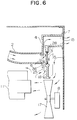
- Figure 6 shows another embodiment of the present invention.
- the air passage of the suction means 5 is made narrow so that a vortex flow of air produced by a projection 36 provided in the vicinity of the intake portion 25 is allowed to easily reach the metallic plate 28 of the sensor means 3.
- This vortex flow of air creates the negative pressure region 6, causing the steam gas to be drawn out from the heating chamber 1 and, at the same time, mixes the steam gas and the cold air flowing at a high velocity together.
- FIG. 7 shows still another embodiment of the present invention.
- steam gas drawn out by virtue of the negative pressure region 6 which is produced by the air flowing at a high velocity through the air passage of the suction means 5, and the high velocity air are made to flow in parallel with each other so that a layer of steam gas is allowed to flow along side of the metallic plate 28 of the sensor means 3.
- only a part of the steam gas layer which is not mixed with the high velocity air is made to come in contact with the metallic plate 28 of the sensor means 3, thus ensuring transmission of a signal indicative of a heat possessed by the steam gas without causing any drop in the temperature. Accordingly, a change in the temperature of the heated material 13 in the heating chamber 1 can be sensed with a high sensitivity.
- Figure 8 shows a further embodiment of the present invention.
- a planar surface of the pyroelectric element 29 of the sensor means 3 is arranged in the air passage of the suction means 5 to serve as a part of the wall of the air passage for air flowing at a high velocity
- a planar surface of the metallic plate 28 opposite to the pyroelectric element 29 is arranged to serve as a part of the wall along which the steam gas from the guide passage 2 flows.
- the sensor means 3 is provided as a boundary wall between the air passage for the high velocity air and the guide passage 2 which are adjacent to each other.
- the pyroelectric element 29 is constantly exposed to the cold air flowing at the high velocity, and therefore, even if heat caused by a change in the temperature of the steam gas is transmitted to the pyroelectric element 29, it is removed at once without being stored. Since heat is not accumulated in the pyroelectric element 29, the temperature of the pyroelectric element 29 can be kept at a lower level although the heating apparatus is repeatedly used. Since the temperature of the pyroelectric element 29 can be kept at the lower level, a change in the state of heating of the heated material 13 can be sensed accurately by the sensor means 3 in stable manner.
- the sensor means is provided to serve as a part of the wall of the air passage of the suction means, the exhaust passage or the guide passage it is possible to prevent the sensor means from giving a resistance to air flow in each passage. Thus, a negative pressure can be produced stably so as to cause the steam gas to be drawn out quickly.
- the sensor means employs the pyroelectric element of the planar shape which can provide a planar surface having a large area to which heat possessed by the steam gas is transmitted.
- the large heat receiving area contributes to the improvement in the sensitivity with which a change in the heat of the steam gas is sensed.
- the pyroelectric element of the sensor means is bonded to the metallic plate, a change in the heat of the steam gas can be transmitted to the entire pyroelectric element in a moment. This contributes to quick sensing of a change in the temperature of the steam gas. Further, the pyroelectric element is reinforced by the strength possessed by the metallic plate so as to have a high deformation resistance.
- the heating means is disposed at a position where the flow of air for cooling the heating means is restricted, the air flow resistance is increased and air is compressed by the blower means, resulting in an increased pressure.
- the air passage has a larger ventilating cross-sectional area at the outlet than at the inlet, the exhaust resistance is made smaller in this air passage.
- the blower means includes the propeller blades 17, the region of blown air and the region of drawn air are partitioned apart by the propeller blades 17, thus assuring the increase of the pressure of the blown air.
- the air passage Since the air passage has a greater ventilating cross-sectional area in the region around the outlet than in the region around the inlet, the air passage gives a smaller exhaust resistance in the vicinity of the outlet than in the vicinity of the inlet.
- Air having an increased pressure flows vigorously into the air passage through the small and narrow inlet and, then, flows toward the exhaust passage in which the pressure is lower than that in the region in the vicinity of the inlet.
- air flows at a high velocity in the region of the air passage in the vicinity of the inlet where the pressure is lower than that in the heating chamber.
- the guide passage is connected to the air passage at a position located in the vicinity of the inlet where the pressure is reduced.
- the ventilating cross-sectional area of the exhaust passage is greater than the sum of the two cross-sectional areas, that is, the ventilating cross-sectional area of the air passage at the inlet and the cross-sectional area of the vent hole at the juncture between the guide passage and the air passage, the air passage gives a smaller exhaust resistance in the vicinity of the outlet than in the vicinity of the inlet.
- the metallic plane of the sensor means is exposed to the guide passage or the exhaust passage, a change in the temperature of the steam gas can be quickly propagated over the entire pyroelectric element and sensed in stable manner. Further, the pyroelectric element is prevented from coming in direct contact with the steam gas, thus preventing any deterioration of insulation attributable to sticking of water droplets.
- the guide passage, the exhaust passage and the air passage, to any of which the sensor means can be fixed, are formed by the electric insulators. This contributes to the prevention of the leakage of current from the electric signals produced by the sensor means even if the sensor element is fixed to any passage. Further, since the electric insulator also serves as the heat insulator, the heat transmitted from the steam gas to the passages is prevented from being transmitted to the sensor means. Accordingly, the signal indicative of the steam gas sensed by the sensor means corresponds only to a change in the temperature sensed by the sensor means.
- the metallic plate of the sensor means is not horizontal but inclined, dew drops formed by condensation of the steam gas on the metallic plate are caused to flow down. Further, since the dew drops on the metallic plate do not cover the entire surface of the metallic plate, the steam gas is allowed to come in contact with the exposed metallic plate at all times.
- the projection or the air passage wall member is provided in such a manner that the cross-sectional area of the air passage in the vicinity of the inlet is made smaller than that of the vent hole at the juncture between the guide passage and the air passage, the steam gas induced from the guide passage is caused to flow into the air passage along the projection. Thus, the steam gas is diffused into the air passage.
- the heat receiving surface of the sensor means is arranged in the wall of the air passage at a position which is opposed to the vent hole at the juncture between the guide passage and the air passage, a mixture of the steam gas induced from the guide passage and the cold air flowing at the high velocity is brought into contact with the heat receiving surface of the sensor means.
- a single sensor means is arranged to serve as both part of the wall of the guide passage and as part of the wall of the air passage, that is, the planar surface of the metallic plate of the sensor means is exposed to the guide passage and the planar surface of the pyroelectric element of the sensor means is exposed to the air passage.
- the pyroelectric element is cooled by the air flowing at the high velocity and heat possessed by the steam gas maintained at elevated temperature can be transmitted through the metallic plate to the pyroelectric element.
Landscapes
- Physics & Mathematics (AREA)
- Electromagnetism (AREA)
- Engineering & Computer Science (AREA)
- Chemical & Material Sciences (AREA)
- Combustion & Propulsion (AREA)
- Mechanical Engineering (AREA)
- General Engineering & Computer Science (AREA)
- Electric Ovens (AREA)
- Control Of High-Frequency Heating Circuits (AREA)
Description
- The present invention relates to an automatic heating apparatus having a sensing system which senses steam of elevated temperature generated from a heated material in accordance with the state of heating and controls a heating source in response to a detection signal delivered from the sensing system.
- Various types of heating apparatus incorporating a system for automatically sensing the finish of heating of a heated material have hitherto been put into practice. The sensing system of such conventional automatic heating apparatus uses most generally, as a sensing element, a humidity sensor which senses a change in the humidity. However, since the humidity sensor serves to sense a change in the electric resistance of the sensor caused by molecules of water adsorbed to the surface of the sensor such complicated structure and operation have been required that the contamination on the surface of the element must be burnt away periodically with use of a heater in order to maintain a stable performance over a long time while avoiding any deterioration in the sensitivity or the like attributable to contamination of the surface of the sensor.
- On the other hand, we have proposed in foreign applications with the right of priority claiming based on Japanese Laid Open No. 2-44124 a sensing system in which a high temperature gas or vapor such as steam gas generated from a heated material with the progress of heating is drawn out through a vent hole formed in the wall of a heating chamber and brought into contact with a pyroelectric element provided outside of the heating chamber so as to sense the finish of the heating in accordance with a voltage produced by the pyroelectric element. In this type of sensing system, the sensing mechanism is based on a physical phenomenon of heat transfer from steam to the pyroelectric element. Thus, the sensitivity is not changed greatly due to the contamination of the surface of the element unlike the conventional humidity sensors, resulting in an advantage that is theoretically possible to provide a very simple sensing system. Another prior art arrangement which uses a sensing system is described in EP-A-0289000.
- These systems, however, have an inherent defect as well such that a long-time cooking causes the temperature of the pyroelectric element itself to rise and, as a result, a difference in the temperature between the pyroelectric element and the steam generated from the food becomes small, resulting in a lowering of sensitivity. To cope with this, it is required to use the pyroelectric element while cooling it as suggested in the above-mentioned foreign applications, and, in addition, it is required to develop an efficient sensing system at low cost which is commertially available.
- The present invention aims at eliminating the above-described problems of the prior art and is constructed such that steam gas generated from a heated material in a heating chamber is stably and quickly drawn out from a heating chamber and, after making contact with a sensor means, is discharged to the outside of an apparatus. It is therefore an object of the present invention to provide an automatic heating apparatus which can quickly sense, by means of a sensor means, any increase or decrease in the amount of steam gas caused by a change in the state of a heated material, thus realizing good finish of the heated material.
- According to the present invention there is provided an automatic heating apparatus comprising; a heating chamber for storing therein material to be heated; heating means for heating the material in said heating chamber; sensor means for detecting a heated condition of said material; a guide passage for guiding air to said sensor means from said heating chamber; control means for controlling said heating means in accordance with a signal from said sensor means; and suction means for introducing said air to said sensor means from said heating chamber through said guide passage, said suction means including a blower means having a suction side and a blowing side, characterised in that said suction means includes an intake portion for receiving air from said blower means and an air flow path for air passing into said intake which path provides a negative pressure region the arrangement being such that air driven out and pressurised by said blower means is led into negative pressure region through said intake portion, and then flows into an exhaust passage which communicates with the exterior of the apparatus through an outlet, and air from said heating chamber is sucked through said guide passage into the exhaust passage, and wherein said sensor means is composed of a sensing member having a sensitive surface which is arranged in the vicinity of said negative pressure region.
- In embodiments in accordance with the invention the suction means act to draw out the steam gas from the heating chamber quickly and stably. The suction utilises the fact that the pressure of air is increased when a flow of air induced by a blower means including propeller blades is restricted by a heating means such as a magnetron. Provision of an air passage which runs from a region where the pressure is thus increased to the outside of the apparatus where the pressure is relatively low and which provides a small resistance, causes the air of an increased pressure to rush through the air passage of the small air resistance. This rush of air serves to create in the air passage a region where the pressure is lower than that in the heating chamber, as stated in Bernoulli theorem. The lower pressure region causes steam gas to be drawn out from the heating chamber. A guide passage is therefore connected to the suction means for guiding steam gas from the heating chamber. An exhaust passage which provides a small exhaust resistance is connected to the suction means for discharging the steam gas guided thereto through the guide passage. A sensor means for sensing the state of temperature of the steam gas is exposed to any of the guide passage, exhaust passage and the air passage of the suction means while serving as a part of the wall of the passage.
- The present invention will be described now by way of example only, with particular reference to the accompanying drawings. In the drawings:
- Figure 1 is an enlarged sectional view of an embodiment of the present invention, showing essential portions thereof;
- Figure 2 is a block diagram showing functional components of the same embodiment;
- Figure 3 is a sectional view of a sensor means according to the present invention;
- Figure 4 is a perspective view of the same sensor means;
- Figure 5 is a perspective view of an automatic heating apparatus according to the present invention; and
- Figures 6 to 8 are enlarged sectional views of other embodiments of the present invention, showing essential portions thereof.
- A first embodiment of the present invention- will be described in detail with reference to Figures 1 and 2.
- As shown in Figures 1 and 2, a
guide passage 2 which is connected to a heating chamber 1 and through which steam gas generated from a heated material is guided is connected to a suction means 5. The suction means 5 serves to produce a pressure lower than that in the heating chamber 1 so as to cause the steam gas in the heating chamber 1 to be drawn out. The suction means 5 is also connected to anexhaust passage 4 through which the steam gas drawn out from the heating chamber 1 is discharged. Anoutlet 15 of an air passage of the suction means 5, through which the exhaust air such as the steam gas flows out, is formed in ashell 7 of the apparatus. A sensor means 3 for sensing the state of heating of the heated material is arranged, which also serves as a part of the wall of the air passage of the suction means 5. - The suction means 5 makes use of a fact that the pressure of air is increased when a flow of air induced by a blower means including
propeller blades 17 is restricted by a heating means such as a magnetron 11. An air passage which gives a small air resistance is provided so as to run from anintake portion 25 of the suction means 5 located in a region where the pressure is thus increased to the outside of the apparatus where the pressure is relatively low, so that the air of the increased pressure rushes through the air passage of the small air resistance, and then is discharged through theoutlet 15 of the suction means 5. This rush of air serves to create in the air passage a negative pressure region 6 where the pressure is lower than that in the heating chamber 1, as explained by the Bernoulli theorem. The negative pressure region 6 causes the steam gas to be drawn out from the heating chamber 1. For this reason, theguide passage 2 is connected to the suction means 5 for guiding the steam gas from the heating chamber 1. Theexhaust passage 4 which gives a small exhaust resistance is connected to the suction means 5 for discharging the steam gas guided thereto through theguide passage 2. The sensor means 3 for sensing the state of temperature of the steam gas is disposed being exposed to theexhaust passage 4 or the air passage of the suction means 5 while serving as a part of the wall of the passage. - The sensor means 3 will be described with reference to Figures 3 and 4. The sensor means 3 has the pyroelectricity with which the sensor means 3 produces a signal voltage in response to an instantaneous change in the temperature. The pyroelectricity can be given by charges which are distributed on the surface of a dielectric member due to internal polarization of the latter. Namely, when a dielectric member which has been subjected to internal polarization experiences an abrupt change of temperature by being irradiated with a heat carried by light, infrared radiation, steam gas of boiling water or the like or exposed to cold air to be cooled, the internal polarization of the dielectric member is extinguished so that the charges remain only on the surface of the dielectric member. This condition gives the pyroelectricity. It is possible to utilize the charges remaining on the surface by connecting this dielectric member to an electrical circuit. This element is generally referred to as "pyroelectric element".
- A certain type of pyroelectric elements also has piezoelectric properties, and includes a piezoelectric ceramic used for a piezoelectric buzzer or a supersonic vibrator, a filmy polyvinylidene fluoride or the like.
- Since the amount of charges of the pyroelectric element is proportional to the surface area thereof, the larger the surface area, the higher the ability to sense a change in temperature becomes.
- The pyroelectric element can sense the signals effectively when it is formed in such a shape that is capable of collecting the maximum amount of charges, that is, in the shape of a plate which can ensure a large area by being provided thereon with parallel opposed electrodes.
- In order to transmit the value of the charges on these surfaces to an electrical circuit, it is necessary to arrange an electrode in the direction corresponding to the direction of polarization. An
electrode 31 is arranged covering the opposite sides of a platepyroelectric element 29 such as a piezoelectric ceramic. Alead wire 32 is connected to theelectrode 31 by soldering at apoint 33. Thepyroelectric element 29 is stuck to ametallic plate 28 by an adhesive 34. Thepyroelectric element 29, theelectrode 31 and the like are coated with aresin film 30 in order to avoid exposing them to the atmosphere. Thepyroelectric element 29 and themetallic plate 28 are formed in a shape similar to a circle in order to minimize affection by difference in the heat transfer coefficient and the thermal expansion coefficient. - The thinner the plate
pyroelectric element 29, the higher the efficiency of sensing signal is, but the deformation strength becomes lower. A material which is hard to deform, such as a piezoelectric ceramic, is likely to crack when it is applied with a slightly large force. This weak point of the strength can be improved by sticking to a material which is hard to crack, such as themetallic plate 28. - Description will be given below with reference to Figures 1 and 2.
- The
metallic plate 28 of the sensor means 3 is not disposed horizontally but inclinedly, so that the steam gas is made to flow down in the form of water droplets even if condensed into dew drops. Such construction enables the stream of the steam gas to flow without any hindrance. - The air passage of the suction means 5, the
intake portion 25 of which is located at a position where the flow of cooling air for cooling the magnetron 11 as the heating means is restricted, leads to a vent hole formed in theshell 7 of the apparatus. This air passage has a smaller ventilating cross-sectional area at theintake portion 25 than at the vent hole in the shell which serves as theoutlet 15. This air passage therefore gives a small air resistance. - A blower means for supplying a cooling air to the magnetron 11 as the heating means is arranged between vent holes 35 through which air is sucked from the outside of the apparatus by means of a motor 8 provided with the
propeller blades 17 and a heating section including the magnetron 11 as the heating means, a high-voltage transformer 9 and the like, so as to supply cold air to the heating section. - An
orifice 18 is provided in the vicinity of thepropeller blades 17 for setting the direction of air flow, so that the region of blown air is separated from the region of the sucked air. - The air passage of the suction means 5 is designed to have a greater ventilating cross-sectional area in the region close to the
outlet 15 than in the region close to theintake portion 25, resulting in that the air passage provides a larger air resistance in the region in the vicinity of theoutlet 15 than in the region in the vicinity of theintake portion 25. - The
guide passage 2 through which the steam gas generated from theheated material 13 in the heating chamber 1 is guided is connected to the air passage of the suction means 5 at a position in the vicinity of theintake portion 25 where the ventilating cross-sectional area is small. Therefore, theguide passage 2 is connected to the air passage at a position where the air flows at a high velocity. A region where the air flows at the high velocity becomes the negative pressure region 6 so as to allow the steam gas to be draw out from theguide passage 2. - The steam gas drawn out from the heating chamber 1 and the high velocity air which creates a negative pressure in the suction means 5 are mixed together and the thus mixed gas is discharged to the outside of the apparatus. The exhaust passage through which the thus-mixed gas flows has a ventilating cross-sectional area which is greater than a total cross-sectional area which is the sum of the ventilating cross-sectional area of the air passage of the suction means 5 at the
intake portion 25 and the ventilating cross-sectional area of a vent hole at the juncture between theguide passage 2 led from the heating chamber 1 and the air passage, serving as the suction means 5, thereby preventing the resistance to the air flow from increasing in the exhaust passage. - A surface of the
metallic plate 28 of the sensor means 3 exposed to theguide passage 2 or theexhaust passage 4 constitutes a part of the wall thereof. Therefore, since the steam gas does not come in direct contact with thepyroelectric element 29, it is possible to prevent the sensor means 3 from being erroneously operated caused by deterioration of insulation. Further, since the steam gas comes in contact with themetallic plate 28, any change in the heat of the steam gas can be transmitted to the entire surface of thepyroelectric element 29. - Even if the sensor means 3 is fixed to any of the
guide passage 2, theexhaust passage 4 and the air passage of the suction means 5, the portion with which the sensor means 3 comes in contact has to be an electric insulator. This portion also serves as a heat insulator. It is therefore possible to prevent leakage of the charges on the sensor means 3 and to sense the state of heating of theheated material 13 accurately. Since the sensor means 3 is enclosed by the heat insulator, only the heat of the steam gas in the air is transferred to the sensor means 3, with the result that the change of state can be sensed accurately and suitably in accordance with the state of heating of theheated material 13. - The suction means 5 is provided with a
projection 36 or an air passage wall member so that the ventilating cross-sectional area of the air passage in the region in the vicinity of theintake portion 25 of the air passage is made smaller than that of a vent hole at the juncture between theguide passage 2 led from the heating chamber 1 and the air passage of the suction means 5, giving rise to a vortex flow in the negative pressure region 6 which is created when the high velocity air supplied through theintake portion 25 passes through the air passage. Due to this vortex flow, the steam gas from the heating chamber 1 and the high velocity air are mixed together, that is the steam gas is diffused in the air passage of the suction means 5. The steam gas thus diffused is made to come in contact with themetallic plate 28 of the sensor means 3. Since the steam gas is made to come in contact with themetallic plate 28 in this way, the sensor means 3 can sense the change of state in accordance with the change in the state of heating of theheated material 13. - In the suction means 5, the
metallic plate 28 as a heat receiving surface of the sensor means 3 is arranged in the wall of the air passage at a position which is opposed to the vent hole at the juncture between theguide passage 2 led from the heating chamber 1 and the air passage and which is located on theoutlet 15 side. Therefore, the steam gas from the heating chamber 1, which is mixed with the high velocity air is driven away by the high velocity air while making contact with themetallic plate 28, whereby dew drops stuck to themetallic plate 28 are blown away or dried. Accordingly, themetallic plate 28 can be maintained in the state where a change in the heat of the steam gas is easily transferred thereto. - The sensor means 3 is arranged to serve as a part of the wall of the air passage of the suction means 5 and a part of the wall of the
guide passage 2 led from the heating chamber 1. Since the sensor means 3 is planar, one of the surfaces of the sensor means 3 serves as the wall of the air passage of the suction means 5 and the other surface thereof serves as the wall of theguide passage 2, resulting in that one of the surfaces of the sensor means 3 is continuously exposed to the high velocity air and the other to the steam gas induced from the heating chamber 1. The heat of elevated temperature steam gas is transmitted to the coldpyroelectric element 29 of the sensor means 3. The steam gas reaches the sensor means 3 before it is mixed with the high velocity air so as to lower its temperature. It is therefore possible to realize the signal detection with high sensitivity in accordance with a change in the state of the steam gas. - The surface of the
metallic plate 28 of the sensor means 3 is arranged to serve as the wall surface of theguide passage 2 through which the steam gas induced from the heating chamber 1 is guided, and thepyroelectric element 29 of the sensor means 3 is arranged to serve as the wall surface of the air passage of the suction means 5. Therefore, the steam gas comes in contact with the surface of themetallic plate 28 so that the change in the temperature of the steam gas can be easily transmitted to the entirepyroelectric element 29. Further, since the steam gas does not reach thepyroelectric element 29, the electrical insulation can be maintained, and since thepyroelectric element 29 is in contact with the high velocity air at all times, thepyroelectric element 29 can be cooled quickly even if the heat of the steam gas is transmitted thereto. Accordingly, a change in the temperature of the steam gas can be sensed accurately in stable manner, and, even if theheated material 13 is heated repeatedly, the heat of the residual steam generated by the preceding heating can be cooled quickly. As a result, there is no problem that a change in the temperature of the steam gas generated from theheated material 13 is sensed incorrectly due to the influence of the heat of the residual steam. - Description will now be given of the operation of an automatic heating apparatus with reference to Figures 1 to 5.
- A
door 26 is attached to the heating chamber 1 of the automatic heating apparatus. Acontrol panel 21 is disposed by the side of thedoor 26, to which control commands for controlling the operation of the automatic heating apparatus are inputted. - A turntable on which a
material 13 to be heated is adapted to be placed is provided in the heating chamber 1. The turntable is rotated by aturntable motor 12. Thematerial 13 is heated with an electromagnetic wave supplied from the magnetron 11 as the heating means. A lamp 10 emits light onto theheated material 3 through an opening formed in the wall of the heating chamber 1. The magnetron 11 is supplied with an electric power by a high-voltage generating means such as the high-voltage transformer 9. A blower means which produces streams of cooling air for cooling the high-voltage transformer 9, theturntable motor 12, the magnetron 11 as the heating means and the like, comprises thepropeller blades 17 and themotor 18. - A heating process is commenced by setting the
heated material 13 in the heating chamber 1 and depressing a heating start instruction key after selection of a desired automatic heating function on the menu listed on thecontrol panel 21. The commencement of the heating process means that a control unit starts a predetermined operation in accordance with the inputted data delivered from thecontrol panel 21. More specifically, a control signal is sent from thecontrol unit 22 to a driving means 23 so that theturntable motor 12, the high-voltage transformer 9, the magnetron 11, the lamp 10 and the motor 8 as the blower means are activated. Simultaneously with the start of heating, the air used for cooling the magnetron 11 and the lamp 10 is compelled to enter the heating chamber 1 due to the pressure of air driven out by thepropeller blades 17. The air entered into the heating chamber 1 is allowed to flow out from exhaust openings formed in the wall of the heating chamber 1. In the present embodiment the air is allowed to flow out of the heating chamber 1 from two exhaust openings, that is, an exhaust opening 19 having a sufficiently large ventilating cross-sectional area and anotherexhaust opening 14 having a smaller ventilating cross-sectional area. Thus, the most of the exhaust air is discharged to the outside of the apparatus via the exhaust opening 19 having a greater ventilating cross-sectional area and a discharge port 20. On the other hand, the remaining small part of the exhaust air containing the steam gas is drawn out through theexhaust opening 14 of the smaller ventilating cross-sectional area by means of the suction means 5. The steam gas drawn out through theexhaust opening 14 is caused to pass through anexhaust guide 16 and theguide passage 2 and reach the negative pressure region 6 in the air passage of the suction means 5. Then a change in the temperature of the steam gas responding to the state of heating of theheated material 13 is transmitted to the sensor means 3 provided on the wall along which the steam gas flows. - Meanwhile, the flow of air driven out by the
propeller blades 17 is restricted by the magnetron 11 as the heating means, so that the pressure of air in a region between the magnetron 11 and thepropeller blades 17 is increased. The air passage of the suction means 5 is provided such that theintake portion 25 is located in this increased pressure region and theoutlet 15 is located in a region where the pressure is equal to the pressure of the air outside the apparatus. With this arrangement, the cold air flows vigorously from theintake portion 25 in the higher pressure region toward theoutlet 15 in the region where the pressure is equal to the pressure of the air outside the apparatus. In this region where the air flows vigorously, a negative pressure is generated in accordance with Bernoulli theorem. - Owing to the generation of the negative pressure by this vigorous air flow, the steam gas is drawn out from the heating chamber 1. The steam gas thus drawn out and the flow of the cold air are mixed together and discharged to the outside of the apparatus through the
exhaust passage 4. Theexhaust passage 4 includes theoutlet 15 of the air passage of the suction means 5. - A change in the temperature of the steam gas which is sensed by the sensor means 3 disposed on the wall of the passage led from the
guide passage 2 to the air passage of the suction means 5 or the exhaust passage, is processed by a sensor signal processing means 24 so as to be changed into a desirable signal form and, thereafter, delivered to thecontrol unit 22. This signal processing means includes a low-pass filter circuit, a high-pass filter circuit, an amplifier circuit, a wave detector circuit and the like, which serves to amplify a pulse signal attributable to the fluctuation of the temperature change of the steam gas while maintaining the low frequency. - Figure 6 shows another embodiment of the present invention. In this embodiment, the air passage of the suction means 5 is made narrow so that a vortex flow of air produced by a
projection 36 provided in the vicinity of theintake portion 25 is allowed to easily reach themetallic plate 28 of the sensor means 3. This vortex flow of air creates the negative pressure region 6, causing the steam gas to be drawn out from the heating chamber 1 and, at the same time, mixes the steam gas and the cold air flowing at a high velocity together. - Figure 7 shows still another embodiment of the present invention. In this embodiment, steam gas drawn out by virtue of the negative pressure region 6 which is produced by the air flowing at a high velocity through the air passage of the suction means 5, and the high velocity air are made to flow in parallel with each other so that a layer of steam gas is allowed to flow along side of the
metallic plate 28 of the sensor means 3. In this way, only a part of the steam gas layer which is not mixed with the high velocity air is made to come in contact with themetallic plate 28 of the sensor means 3, thus ensuring transmission of a signal indicative of a heat possessed by the steam gas without causing any drop in the temperature. Accordingly, a change in the temperature of theheated material 13 in the heating chamber 1 can be sensed with a high sensitivity. - Figure 8 shows a further embodiment of the present invention. In this embodiment, a planar surface of the
pyroelectric element 29 of the sensor means 3 is arranged in the air passage of the suction means 5 to serve as a part of the wall of the air passage for air flowing at a high velocity, and a planar surface of themetallic plate 28 opposite to thepyroelectric element 29 is arranged to serve as a part of the wall along which the steam gas from theguide passage 2 flows. Namely, the sensor means 3 is provided as a boundary wall between the air passage for the high velocity air and theguide passage 2 which are adjacent to each other. With this arrangement, thepyroelectric element 29 is constantly exposed to the cold air flowing at the high velocity, and therefore, even if heat caused by a change in the temperature of the steam gas is transmitted to thepyroelectric element 29, it is removed at once without being stored. Since heat is not accumulated in thepyroelectric element 29, the temperature of thepyroelectric element 29 can be kept at a lower level although the heating apparatus is repeatedly used. Since the temperature of thepyroelectric element 29 can be kept at the lower level, a change in the state of heating of theheated material 13 can be sensed accurately by the sensor means 3 in stable manner. - Other effects of the described embodiments of the present invention are as follows.
- Since the sensor means is provided to serve as a part of the wall of the air passage of the suction means, the exhaust passage or the guide passage it is possible to prevent the sensor means from giving a resistance to air flow in each passage. Thus, a negative pressure can be produced stably so as to cause the steam gas to be drawn out quickly.
- The sensor means employs the pyroelectric element of the planar shape which can provide a planar surface having a large area to which heat possessed by the steam gas is transmitted. The large heat receiving area contributes to the improvement in the sensitivity with which a change in the heat of the steam gas is sensed.
- Since the pyroelectric element of the sensor means is bonded to the metallic plate, a change in the heat of the steam gas can be transmitted to the entire pyroelectric element in a moment. This contributes to quick sensing of a change in the temperature of the steam gas. Further, the pyroelectric element is reinforced by the strength possessed by the metallic plate so as to have a high deformation resistance.
- Since the heating means is disposed at a position where the flow of air for cooling the heating means is restricted, the air flow resistance is increased and air is compressed by the blower means, resulting in an increased pressure.
- Since the air passage has a larger ventilating cross-sectional area at the outlet than at the inlet, the exhaust resistance is made smaller in this air passage.
- Since the blower means includes the
propeller blades 17, the region of blown air and the region of drawn air are partitioned apart by thepropeller blades 17, thus assuring the increase of the pressure of the blown air. - Since the air passage has a greater ventilating cross-sectional area in the region around the outlet than in the region around the inlet, the air passage gives a smaller exhaust resistance in the vicinity of the outlet than in the vicinity of the inlet.
- Air having an increased pressure flows vigorously into the air passage through the small and narrow inlet and, then, flows toward the exhaust passage in which the pressure is lower than that in the region in the vicinity of the inlet. As a result, air flows at a high velocity in the region of the air passage in the vicinity of the inlet where the pressure is lower than that in the heating chamber. Thus, the guide passage is connected to the air passage at a position located in the vicinity of the inlet where the pressure is reduced.
- Since the ventilating cross-sectional area of the exhaust passage is greater than the sum of the two cross-sectional areas, that is, the ventilating cross-sectional area of the air passage at the inlet and the cross-sectional area of the vent hole at the juncture between the guide passage and the air passage, the air passage gives a smaller exhaust resistance in the vicinity of the outlet than in the vicinity of the inlet.
- Since the metallic plane of the sensor means is exposed to the guide passage or the exhaust passage, a change in the temperature of the steam gas can be quickly propagated over the entire pyroelectric element and sensed in stable manner. Further, the pyroelectric element is prevented from coming in direct contact with the steam gas, thus preventing any deterioration of insulation attributable to sticking of water droplets.
- The guide passage, the exhaust passage and the air passage, to any of which the sensor means can be fixed, are formed by the electric insulators. This contributes to the prevention of the leakage of current from the electric signals produced by the sensor means even if the sensor element is fixed to any passage. Further, since the electric insulator also serves as the heat insulator, the heat transmitted from the steam gas to the passages is prevented from being transmitted to the sensor means. Accordingly, the signal indicative of the steam gas sensed by the sensor means corresponds only to a change in the temperature sensed by the sensor means.
- Since the metallic plate of the sensor means is not horizontal but inclined, dew drops formed by condensation of the steam gas on the metallic plate are caused to flow down. Further, since the dew drops on the metallic plate do not cover the entire surface of the metallic plate, the steam gas is allowed to come in contact with the exposed metallic plate at all times.
- Since the projection or the air passage wall member is provided in such a manner that the cross-sectional area of the air passage in the vicinity of the inlet is made smaller than that of the vent hole at the juncture between the guide passage and the air passage, the steam gas induced from the guide passage is caused to flow into the air passage along the projection. Thus, the steam gas is diffused into the air passage.
- Since the heat receiving surface of the sensor means is arranged in the wall of the air passage at a position which is opposed to the vent hole at the juncture between the guide passage and the air passage, a mixture of the steam gas induced from the guide passage and the cold air flowing at the high velocity is brought into contact with the heat receiving surface of the sensor means.
- A single sensor means is arranged to serve as both part of the wall of the guide passage and as part of the wall of the air passage, that is, the planar surface of the metallic plate of the sensor means is exposed to the guide passage and the planar surface of the pyroelectric element of the sensor means is exposed to the air passage. Thus, the pyroelectric element is cooled by the air flowing at the high velocity and heat possessed by the steam gas maintained at elevated temperature can be transmitted through the metallic plate to the pyroelectric element.
Claims (9)
- An automatic heating apparatus comprising; a heating chamber (1) for storing therein material (13) to be heated; heating means (11) for heating the material (13) in said heating chamber (1); sensor means (3) for detecting a heated condition of said material (13); a guide passage (2) for guiding air to said sensor means (3) from said heating chamber (1); control means (22) for controlling said heating means (11) in accordance with a signal from said sensor means (3); and suction means (5) for introducing said air to said sensor means (3) from said heating chamber (1) through said guide passage (2), said suction means (5) including a blower means (17) having a suction side and a blowing side, characterised in that said suction means includes an intake portion (25) for receiving air from said blower means (17) and an air flow path for air passing into said intake portion (25) which path provides a negative pressure region (6) the arrangement being such that air blown out and pressurised by said blower means (17) is led into negative pressure region (6) through said intake portion (25), and then flows into an exhaust passage (4) which communicates with the exterior of the apparatus through an outlet (15), and air from said heating chamber (1) is sucked through said guide passage (2) into the exhaust passage (4), and wherein said sensor means (3) is composed of a sensing member (28) having a sensitive surface which is arranged in the vicinity of said negative pressure region (6).
- An automatic heating apparatus according to claim 1, wherein said sensing member (28) has another surface opposite to said sensitive surface, which is exposed to air sucked on said suction side of said blower means (17).
- An automatic heating apparatus according to claim 1, wherein said sensitive surface of said sensing member (28) is inclined relative to a horizontal plane.
- An automatic heating apparatus according to any preceding claim, wherein said blower means (17) is adapted to cool said heating means (11), and a partition means (18) is provided between said suction side and said blowing side, and an air pressurising portion is provided for supplying air having a raised pressure into said air flow path.
- An automatic heating apparatus according to claim 4, wherein said partition means (18) is partially constituted by said suction means (5).
- An atuomatic heating apparatus according to claim 1, wherein said sensor means (3) is attached by a support means made of an electrically insulating material so as to prevent leakage of charges from said sensor means (3).
- An automatic heating apparatus according to claim 7, wherein said sensor means includes a pyroelectric element (29).
- An automatic heating apparatus according to claim 1, wherein said sensing member (28) has its sensitive surface exposed in said guide passage (2), and another surface opposite to said sensitive surface exposed to the air blown into said exhaust passage (4) from said negative pressure region.
- An automatic heating apparatus according to claim 1, wherein said sensing member (28) is formed of a metallic plate.
Applications Claiming Priority (6)
| Application Number | Priority Date | Filing Date | Title |
|---|---|---|---|
| JP114708/89 | 1989-05-08 | ||
| JP1114708A JP2523870B2 (en) | 1989-05-08 | 1989-05-08 | Automatic heating device |
| JP114710/89 | 1989-05-08 | ||
| JP1114710A JP2563574B2 (en) | 1989-05-08 | 1989-05-08 | Automatic heating device |
| JP11470789A JP2512144B2 (en) | 1989-05-08 | 1989-05-08 | Automatic heating device |
| JP114707/89 | 1989-05-08 |
Publications (2)
| Publication Number | Publication Date |
|---|---|
| EP0397397A1 EP0397397A1 (en) | 1990-11-14 |
| EP0397397B1 true EP0397397B1 (en) | 1995-01-11 |
Family
ID=27312802
Family Applications (1)
| Application Number | Title | Priority Date | Filing Date |
|---|---|---|---|
| EP90304824A Expired - Lifetime EP0397397B1 (en) | 1989-05-08 | 1990-05-03 | Automatic heating apparatus |
Country Status (6)
| Country | Link |
|---|---|
| US (1) | US5140120A (en) |
| EP (1) | EP0397397B1 (en) |
| KR (1) | KR940000174B1 (en) |
| AU (1) | AU613268B2 (en) |
| CA (1) | CA2016154C (en) |
| DE (1) | DE69015876T2 (en) |
Families Citing this family (23)
| Publication number | Priority date | Publication date | Assignee | Title |
|---|---|---|---|---|
| US5374811A (en) * | 1992-05-06 | 1994-12-20 | The United States Of America As Represented By The Secretary Of The Air Force | Blood and tissue rewarming device |
| KR0115473Y1 (en) * | 1994-07-06 | 1998-04-20 | 구자홍 | Safety device of microwave oven |
| GB2293027A (en) * | 1994-09-07 | 1996-03-13 | Sharp Kk | Apparatus for and method of controlling a microwave oven |
| US5688422A (en) * | 1995-04-28 | 1997-11-18 | Henny Penny Corporation | Programmable fan control method and apparatus for use in a food oven |
| US6140626A (en) * | 1998-04-23 | 2000-10-31 | Turbochef Technologies, Inc. | System for rapid air temperature modification in a recycling oven |
| US5923421A (en) * | 1997-07-24 | 1999-07-13 | Lockheed Martin Energy Research Corporation | Chemical detection using calorimetric spectroscopy |
| KR100286171B1 (en) * | 1997-08-23 | 2001-05-02 | 윤종용 | Microwave |
| US6323464B1 (en) | 1998-11-16 | 2001-11-27 | Robert J. Cohn | Module for producing hot humid air for a proofing or holding operation |
| DE19940123A1 (en) * | 1999-08-24 | 2001-03-01 | Bsh Bosch Siemens Hausgeraete | Control or regulating device of a cooker |
| KR20020032199A (en) * | 2000-10-26 | 2002-05-03 | 윤종용 | Microwave oven |
| DE10053132C1 (en) * | 2000-10-26 | 2002-04-11 | Reimer Wiepcke | Heating box has lid with hinge mobility/lid weight enabling gap to form under pressure in box to allow used air out when connector supplied with normal flow of hot air from patient heater |
| US6774347B2 (en) * | 2001-12-07 | 2004-08-10 | Samsung Electronics Co., Ltd. | Microwave oven with humidity sensor |
| US6689996B2 (en) * | 2001-12-07 | 2004-02-10 | Samsung Electronics Co., Ltd. | Microwave oven and method of controlling thereof |
| US6952930B1 (en) | 2003-03-31 | 2005-10-11 | General Electric Company | Methods and apparatus for controlling refrigerators |
| US6920874B1 (en) * | 2004-03-01 | 2005-07-26 | Robert Paul Siegel | Intelligent ventilating safety range hood |
| DE102004056839A1 (en) * | 2004-11-25 | 2006-06-01 | Miele & Cie. Kg | Oven with a Wrasenkanal in which a catalyst and a gas sensor are arranged |
| US8173942B2 (en) * | 2005-10-31 | 2012-05-08 | General Electric Company | Self-cleaning over the range oven |
| US7468496B2 (en) * | 2006-11-15 | 2008-12-23 | Electrolux Home Products, Inc. | Dynamic flow oven cavity vent |
| US10154548B2 (en) * | 2010-08-31 | 2018-12-11 | Sharp Kabushiki Kaisha | Heating cooker |
| EP2532971A1 (en) * | 2011-06-07 | 2012-12-12 | Koninklijke Philips Electronics N.V. | Apparatus for preparing food |
| CN105180231B (en) * | 2015-10-09 | 2017-07-07 | 广东美的厨房电器制造有限公司 | Micro-wave oven |
| CN107898302A (en) * | 2017-11-29 | 2018-04-13 | 杭州德意电器股份有限公司 | A kind of embedded-type electric steam box |
| WO2022211341A1 (en) * | 2021-03-31 | 2022-10-06 | 삼성전자주식회사 | Cooking appliance |
Family Cites Families (9)
| Publication number | Priority date | Publication date | Assignee | Title |
|---|---|---|---|---|
| JPS5691716A (en) * | 1979-12-24 | 1981-07-24 | Matsushita Electric Industrial Co Ltd | Automatic electronic range |
| JPS5795528A (en) * | 1980-12-03 | 1982-06-14 | Sharp Corp | Cooking apparatus |
| CA1199076A (en) * | 1981-07-06 | 1986-01-07 | Takeshi Tanabe | Microwave heating appliance with simplified user's operation |
| JPH06103103B2 (en) * | 1985-04-11 | 1994-12-14 | 松下電器産業株式会社 | Microwave oven with piezoelectric element sensor |
| US4618756A (en) * | 1985-07-08 | 1986-10-21 | Whirlpool Corporation | Air circulation system for microwave oven |
| DE3788933T2 (en) * | 1986-11-13 | 1994-12-22 | Whirlpool Europ | Microwave oven. |
| IT1202546B (en) * | 1987-02-13 | 1989-02-09 | Eurodomestici Ind Riunite | IMPROVEMENTS IN MICROWAVE OVENS SUITABLE TO ALLOW THE AUTOMATIC HEATING OF FOOD |
| EP0289000B1 (en) * | 1987-04-30 | 1993-08-25 | Matsushita Electric Industrial Co., Ltd. | Automatic heating apparatus |
| JP2584053B2 (en) * | 1989-04-19 | 1997-02-19 | 松下電器産業株式会社 | Automatic heating device |
-
1990
- 1990-05-03 EP EP90304824A patent/EP0397397B1/en not_active Expired - Lifetime
- 1990-05-03 US US07/519,230 patent/US5140120A/en not_active Expired - Lifetime
- 1990-05-03 DE DE69015876T patent/DE69015876T2/en not_active Expired - Lifetime
- 1990-05-04 AU AU54746/90A patent/AU613268B2/en not_active Expired
- 1990-05-07 CA CA002016154A patent/CA2016154C/en not_active Expired - Lifetime
- 1990-05-08 KR KR1019900006465A patent/KR940000174B1/en not_active Expired - Lifetime
Non-Patent Citations (1)
| Title |
|---|
| Japanese Laid Open No. H2-44124 * |
Also Published As
| Publication number | Publication date |
|---|---|
| EP0397397A1 (en) | 1990-11-14 |
| KR900018604A (en) | 1990-12-22 |
| AU613268B2 (en) | 1991-07-25 |
| CA2016154C (en) | 1994-10-18 |
| DE69015876T2 (en) | 1995-08-10 |
| CA2016154A1 (en) | 1990-11-08 |
| DE69015876D1 (en) | 1995-02-23 |
| AU5474690A (en) | 1990-11-22 |
| KR940000174B1 (en) | 1994-01-08 |
| US5140120A (en) | 1992-08-18 |
Similar Documents
| Publication | Publication Date | Title |
|---|---|---|
| EP0397397B1 (en) | Automatic heating apparatus | |
| KR930010263B1 (en) | Oven | |
| JPH06103103B2 (en) | Microwave oven with piezoelectric element sensor | |
| KR960007975B1 (en) | Cooker | |
| US4461950A (en) | Heater for air bath oven | |
| JP2507037B2 (en) | microwave | |
| JP2711722B2 (en) | Electronic dehumidifier | |
| JP2563574B2 (en) | Automatic heating device | |
| JP2558886B2 (en) | High frequency heating equipment | |
| JP2523870B2 (en) | Automatic heating device | |
| JP2512144B2 (en) | Automatic heating device | |
| JP2529370B2 (en) | High frequency heating equipment | |
| KR940004615B1 (en) | Heating detection apparatus microwave oven | |
| JP2001041467A (en) | High frequency heating equipment | |
| JP4187680B2 (en) | Hot air heater | |
| JP2823391B2 (en) | Heating equipment | |
| JPH0619232B2 (en) | Exhaust gas detector mounting structure for heaters | |
| JPH10148338A (en) | High frequency heating equipment | |
| JPS6330900Y2 (en) | ||
| JPH07217899A (en) | High frequency heating device | |
| JPH05322189A (en) | Cooking apparatus | |
| JPH06323634A (en) | Hot air heater | |
| JPS5927130A (en) | heating cooker | |
| JPH05215339A (en) | Heating device | |
| KR19980077297A (en) | Microwave Infrared Sensor Cooling System |
Legal Events
| Date | Code | Title | Description |
|---|---|---|---|
| PUAI | Public reference made under article 153(3) epc to a published international application that has entered the european phase |
Free format text: ORIGINAL CODE: 0009012 |
|
| AK | Designated contracting states |
Kind code of ref document: A1 Designated state(s): DE FR GB IT SE |
|
| 17P | Request for examination filed |
Effective date: 19901219 |
|
| 17Q | First examination report despatched |
Effective date: 19930326 |
|
| GRAA | (expected) grant |
Free format text: ORIGINAL CODE: 0009210 |
|
| AK | Designated contracting states |
Kind code of ref document: B1 Designated state(s): DE FR GB IT SE |
|
| ITF | It: translation for a ep patent filed | ||
| EAL | Se: european patent in force in sweden |
Ref document number: 90304824.7 |
|
| REF | Corresponds to: |
Ref document number: 69015876 Country of ref document: DE Date of ref document: 19950223 |
|
| ET | Fr: translation filed | ||
| PLBE | No opposition filed within time limit |
Free format text: ORIGINAL CODE: 0009261 |
|
| STAA | Information on the status of an ep patent application or granted ep patent |
Free format text: STATUS: NO OPPOSITION FILED WITHIN TIME LIMIT |
|
| 26N | No opposition filed | ||
| REG | Reference to a national code |
Ref country code: GB Ref legal event code: IF02 |
|
| PGFP | Annual fee paid to national office [announced via postgrant information from national office to epo] |
Ref country code: FR Payment date: 20090515 Year of fee payment: 20 Ref country code: DE Payment date: 20090429 Year of fee payment: 20 Ref country code: SE Payment date: 20090512 Year of fee payment: 20 Ref country code: IT Payment date: 20090516 Year of fee payment: 20 |
|
| PGFP | Annual fee paid to national office [announced via postgrant information from national office to epo] |
Ref country code: GB Payment date: 20090429 Year of fee payment: 20 |
|
| REG | Reference to a national code |
Ref country code: GB Ref legal event code: PE20 Expiry date: 20100502 |
|
| EUG | Se: european patent has lapsed | ||
| PG25 | Lapsed in a contracting state [announced via postgrant information from national office to epo] |
Ref country code: GB Free format text: LAPSE BECAUSE OF EXPIRATION OF PROTECTION Effective date: 20100502 |
|
| PG25 | Lapsed in a contracting state [announced via postgrant information from national office to epo] |
Ref country code: DE Free format text: LAPSE BECAUSE OF EXPIRATION OF PROTECTION Effective date: 20100503 |