EP0397338A1 - Liquid float gauge assembly - Google Patents
Liquid float gauge assembly Download PDFInfo
- Publication number
- EP0397338A1 EP0397338A1 EP90304295A EP90304295A EP0397338A1 EP 0397338 A1 EP0397338 A1 EP 0397338A1 EP 90304295 A EP90304295 A EP 90304295A EP 90304295 A EP90304295 A EP 90304295A EP 0397338 A1 EP0397338 A1 EP 0397338A1
- Authority
- EP
- European Patent Office
- Prior art keywords
- float
- tube
- liquid
- magnet
- adjacent
- Prior art date
- Legal status (The legal status is an assumption and is not a legal conclusion. Google has not performed a legal analysis and makes no representation as to the accuracy of the status listed.)
- Granted
Links
Images
Classifications
-
- G—PHYSICS
- G01—MEASURING; TESTING
- G01F—MEASURING VOLUME, VOLUME FLOW, MASS FLOW OR LIQUID LEVEL; METERING BY VOLUME
- G01F23/00—Indicating or measuring liquid level or level of fluent solid material, e.g. indicating in terms of volume or indicating by means of an alarm
- G01F23/30—Indicating or measuring liquid level or level of fluent solid material, e.g. indicating in terms of volume or indicating by means of an alarm by floats
- G01F23/76—Indicating or measuring liquid level or level of fluent solid material, e.g. indicating in terms of volume or indicating by means of an alarm by floats characterised by the construction of the float
-
- G—PHYSICS
- G01—MEASURING; TESTING
- G01F—MEASURING VOLUME, VOLUME FLOW, MASS FLOW OR LIQUID LEVEL; METERING BY VOLUME
- G01F23/00—Indicating or measuring liquid level or level of fluent solid material, e.g. indicating in terms of volume or indicating by means of an alarm
- G01F23/30—Indicating or measuring liquid level or level of fluent solid material, e.g. indicating in terms of volume or indicating by means of an alarm by floats
- G01F23/64—Indicating or measuring liquid level or level of fluent solid material, e.g. indicating in terms of volume or indicating by means of an alarm by floats of the free float type without mechanical transmission elements
- G01F23/72—Indicating or measuring liquid level or level of fluent solid material, e.g. indicating in terms of volume or indicating by means of an alarm by floats of the free float type without mechanical transmission elements using magnetically actuated indicating means
- G01F23/74—Indicating or measuring liquid level or level of fluent solid material, e.g. indicating in terms of volume or indicating by means of an alarm by floats of the free float type without mechanical transmission elements using magnetically actuated indicating means for sensing changes in level only at discrete points
-
- H—ELECTRICITY
- H01—ELECTRIC ELEMENTS
- H01H—ELECTRIC SWITCHES; RELAYS; SELECTORS; EMERGENCY PROTECTIVE DEVICES
- H01H36/00—Switches actuated by change of magnetic field or of electric field, e.g. by change of relative position of magnet and switch, by shielding
- H01H36/02—Switches actuated by change of magnetic field or of electric field, e.g. by change of relative position of magnet and switch, by shielding actuated by movement of a float carrying a magnet
-
- H—ELECTRICITY
- H01—ELECTRIC ELEMENTS
- H01H—ELECTRIC SWITCHES; RELAYS; SELECTORS; EMERGENCY PROTECTIVE DEVICES
- H01H36/00—Switches actuated by change of magnetic field or of electric field, e.g. by change of relative position of magnet and switch, by shielding
- H01H36/0006—Permanent magnet actuating reed switches
- H01H36/006—Permanent magnet actuating reed switches comprising a plurality of reed switches, e.g. selectors or joystick-operated
Definitions
- This invention relates to the measurement of liquid level within a fluid reservoir and especially to apparatus for such measurement of the type in which a float confined to vertical movement within a tube open to the reservoir incorporates a magnet to activate magnetic sensors such as reed switches in vertically spaced arrangement adjacent the tube.
- a reed switch has a pair of magnetically responsive electrical contacts which potentially form part of a magnetic circuit if a magnetic field is introduced.
- the magnetic field which may originate in a magnet moved adjacent the reed switch, magnetizes the electrical contacts to move into engagement and complete an electrical circuit.
- the magnet being part of the magnetic circuit, is also attracted to the reed switch. This means, first of all, that some energy must be provided to the magnet to move it away from the reed switch to allow the contacts to open.
- the float which contains the magnet is biased by this attraction against the inner surface of the tube wall adjacent the reed switches.
- This frictional force is added to the attraction of the magnet to the closest reed switch and helps deter the float from vertical movement as liquid level changes. The strongest force against vertical float movement is achieved when the magnet is horizontally adjacent and therefore closest to one of the reed switches with the reed switch contacts closed and the magnetic air gap thus minimal.
- the sticking of the prior art float to the side of the tube due to surface tension effects or due to friction can result in "jumpy" operation and inaccuracy.
- the float of such an apparatus In addition to being confined to an essentially constant distance from the plane of the reed switches as it moves vertically, the float of such an apparatus must maintain the poles of the magnet in a substantially constant orientation relative to the reed switches so as to produce consistent magnetic characteristics over time and from one reed switch to the next. Thus the float itself must maintain a predictable orientation in spite of the forces produced by vehicle operation on the float itself and on the liquid. Examples of the prior art are shown in US-A-4,259,975 and US-A-4,695,796.
- the liquid float gauge assembly of this invention substantially reduces the friction of the float in vertical movement over prior art float arrangement to reduce false readings due to float sticking while still maintaining a magnet in a predictable orientation and at a constant distance with respect to an arrangement of vertically spaced reed switches.
- the invention comprises an improved liquid float gauge assembly for a liquid reservoir of the type comprising a vertical tube open at the bottom for liquid communication with the reservoir so that the liquid level in the tube varies with that in the reservoir, a plurality of magnetically responsive sensors disposed in vertically spaced arrangement adjacent the tube and a float vertically movable within the tube to follow the liquid level therein, the float being capsule shaped with an extended round cylindrical portion having rounded axial ends and comprising a magnet sensed by the nearest of the magnetically responsive sensors and attracted thereby to bias the float against an inner surface of the tube adjacent the magnetically responsive sensors.
- the improvement is characterized in that the tube has a horizontally cross-sectional shape substantially matching and just larger than an axial section of the float so that the float has a stable floating orientation with a single horizontal axis and is capable of rolling against the inner surface of the tube adjacent the magnetically responsive sensors with minimal friction during vertical movement within the tube due to changes in liquid level.
- the improvement is further characterized in that the magnet is annular about the axis of the float and has poles at axially opposing ends thereof and further has a circumferentially consistent spacing relative to the outer surface of the float so as to provide a substantially non-varying magnetic field strength and orientation relative to the horizontally aligned magnetically responsive sensors as the float rotates about its axis.
- the float is confined in a naturally stable horizontal position to maintain the magnet poles in a predictable orientation relative to the reed switches and is confined for vertical movement with minimal friction in response to changing liquid level by rolling against the side of the tube adjacent the reed switches. That is, the float rolls against the inside of the tube for smooth and sure operation, providing accurate sensing of liquid levels.
- the magnetic characteristics of the magnet do not change as the float rolls.
- a fuel tank 10 of a motor vehicle comprises a liquid reservoir holding a variable amount of liquid fuel 11.
- the level of fuel within fuel tank 10 varies as fuel is added to or removed from tank 10.
- a liquid float gauge assembly 12 is supported vertically within tank 10.
- liquid float gauge assembly 12 is part of a total pump/gauge package, suspended from the top of tank 10, which also includes an in-tank fuel pump and a fuel inlet. However, only the liquid float gauge assembly 12 is shown.
- liquid float gauge assembly 12 includes a vertical tube 20, made of substantially non-magnetic material, being of about 15 cm height and having vertical side walls 21 and 22, a back wall 23 and, shown in Figures 3 and 4, a front wall 24.
- An opening 26 in a floor 27 of tube 20 provides damped liquid fuel communication between the interior of tube 20 and the remainder of tank 10. Openings, not shown, near the top 29 of tube 20, may be included to provide air communication so that the air and vapour pressure over the liquid fuel in tube 20 are essentially the same as those over the liquid fuel 11 in tank 10 outside tube 20.
- the liquid level in tube 20 will be substantially the same as that within tank 10 outside tube 20.
- the location of tube 20 is picked near the centre of tank 10 to minimize variations due to fuel sloshing during vehicle accelerations or operation on sloping ground.
- Tube 20 confines a float 30, which is capsule shaped with an axially extended round cylindrical portion 31 having rounded ends 32 and 33, which may be hemispherical.
- Float 30 has an axial length of about 4 cm and a radial diameter of about 1 cm.
- Float 30 comprises a major portion 34 made of a material such as nitrophenolic foam, which has a maximum specific gravity of 0.5 so as to float at the surface of a liquid fuel 11 such as gasoline.
- it further includes an annular magnet 35 forming essentially the axial centre of the outer surface of float 30 and being magnetized with north and south poles at opposite axial ends 36 and 37 thereof.
- Magnet 35 may be made of nylon 12 or PPS-bonded strontium ferrite and may have an axial length of 0.8 cm and an annular thickness of 0.1 cm.
- the cross-sectional shaoe of tube 20 conforms to and is slightly larger than that of float 30, so that float 30 has a naturally stable orientation with a horizontal axis essentially at the liquid surface within tube 20. If float 30 is upended within tube 20 for any reason, it will fall back to this stable horizontal position. In the context of this stability, the rounded ends 32 and 33 of float 30 allow easier rotation back to the stable position.
- the confining shape and size of tube 20 maintains float 30 in a predictable longitudinal and transverse position, as seen in Figure 4, while allowing vertical movement and rotation to the stable position as necessary.
- a circuit board 40 mounted adjacent and parallel to back wall 23 of tube 20 has mounted thereon a plurality of reed switches 41 in a vertically spaced arrangement.
- Reed switches 41 are oriented, such as horizontally, so as to form a magnetic circuit with magnet 35 when the latter is horizontally adjacent; and they are spaced vertically from each other so that only the closest is so activated.
- the size and shape of tube 20 as well as the shape of float 30 and magnet orientation of magnet 35 therewithin provide a consistent relationship of magnet 35 to reed switches 41 as float 30 moves vertically and thus brings magnet 35 horizontally adjacent one or another of reed switches 41.
- the magnetic attraction of magnet 35 to the reed switches 41 provides a bias on float 30 against the inner surface of back wall 23 as well as a slight tendency to stay adjacent the reed switch which is currently closest.
- the friction due to surface tension between float 30 and back wall 23 is small, the floating forces and/or weight of float 30 with magnet 35 will be sufficient to move float 30 up or down with the liquid surface.
- float 30 Since float 30 presents a round cylindrical surface to back wall 23, it is able to roll on that surface. The minimal tangential contact and the rolling action provide for minimal friction due to surface tension as the float 30 follows the changing liquid surface level; but the magnetic characteristics of the annular magnet 35 do not change as the float rolls.
Landscapes
- Physics & Mathematics (AREA)
- Fluid Mechanics (AREA)
- General Physics & Mathematics (AREA)
- Level Indicators Using A Float (AREA)
- Cooling, Air Intake And Gas Exhaust, And Fuel Tank Arrangements In Propulsion Units (AREA)
Abstract
Description
- This invention relates to the measurement of liquid level within a fluid reservoir and especially to apparatus for such measurement of the type in which a float confined to vertical movement within a tube open to the reservoir incorporates a magnet to activate magnetic sensors such as reed switches in vertically spaced arrangement adjacent the tube.
- In such known apparatus, there is a tendency for the float to stick at a vertical location within the tube in spite of changing liquid level and give a false reading. This tendency is the sum of several factors, the first of which is the attraction of the magnet to the reed switch itself. A reed switch has a pair of magnetically responsive electrical contacts which potentially form part of a magnetic circuit if a magnetic field is introduced. The magnetic field, which may originate in a magnet moved adjacent the reed switch, magnetizes the electrical contacts to move into engagement and complete an electrical circuit. However, the magnet, being part of the magnetic circuit, is also attracted to the reed switch. This means, first of all, that some energy must be provided to the magnet to move it away from the reed switch to allow the contacts to open.
- In addition, however, the float which contains the magnet is biased by this attraction against the inner surface of the tube wall adjacent the reed switches. This creates friction between the float and tube, due to liquid surface tension. This is particularly true for a float having a flat side against the tube; however, it will still be true to some extent with a rounded side, as long as the float must move vertically with a sliding motion against the side of the tube. This frictional force is added to the attraction of the magnet to the closest reed switch and helps deter the float from vertical movement as liquid level changes. The strongest force against vertical float movement is achieved when the magnet is horizontally adjacent and therefore closest to one of the reed switches with the reed switch contacts closed and the magnetic air gap thus minimal. Further, the sticking of the prior art float to the side of the tube due to surface tension effects or due to friction can result in "jumpy" operation and inaccuracy.
- In addition to being confined to an essentially constant distance from the plane of the reed switches as it moves vertically, the float of such an apparatus must maintain the poles of the magnet in a substantially constant orientation relative to the reed switches so as to produce consistent magnetic characteristics over time and from one reed switch to the next. Thus the float itself must maintain a predictable orientation in spite of the forces produced by vehicle operation on the float itself and on the liquid. Examples of the prior art are shown in US-A-4,259,975 and US-A-4,695,796.
- The liquid float gauge assembly of this invention substantially reduces the friction of the float in vertical movement over prior art float arrangement to reduce false readings due to float sticking while still maintaining a magnet in a predictable orientation and at a constant distance with respect to an arrangement of vertically spaced reed switches.
- The invention comprises an improved liquid float gauge assembly for a liquid reservoir of the type comprising a vertical tube open at the bottom for liquid communication with the reservoir so that the liquid level in the tube varies with that in the reservoir, a plurality of magnetically responsive sensors disposed in vertically spaced arrangement adjacent the tube and a float vertically movable within the tube to follow the liquid level therein, the float being capsule shaped with an extended round cylindrical portion having rounded axial ends and comprising a magnet sensed by the nearest of the magnetically responsive sensors and attracted thereby to bias the float against an inner surface of the tube adjacent the magnetically responsive sensors. The improvement is characterized in that the tube has a horizontally cross-sectional shape substantially matching and just larger than an axial section of the float so that the float has a stable floating orientation with a single horizontal axis and is capable of rolling against the inner surface of the tube adjacent the magnetically responsive sensors with minimal friction during vertical movement within the tube due to changes in liquid level. The improvement is further characterized in that the magnet is annular about the axis of the float and has poles at axially opposing ends thereof and further has a circumferentially consistent spacing relative to the outer surface of the float so as to provide a substantially non-varying magnetic field strength and orientation relative to the horizontally aligned magnetically responsive sensors as the float rotates about its axis.
- Thus, the float is confined in a naturally stable horizontal position to maintain the magnet poles in a predictable orientation relative to the reed switches and is confined for vertical movement with minimal friction in response to changing liquid level by rolling against the side of the tube adjacent the reed switches. That is, the float rolls against the inside of the tube for smooth and sure operation, providing accurate sensing of liquid levels. In addition, the magnetic characteristics of the magnet do not change as the float rolls.
- The present invention will now be described, by way of example, with reference to the following description of a preferred embodiment, and the accompanying drawings, in which:-
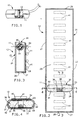
- Figure 1 shows a fuel tank partially cut away to show an internal liquid float gauge assembly according to the invention;
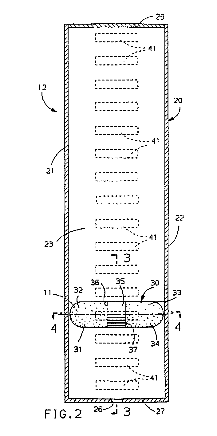
- Figure 2 shows an enlarged front cutaway view of a liquid float gauge assembly as used in the fuel tank of Figure 1;
- Figure 3 shows a view along lines 3-3 in Figure 2; and
- Figure 4 shows a view along lines 4-4 in Figure 2.
- Referring to Figure 1, a
fuel tank 10 of a motor vehicle comprises a liquid reservoir holding a variable amount ofliquid fuel 11. The level of fuel withinfuel tank 10 varies as fuel is added to or removed fromtank 10. In a predetermined location near the middle oftank 10, a liquidfloat gauge assembly 12 is supported vertically withintank 10. Normally, liquidfloat gauge assembly 12 is part of a total pump/gauge package, suspended from the top oftank 10, which also includes an in-tank fuel pump and a fuel inlet. However, only the liquidfloat gauge assembly 12 is shown. - Referring to Figure 2, liquid
float gauge assembly 12 includes avertical tube 20, made of substantially non-magnetic material, being of about 15 cm height and havingvertical side walls back wall 23 and, shown in Figures 3 and 4, afront wall 24. An opening 26 in afloor 27 oftube 20 provides damped liquid fuel communication between the interior oftube 20 and the remainder oftank 10. Openings, not shown, near thetop 29 oftube 20, may be included to provide air communication so that the air and vapour pressure over the liquid fuel intube 20 are essentially the same as those over theliquid fuel 11 intank 10outside tube 20. Thus, the liquid level intube 20 will be substantially the same as that withintank 10outside tube 20. The location oftube 20 is picked near the centre oftank 10 to minimize variations due to fuel sloshing during vehicle accelerations or operation on sloping ground. -
Tube 20 confines afloat 30, which is capsule shaped with an axially extended roundcylindrical portion 31 havingrounded ends major portion 34 made of a material such as nitrophenolic foam, which has a maximum specific gravity of 0.5 so as to float at the surface of aliquid fuel 11 such as gasoline. However, it further includes anannular magnet 35 forming essentially the axial centre of the outer surface offloat 30 and being magnetized with north and south poles at oppositeaxial ends Magnet 35 may be made ofnylon 12 or PPS-bonded strontium ferrite and may have an axial length of 0.8 cm and an annular thickness of 0.1 cm. As can be seen in Figure 4, the cross-sectional shaoe oftube 20 conforms to and is slightly larger than that offloat 30, so thatfloat 30 has a naturally stable orientation with a horizontal axis essentially at the liquid surface withintube 20. Iffloat 30 is upended withintube 20 for any reason, it will fall back to this stable horizontal position. In the context of this stability, the rounded ends 32 and 33 offloat 30 allow easier rotation back to the stable position. When thefloat 30 is horizontal, the confining shape and size oftube 20 maintainsfloat 30 in a predictable longitudinal and transverse position, as seen in Figure 4, while allowing vertical movement and rotation to the stable position as necessary. - A
circuit board 40 mounted adjacent and parallel toback wall 23 oftube 20 has mounted thereon a plurality ofreed switches 41 in a vertically spaced arrangement.Reed switches 41 are oriented, such as horizontally, so as to form a magnetic circuit withmagnet 35 when the latter is horizontally adjacent; and they are spaced vertically from each other so that only the closest is so activated. There are, for example, a minimum of 16such reed switches 41 spaced apart in, for example, a range of 0.953 to 0.825 cm. The size and shape oftube 20 as well as the shape offloat 30 and magnet orientation ofmagnet 35 therewithin provide a consistent relationship ofmagnet 35 toreed switches 41 asfloat 30 moves vertically and thus bringsmagnet 35 horizontally adjacent one or another ofreed switches 41. The magnetic attraction ofmagnet 35 to thereed switches 41 provides a bias onfloat 30 against the inner surface ofback wall 23 as well as a slight tendency to stay adjacent the reed switch which is currently closest. However, if the friction due to surface tension betweenfloat 30 andback wall 23 is small, the floating forces and/or weight offloat 30 withmagnet 35 will be sufficient to movefloat 30 up or down with the liquid surface. - Since
float 30 presents a round cylindrical surface toback wall 23, it is able to roll on that surface. The minimal tangential contact and the rolling action provide for minimal friction due to surface tension as thefloat 30 follows the changing liquid surface level; but the magnetic characteristics of theannular magnet 35 do not change as the float rolls.
Claims (3)
Applications Claiming Priority (2)
| Application Number | Priority Date | Filing Date | Title |
|---|---|---|---|
| US07/351,105 US4955231A (en) | 1989-05-12 | 1989-05-12 | Liquid float gage assembly |
| US351105 | 1999-07-06 |
Publications (2)
| Publication Number | Publication Date |
|---|---|
| EP0397338A1 true EP0397338A1 (en) | 1990-11-14 |
| EP0397338B1 EP0397338B1 (en) | 1993-09-01 |
Family
ID=23379596
Family Applications (1)
| Application Number | Title | Priority Date | Filing Date |
|---|---|---|---|
| EP90304295A Expired - Lifetime EP0397338B1 (en) | 1989-05-12 | 1990-04-20 | Liquid float gauge assembly |
Country Status (3)
| Country | Link |
|---|---|
| US (1) | US4955231A (en) |
| EP (1) | EP0397338B1 (en) |
| DE (1) | DE69003004T2 (en) |
Cited By (12)
| Publication number | Priority date | Publication date | Assignee | Title |
|---|---|---|---|---|
| EP0669523A1 (en) * | 1994-02-28 | 1995-08-30 | Sauermann Industrie | Device for detecting the liquid level in a container |
| EP0626568A3 (en) * | 1993-05-28 | 1996-01-31 | Simmonds Precision Products | Liquid gauge and remote interrogation sensor. |
| US5627380A (en) * | 1993-05-28 | 1997-05-06 | Simmonds Precision Products, Inc. | Fluid gauging apparatus using integral electrical sensor and a stick gauge |
| US5723870A (en) * | 1993-05-28 | 1998-03-03 | Simmonds Precision Products Inc. | Fluid gauging apparatus using magnetostrictive sensor and stick gauge |
| US5814830A (en) * | 1994-10-18 | 1998-09-29 | Simmonds Precision Products, Inc. | Liquid gauging apparatus with a magnetoresistive sensor and remote sensor interrogration |
| FR2797650A1 (en) * | 1999-08-18 | 2001-02-23 | Eparco Sa | Level detector e.g. for line between sludge and liquid in septic tank comprises float inside cage linked to indicator |
| RU2175387C2 (en) * | 1999-09-13 | 2001-10-27 | ОАО "Газпром" | Device to indicate level of fluid in borehole |
| WO2001059356A3 (en) * | 2000-02-11 | 2002-04-25 | Messer Griesheim Gmbh | Device for determining the filling level of liquefied gases in a cryogenic container |
| EP0938649A4 (en) * | 1996-10-24 | 2002-05-29 | Karl A Senghaas | Relative location detection sensor |
| RU2340878C1 (en) * | 2007-08-20 | 2008-12-10 | Федеральное государственное унитарное предприятие "Научно-исследовательский институт физических измерений" | Fluid level monitoring sensor |
| WO2013102658A1 (en) | 2012-01-06 | 2013-07-11 | Societe Technique Pour L'energie Atomique Technicatome | Liquid level sensor with free float |
| CN111238606A (en) * | 2020-03-18 | 2020-06-05 | 四川葛南仪器有限公司 | River water level monitor |
Families Citing this family (15)
| Publication number | Priority date | Publication date | Assignee | Title |
|---|---|---|---|---|
| US5299456A (en) * | 1992-06-30 | 1994-04-05 | Steiner George A | Electronic dipstick for indicating the oil level of an engine |
| GB2270758A (en) * | 1992-09-15 | 1994-03-23 | Platon A & I Limited | Apparatus for determining a parameter of a fluid |
| CA2179457C (en) * | 1996-06-19 | 2000-08-29 | George David Fraser | Method and apparatus for measuring a liquid level using a liquid level gauge having reed switches to determine the position of a magnetic float |
| US6408692B1 (en) * | 1997-11-20 | 2002-06-25 | Isspro, Inc. | Liquid level sensor |
| US6122955A (en) * | 1998-09-17 | 2000-09-26 | Hoog; Hollis Ellsworth | Liquid leak detector |
| KR100461127B1 (en) * | 2002-08-12 | 2004-12-13 | 현대자동차주식회사 | A fuel sender of a fuel tank for automobile |
| US7316541B2 (en) * | 2004-08-19 | 2008-01-08 | Black & Decker Inc. | Engine-powered air compressor with a controller for low oil condition |
| CN100338442C (en) * | 2005-04-22 | 2007-09-19 | 合肥邦立电子有限公司 | Oil box level sensor for vehicle |
| BRPI0622055A2 (en) * | 2006-10-16 | 2014-06-10 | Pricol Ltd | KEY TYPE FUEL SENSOR AND LOCKING ELECTROMALS |
| US8023848B2 (en) * | 2007-08-24 | 2011-09-20 | Seiko Epson Corporation | Density measuring device, liquid developer storing apparatus, and image forming apparatus |
| US8036555B2 (en) * | 2007-08-30 | 2011-10-11 | Seiko Epson Corporation | Liquid measuring device with floating member having magnetic field generators |
| US8549911B2 (en) * | 2008-05-29 | 2013-10-08 | Ilinois Tool Works Inc. | Multi-level liquid level magnetic sensor |
| USD654820S1 (en) | 2010-08-13 | 2012-02-28 | Isspro, Inc. | Fuel sender |
| TWI726944B (en) * | 2015-12-06 | 2021-05-11 | 美商應用材料股份有限公司 | Continuous liquid level measurement detector for closed metal containers |
| EP3887778B1 (en) | 2018-11-30 | 2023-01-11 | Carrier Corporation | Adaptable suppression tank level sensor |
Citations (3)
| Publication number | Priority date | Publication date | Assignee | Title |
|---|---|---|---|---|
| US4064755A (en) * | 1975-10-31 | 1977-12-27 | B/W Controls, Inc. | Liquid level sensor |
| US4259975A (en) * | 1979-04-09 | 1981-04-07 | Conoco, Inc. | Stock tank gauger-level controller |
| US4483193A (en) * | 1981-10-02 | 1984-11-20 | Cesare Bonetti S.P.A. | Magnetic level indicators |
Family Cites Families (5)
| Publication number | Priority date | Publication date | Assignee | Title |
|---|---|---|---|---|
| US2440987A (en) * | 1945-06-08 | 1948-05-04 | Amp Corp | Float switch |
| US2590680A (en) * | 1949-02-28 | 1952-03-25 | Julian A Campbell | Apparatus for liquid level controls |
| US2728227A (en) * | 1953-05-27 | 1955-12-27 | Gen Motors Corp | Magnetic liquid level indicators |
| US3224270A (en) * | 1963-02-12 | 1965-12-21 | Rca Corp | Flow gauges |
| DE3341265A1 (en) * | 1983-11-15 | 1985-05-23 | Phönix Armaturen-Werke Bregel GmbH, 6000 Frankfurt | MEASURING DEVICE |
-
1989
- 1989-05-12 US US07/351,105 patent/US4955231A/en not_active Expired - Fee Related
-
1990
- 1990-04-20 DE DE90304295T patent/DE69003004T2/en not_active Expired - Fee Related
- 1990-04-20 EP EP90304295A patent/EP0397338B1/en not_active Expired - Lifetime
Patent Citations (3)
| Publication number | Priority date | Publication date | Assignee | Title |
|---|---|---|---|---|
| US4064755A (en) * | 1975-10-31 | 1977-12-27 | B/W Controls, Inc. | Liquid level sensor |
| US4259975A (en) * | 1979-04-09 | 1981-04-07 | Conoco, Inc. | Stock tank gauger-level controller |
| US4483193A (en) * | 1981-10-02 | 1984-11-20 | Cesare Bonetti S.P.A. | Magnetic level indicators |
Cited By (16)
| Publication number | Priority date | Publication date | Assignee | Title |
|---|---|---|---|---|
| EP0626568A3 (en) * | 1993-05-28 | 1996-01-31 | Simmonds Precision Products | Liquid gauge and remote interrogation sensor. |
| US5530258A (en) * | 1993-05-28 | 1996-06-25 | Simmonds Precision Products, Inc. | Liquid gauging apparatus and remote sensor interrogation |
| US5627380A (en) * | 1993-05-28 | 1997-05-06 | Simmonds Precision Products, Inc. | Fluid gauging apparatus using integral electrical sensor and a stick gauge |
| US5723870A (en) * | 1993-05-28 | 1998-03-03 | Simmonds Precision Products Inc. | Fluid gauging apparatus using magnetostrictive sensor and stick gauge |
| FR2716715A1 (en) * | 1994-02-28 | 1995-09-01 | Sauermann Ind | Device for detecting liquid levels in a tank. |
| US5562003A (en) * | 1994-02-28 | 1996-10-08 | Sauermann Industrie | Apparatus for detecting the level of a liquid in a tank |
| EP0669523A1 (en) * | 1994-02-28 | 1995-08-30 | Sauermann Industrie | Device for detecting the liquid level in a container |
| US5814830A (en) * | 1994-10-18 | 1998-09-29 | Simmonds Precision Products, Inc. | Liquid gauging apparatus with a magnetoresistive sensor and remote sensor interrogration |
| EP0938649A4 (en) * | 1996-10-24 | 2002-05-29 | Karl A Senghaas | Relative location detection sensor |
| FR2797650A1 (en) * | 1999-08-18 | 2001-02-23 | Eparco Sa | Level detector e.g. for line between sludge and liquid in septic tank comprises float inside cage linked to indicator |
| RU2175387C2 (en) * | 1999-09-13 | 2001-10-27 | ОАО "Газпром" | Device to indicate level of fluid in borehole |
| WO2001059356A3 (en) * | 2000-02-11 | 2002-04-25 | Messer Griesheim Gmbh | Device for determining the filling level of liquefied gases in a cryogenic container |
| RU2340878C1 (en) * | 2007-08-20 | 2008-12-10 | Федеральное государственное унитарное предприятие "Научно-исследовательский институт физических измерений" | Fluid level monitoring sensor |
| WO2013102658A1 (en) | 2012-01-06 | 2013-07-11 | Societe Technique Pour L'energie Atomique Technicatome | Liquid level sensor with free float |
| FR2985566A1 (en) * | 2012-01-06 | 2013-07-12 | Technicatome | LIQUID LEVEL SENSOR WITH FREE FLOAT |
| CN111238606A (en) * | 2020-03-18 | 2020-06-05 | 四川葛南仪器有限公司 | River water level monitor |
Also Published As
| Publication number | Publication date |
|---|---|
| US4955231A (en) | 1990-09-11 |
| DE69003004T2 (en) | 1993-12-16 |
| EP0397338B1 (en) | 1993-09-01 |
| DE69003004D1 (en) | 1993-10-07 |
Similar Documents
| Publication | Publication Date | Title |
|---|---|---|
| EP0397338B1 (en) | Liquid float gauge assembly | |
| US5780741A (en) | Sensor employing a sliding magnet suspended on ferrofluid | |
| US5908987A (en) | Sensor employing a sliding ferrofluid mass in a coated, non-wetting, housing | |
| US3992941A (en) | Liquid level measuring apparatus | |
| EP0897527B1 (en) | Improvements in magnetic float type liquid level gauges | |
| US4457171A (en) | Liquid-level indicator | |
| US6584838B2 (en) | Angular position sensor | |
| US6813946B1 (en) | Liquid sensing | |
| US20080047154A1 (en) | Inclination sensor | |
| JPH02116719A (en) | Magnetic float for magnetic sensor | |
| US5054318A (en) | Resonance frequency liquid level sensor | |
| US4090050A (en) | Electro-mechanical liquid level sensor | |
| US3151488A (en) | Angular accelerometer | |
| CA2637497A1 (en) | Liquid level and density measurement device | |
| KR100519138B1 (en) | Magnetic float type liquid level display device | |
| JP6014836B2 (en) | Float type liquid level detector | |
| KR950002978B1 (en) | Air bag accumulator with movable cup shape sensor | |
| EP0124401B1 (en) | A fluid level indicator | |
| WO2006061232A1 (en) | Fluid level measurement apparatus | |
| KR960013253B1 (en) | Fluid level meter | |
| SU1700380A1 (en) | Liquid level indicator | |
| JPH0232219A (en) | Level gauge using magnetic detector | |
| US5661238A (en) | Bi-stable liquid indicator | |
| JPH0455266B2 (en) | ||
| SU823891A2 (en) | Vibration threshold pickup |
Legal Events
| Date | Code | Title | Description |
|---|---|---|---|
| PUAI | Public reference made under article 153(3) epc to a published international application that has entered the european phase |
Free format text: ORIGINAL CODE: 0009012 |
|
| AK | Designated contracting states |
Kind code of ref document: A1 Designated state(s): DE FR GB |
|
| 17P | Request for examination filed |
Effective date: 19901109 |
|
| 17Q | First examination report despatched |
Effective date: 19920408 |
|
| GRAA | (expected) grant |
Free format text: ORIGINAL CODE: 0009210 |
|
| AK | Designated contracting states |
Kind code of ref document: B1 Designated state(s): DE FR GB |
|
| REF | Corresponds to: |
Ref document number: 69003004 Country of ref document: DE Date of ref document: 19931007 |
|
| ET | Fr: translation filed | ||
| PGFP | Annual fee paid to national office [announced via postgrant information from national office to epo] |
Ref country code: GB Payment date: 19940331 Year of fee payment: 5 |
|
| PGFP | Annual fee paid to national office [announced via postgrant information from national office to epo] |
Ref country code: FR Payment date: 19940428 Year of fee payment: 5 |
|
| PGFP | Annual fee paid to national office [announced via postgrant information from national office to epo] |
Ref country code: DE Payment date: 19940613 Year of fee payment: 5 |
|
| PLBE | No opposition filed within time limit |
Free format text: ORIGINAL CODE: 0009261 |
|
| STAA | Information on the status of an ep patent application or granted ep patent |
Free format text: STATUS: NO OPPOSITION FILED WITHIN TIME LIMIT |
|
| 26N | No opposition filed | ||
| PG25 | Lapsed in a contracting state [announced via postgrant information from national office to epo] |
Ref country code: GB Effective date: 19950420 |
|
| GBPC | Gb: european patent ceased through non-payment of renewal fee |
Effective date: 19950420 |
|
| PG25 | Lapsed in a contracting state [announced via postgrant information from national office to epo] |
Ref country code: FR Effective date: 19951229 |
|
| PG25 | Lapsed in a contracting state [announced via postgrant information from national office to epo] |
Ref country code: DE Effective date: 19960103 |
|
| REG | Reference to a national code |
Ref country code: FR Ref legal event code: ST |