EP0396121B1 - A system for coding wide-band audio signals - Google Patents
A system for coding wide-band audio signals Download PDFInfo
- Publication number
- EP0396121B1 EP0396121B1 EP90108332A EP90108332A EP0396121B1 EP 0396121 B1 EP0396121 B1 EP 0396121B1 EP 90108332 A EP90108332 A EP 90108332A EP 90108332 A EP90108332 A EP 90108332A EP 0396121 B1 EP0396121 B1 EP 0396121B1
- Authority
- EP
- European Patent Office
- Prior art keywords
- signal
- long
- lag
- term analysis
- excitation
- Prior art date
- Legal status (The legal status is an assumption and is not a legal conclusion. Google has not performed a legal analysis and makes no representation as to the accuracy of the status listed.)
- Expired - Lifetime
Links
- 230000005236 sound signal Effects 0.000 title claims description 25
- 230000007774 longterm Effects 0.000 claims description 103
- 238000004458 analytical method Methods 0.000 claims description 98
- 230000005284 excitation Effects 0.000 claims description 96
- 239000013598 vector Substances 0.000 claims description 80
- 238000003786 synthesis reaction Methods 0.000 claims description 56
- 238000000034 method Methods 0.000 claims description 48
- 230000015572 biosynthetic process Effects 0.000 claims description 42
- 230000006870 function Effects 0.000 claims description 40
- 238000012545 processing Methods 0.000 claims description 27
- 238000001914 filtration Methods 0.000 claims description 18
- 238000012546 transfer Methods 0.000 claims description 16
- 230000005540 biological transmission Effects 0.000 claims description 13
- 238000013139 quantization Methods 0.000 claims description 11
- 238000005070 sampling Methods 0.000 claims description 10
- 238000001228 spectrum Methods 0.000 claims description 10
- 238000007493 shaping process Methods 0.000 claims description 9
- 101000972841 Lens culinaris Non-specific lipid-transfer protein 4 Proteins 0.000 claims description 8
- 230000015654 memory Effects 0.000 claims description 8
- 101000578200 Lens culinaris Non-specific lipid-transfer protein 6 Proteins 0.000 claims description 7
- 101000578195 Lens culinaris Non-specific lipid-transfer protein 5 Proteins 0.000 claims description 6
- 101150029874 cmb1 gene Proteins 0.000 claims description 5
- 101100060402 Dianthus caryophyllus CMB2 gene Proteins 0.000 claims description 4
- 230000003595 spectral effect Effects 0.000 description 8
- 230000003044 adaptive effect Effects 0.000 description 6
- 238000010586 diagram Methods 0.000 description 5
- 230000000007 visual effect Effects 0.000 description 4
- 101000605019 Lachesana tarabaevi M-zodatoxin-Lt1a Proteins 0.000 description 3
- 230000008569 process Effects 0.000 description 3
- 101100406317 Arabidopsis thaliana BCE2 gene Proteins 0.000 description 2
- 101710196810 Non-specific lipid-transfer protein 2 Proteins 0.000 description 2
- 238000006243 chemical reaction Methods 0.000 description 2
- 101000822695 Clostridium perfringens (strain 13 / Type A) Small, acid-soluble spore protein C1 Proteins 0.000 description 1
- 101000655262 Clostridium perfringens (strain 13 / Type A) Small, acid-soluble spore protein C2 Proteins 0.000 description 1
- 101000972854 Lens culinaris Non-specific lipid-transfer protein 3 Proteins 0.000 description 1
- 101000655256 Paraclostridium bifermentans Small, acid-soluble spore protein alpha Proteins 0.000 description 1
- 101000655264 Paraclostridium bifermentans Small, acid-soluble spore protein beta Proteins 0.000 description 1
- 230000015556 catabolic process Effects 0.000 description 1
- 238000006731 degradation reaction Methods 0.000 description 1
- 230000001419 dependent effect Effects 0.000 description 1
- 230000000694 effects Effects 0.000 description 1
- 238000012986 modification Methods 0.000 description 1
- 230000004048 modification Effects 0.000 description 1
- 238000010606 normalization Methods 0.000 description 1
- 230000009467 reduction Effects 0.000 description 1
- 230000001755 vocal effect Effects 0.000 description 1
Images


Classifications
-
- H—ELECTRICITY
- H04—ELECTRIC COMMUNICATION TECHNIQUE
- H04B—TRANSMISSION
- H04B1/00—Details of transmission systems, not covered by a single one of groups H04B3/00 - H04B13/00; Details of transmission systems not characterised by the medium used for transmission
- H04B1/66—Details of transmission systems, not covered by a single one of groups H04B3/00 - H04B13/00; Details of transmission systems not characterised by the medium used for transmission for reducing bandwidth of signals; for improving efficiency of transmission
- H04B1/667—Details of transmission systems, not covered by a single one of groups H04B3/00 - H04B13/00; Details of transmission systems not characterised by the medium used for transmission for reducing bandwidth of signals; for improving efficiency of transmission using a division in frequency subbands
-
- G—PHYSICS
- G10—MUSICAL INSTRUMENTS; ACOUSTICS
- G10L—SPEECH ANALYSIS TECHNIQUES OR SPEECH SYNTHESIS; SPEECH RECOGNITION; SPEECH OR VOICE PROCESSING TECHNIQUES; SPEECH OR AUDIO CODING OR DECODING
- G10L19/00—Speech or audio signals analysis-synthesis techniques for redundancy reduction, e.g. in vocoders; Coding or decoding of speech or audio signals, using source filter models or psychoacoustic analysis
- G10L19/002—Dynamic bit allocation
-
- G—PHYSICS
- G10—MUSICAL INSTRUMENTS; ACOUSTICS
- G10L—SPEECH ANALYSIS TECHNIQUES OR SPEECH SYNTHESIS; SPEECH RECOGNITION; SPEECH OR VOICE PROCESSING TECHNIQUES; SPEECH OR AUDIO CODING OR DECODING
- G10L19/00—Speech or audio signals analysis-synthesis techniques for redundancy reduction, e.g. in vocoders; Coding or decoding of speech or audio signals, using source filter models or psychoacoustic analysis
- G10L19/02—Speech or audio signals analysis-synthesis techniques for redundancy reduction, e.g. in vocoders; Coding or decoding of speech or audio signals, using source filter models or psychoacoustic analysis using spectral analysis, e.g. transform vocoders or subband vocoders
- G10L19/0204—Speech or audio signals analysis-synthesis techniques for redundancy reduction, e.g. in vocoders; Coding or decoding of speech or audio signals, using source filter models or psychoacoustic analysis using spectral analysis, e.g. transform vocoders or subband vocoders using subband decomposition
-
- G—PHYSICS
- G10—MUSICAL INSTRUMENTS; ACOUSTICS
- G10L—SPEECH ANALYSIS TECHNIQUES OR SPEECH SYNTHESIS; SPEECH RECOGNITION; SPEECH OR VOICE PROCESSING TECHNIQUES; SPEECH OR AUDIO CODING OR DECODING
- G10L19/00—Speech or audio signals analysis-synthesis techniques for redundancy reduction, e.g. in vocoders; Coding or decoding of speech or audio signals, using source filter models or psychoacoustic analysis
- G10L19/04—Speech or audio signals analysis-synthesis techniques for redundancy reduction, e.g. in vocoders; Coding or decoding of speech or audio signals, using source filter models or psychoacoustic analysis using predictive techniques
- G10L19/08—Determination or coding of the excitation function; Determination or coding of the long-term prediction parameters
- G10L19/10—Determination or coding of the excitation function; Determination or coding of the long-term prediction parameters the excitation function being a multipulse excitation
- G10L19/113—Regular pulse excitation
-
- G—PHYSICS
- G10—MUSICAL INSTRUMENTS; ACOUSTICS
- G10L—SPEECH ANALYSIS TECHNIQUES OR SPEECH SYNTHESIS; SPEECH RECOGNITION; SPEECH OR VOICE PROCESSING TECHNIQUES; SPEECH OR AUDIO CODING OR DECODING
- G10L19/00—Speech or audio signals analysis-synthesis techniques for redundancy reduction, e.g. in vocoders; Coding or decoding of speech or audio signals, using source filter models or psychoacoustic analysis
- G10L19/04—Speech or audio signals analysis-synthesis techniques for redundancy reduction, e.g. in vocoders; Coding or decoding of speech or audio signals, using source filter models or psychoacoustic analysis using predictive techniques
- G10L19/08—Determination or coding of the excitation function; Determination or coding of the long-term prediction parameters
- G10L19/12—Determination or coding of the excitation function; Determination or coding of the long-term prediction parameters the excitation function being a code excitation, e.g. in code excited linear prediction [CELP] vocoders
-
- G—PHYSICS
- G10—MUSICAL INSTRUMENTS; ACOUSTICS
- G10L—SPEECH ANALYSIS TECHNIQUES OR SPEECH SYNTHESIS; SPEECH RECOGNITION; SPEECH OR VOICE PROCESSING TECHNIQUES; SPEECH OR AUDIO CODING OR DECODING
- G10L19/00—Speech or audio signals analysis-synthesis techniques for redundancy reduction, e.g. in vocoders; Coding or decoding of speech or audio signals, using source filter models or psychoacoustic analysis
- G10L2019/0001—Codebooks
- G10L2019/0011—Long term prediction filters, i.e. pitch estimation
-
- G—PHYSICS
- G10—MUSICAL INSTRUMENTS; ACOUSTICS
- G10L—SPEECH ANALYSIS TECHNIQUES OR SPEECH SYNTHESIS; SPEECH RECOGNITION; SPEECH OR VOICE PROCESSING TECHNIQUES; SPEECH OR AUDIO CODING OR DECODING
- G10L19/00—Speech or audio signals analysis-synthesis techniques for redundancy reduction, e.g. in vocoders; Coding or decoding of speech or audio signals, using source filter models or psychoacoustic analysis
- G10L2019/0001—Codebooks
- G10L2019/0013—Codebook search algorithms
- G10L2019/0014—Selection criteria for distances
-
- G—PHYSICS
- G10—MUSICAL INSTRUMENTS; ACOUSTICS
- G10L—SPEECH ANALYSIS TECHNIQUES OR SPEECH SYNTHESIS; SPEECH RECOGNITION; SPEECH OR VOICE PROCESSING TECHNIQUES; SPEECH OR AUDIO CODING OR DECODING
- G10L25/00—Speech or voice analysis techniques not restricted to a single one of groups G10L15/00 - G10L21/00
- G10L25/03—Speech or voice analysis techniques not restricted to a single one of groups G10L15/00 - G10L21/00 characterised by the type of extracted parameters
- G10L25/06—Speech or voice analysis techniques not restricted to a single one of groups G10L15/00 - G10L21/00 characterised by the type of extracted parameters the extracted parameters being correlation coefficients
Definitions
- the present invention concerns audio signal coding systems, and more particularly a system for coding wide-band audio signals.
- wide-band audio signals is used to indicate audio signals whose bandwidth is wider than the conventional 3.4 kHz telephone band, and more particularly signals with a bandwidth of the order of 7 kHz.
- such a low bit rate coding of audio signals provides larger band availability for non-audio transmissions, such as facsimile, which may accompany audio signal transmission.
- CITT recommendation G 722 An international standard exists (CCITT recommendation G 722) for coding 7 kHz audio signals, which describes a system for coding such signals at bit rates of 48, 56 or 64 kbit/s.
- a coding system substantially similar to that proposed by said recommendation is described in the paper entitled “Digital Transmission of Commentary Grade (7 kHz) Audio at 56 or 64 kbit/s.” by J. D.Johnston and D. J. Goodman, IEEE Transactions on Communications, Vol COM-28, No. 1, January 1980. In that system the signal to be coded is split into two sub-bands, the lower up to 3650 Hz and the upper from 3600 to 6800 Hz.
- the lower sub-band is coded with 4 bit/sample ADPCM (Adaptive Differential Pulse Code Modulation) and the upper one with 3 bit/sample or 4 bit/sample APCM (Adaptive Pulse Code Modulation), depending on whether 56 kbit/s or 64 kbit/s transmission rate is desired.
- ADPCM Adaptive Differential Pulse Code Modulation
- APCM Adaptive Pulse Code Modulation
- the pitch predictor parameters may be determined either in an open loop configuration or in a closed loop configuration. No configuration is known from this document which is intermediate between the open loop and the closed loop configurations.
- APC-AB adaptive predictive coding with adaptive bit allocation
- the processing of wide-band signals is not possible with said method.
- the synthesis technique is not a technique in which the excitation signal for the synthesis filter simulating the vocal tract at the decoder is chosen in such a manner as to minimize a perceptually significant distortion measure.
- the invention provides on the contrary a coding method and device in which the sub-band structure (e.g. with 2 sub-bands) is maintained and each sub-band is coded according to a technique ensuring a higher coding gain at the bit rates of interest and hence ensuring the quality satisfying visual telephony and audioconference requirements.
- the sub-band structure e.g. with 2 sub-bands
- a method of coding audio signals comprising the steps of: converting the signal to be coded into digital form, filtering the digital signal so as to split the total band into at least two sub-bands, organizing the signals of each sub-band into frames comprising a predetermined number of samples, coding the signals of each sub-band independently of those of the other sub-bands, and sending the coded signals onto a transmission line for transmission at medium bit rate, is characterized in that the signals to be coded and to be split into the sub-bands are wide-band audio signals; and the signals of each sub-band are coded according to an analysis-by-synthesis technique in which the excitation signal is chosen out of a codebook of vectors (codebook excited linear prediction technique) and in which a short term analysis of the signal to be coded is effected to determine a set of linear prediction coefficients and a long term analysis is effected to determine a long-term analysis lag (pitch period) and a long-term analysis gain, the coded signals thus containing quantized information relevant to the ex
- the invention also concerns a device for implementing the method, comprising: means for sampling the signal to be coded at a first sampling frequency which is a multiple of the maximum frequency of said signal, means for filtering the sampled signal so as to split its band into adjacent sub-bands, means for sampling the signals of each sub-band at their respective Nyquist frequency, coders for digitally coding the sampled signals of each sub-band, and means for sending the coded signals relevant to each sub-band onto a transmission line onto which the coded audio signals are transmitted at medium bit rate;
- each coder is an analysis-by-synthesis coder in which the excitation signal is chosen out of a codebook of vectors (codebook excited linear prediction technique) and includes means for effecting a short-term and a long-term analysis of the audio signal of the respective sub-band and for determining an excitation signal for reproducing each one of subsequent portions of said audio signal, the coded signal including quantized information relevant to the
- the means for short-term analysis are connected to a circuit for split-codebook vector quantization of adjacent spectrum line pairs, or of differences between adjacent spectrum lines, obtained as a representation of linear prediction coefficients determined by the short-term analysis.
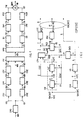
- a 7 kHz audio signal present on a line 100 and obtained by suitable analog filtering in filters not shown, is fed to a first sampler CM0, operating e.g. at 16 kHz, whose output 101 is connected to two filters FQ1, FQ2 one of which (namely FQ1) is a high-pass filter whilst the other is a low-pass filter.
- Said two filters which have the same bandwidth, can advantageously be of the type known as QMF (Quadrature Mirror Filter), apt to let through half the band admitted by the sampling frequency.
- QMF Quadrature Mirror Filter
- the signals present on outputs 102, 103 of filters FQ1, FQ2, relevant to the upper and the lower sub-band respectively, are supplied to samplers CM1, CM2, operating at the Nyquist frequency for such signals, i.e. 8 kHz if sampler CM0 operates at 16 kHz.
- the samples thus obtained, organized into frames of convenient duration, e.g. 15 or 20 ms, are supplied, through connections 104, 105, to coders CD1, CD2, operating according to analysis-by-synthesis techniques.
- the coded signals, present on connections 106, 107, are sent onto transmission line 109 through devices, which are schematically represented by multiplexer MX, allowing transmission on line 109 also of non-speech signals, if any, present on a connection 108.
- a demultiplexer DMX sends the speech signals, via connections 110, 111, to decoders D1, D2, reconstructing the signals of the two sub-bands. Processing of non-speech signal is of no interest to this invention and hence the devices carrying out such processing are not shown.
- Outputs 112, 113 of D1, D2 are connected to respective interpolators IN1, IN2, reconstructing the 16 kHz signals.
- Outputs 114, 115 of said interpolators are connected to filters FQ3, FQ4, analogous to filters FQ1 and FQ2, eliminating aliasing distortion in the interpolated signals.
- the filtered signals relevant to the two sub-bands, present on connections 116, 117, are then recombined into a signal with the same band as the original signal (as schematically represented by adder SOM), and sent through a line 118 to utilizing devices.
- the first solution allows higher-modularity coders to be implemented; a solution of this kind is obviously preferred when the signals to be coded present substantially the same characteristics in both sub-bands.
- the second and third solutions still starting from quite general remarks, exploit the knowledge of the characteristics of the signals to be coded, and the dependence on such characteristics is maximum in the third solution: the resulting coders will hence present optimum performance for a particular signal and are suitable for different cases from those which can be faced by the first solution.
- each sample frame of each sub-band is allotted a bit rate ensuring uniform distortion in the frame, such rate being variable from a frame to the subsequent one.
- multi-pulse excitation linear prediction the already-cited CELP
- VAPC Vectorial Adaptive Predictive Coding
- RPE/LTP Regular Pulse Excited [coding with] Long Term Prediction
- VADPCM Vectorial Adaptive Differential Pulse Code Modulation
- coders CD1 and CD2 can be implemented and can operate as described in European Patent Application No. 89117837.8 filed on 27.09.1989, entitled "Method of and device for speech signal coding and decoding by means of a multipulse excitation".
- the method described in that application comprises a coding phase including the following operations:
- the lag and the gain are determined in two successive steps, in the first of which the lag is determined by minimizing the mean squared error between the residual signal and a signal which is the signal resulting from said long-term synthesis filtering with null input, if the synthesis relevant to a sample of the current frame is performed on the basis of a sample of a preceding frame, and is said residual signal if the synthesis relevant to a sample of the current frame is performed on the basis of a preceding sample of the same frame, while in the second step the gain is calculated with the following sequence of operations: a value of said further signal is determined for a unitary gain value; a first error value is hence determined, and the operations for determining the value of the signal weighted with said second weighting function and of the error are repeated for each value possible for the gain, the value adopted being the one which minimizes the error.
- the device implementing the above described method comprises, for speech signal coding:
- Figs. 2 and 3 which correspond with Figs. 1 and 3 of the above-mentioned European Patent Application.
- the conversion means are not shown in Fig. 2, since they are external to the actual coder and are circuits CM1, CM2 of Fig. 1.
- long-term analysis circuit LTA1 receives only the spectrally-shaped signal s w (n) and the quantized linear predictions coefficients â(k), and computes only lag M optimizing its value taking into account the analyses and syntheses previously performed.
- Lag M is sent to coder LTC1 via connection 207.
- Excitation generator EG1 determines an optimum excitation model, consisting of a sequence of vectors e(i) (innovation), the corresponding gain or scale factor g(i), and gain B by which the preceding samples are weighted during long-term analysis relevant to the current sample.
- Gain B is sent to coder LTC1 via connection 212; a coder IGC receives from EG1 and codes indices i of the vectors of the optimum excitation model and scale factors g(i).
- the codebook becomes exhaustive as it comprises all permutations of two pulses (of unitary absolute value) within a vector of P elements.
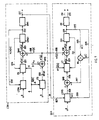
- Fig. 5 shows a possible embodiment of blocks LTA1, EG1 of Fig. 4.
- the problem is to minimize, in a perceptually meaningful way, the mean squared error between the original signal and the reconstructed one.
- the optimum solution would be that of jointly determining the combination of innovation (vector and relevant gain), long-term analysis gain and long-term analysis lag which minimizes such an error.
- the optimum solution is too complex and hence, according to the invention, the computation of M is separated from the determination of the excitation (gain B of long-term analysis, vectors e(i), scale factor g(i) of said vectors).
- the minimization uses samples s1(p) of a signal s1 obtained as difference between samples s w (p) of the spectrally-shaped signal and samples s0(p) of a signal s0 obtained by weighting a null signal with the same function 1/A(z, ⁇ ) used during speech signal spectral shaping.
- Signal s0 represents the contribution of the preceding analyses and syntheses.
- Samples s1(p) are present on output 208 of an adder SM3 which has an input connected to connection 3 conveying spectrally-shaped signal s w , and another input connected to output 220 of a filter F5 which generates signal s0.
- Lag value M which minimizes ds1 is stored in a register RM1 for the whole validity period of long-term analysis parameters (e.g. 2,5 ms with the frame duration and the number of vectors stated above) and is kept available on connection 207.
- Signal s4(p) is present on output 225 of a weighting filter F7, analogous to F6: filter F7 weights by function 1/A(z, ⁇ ) the signal present on output 226 of an adder SM5, combining into a single signal the contributions given to excitation by the innovation and the long-term analysis.
- the first contribution is present on output 227 of a multiplier M1, which multiplies the excitation vectors e(i) by a scale factor g(i).
- the second contribution is present on output 228 of a long-term synthesis filter LTP5, analogous to LTP4, which also is fed with a null signal.
- LTP5 operates with lag M determined in the first step and, for each excitation vector e(i), with value b(i) of long-term analysis gain which is the optimum value for that vector.
- Values b , vectors e(i) and scale factors g are supplied to LTP5 and M1 via connection 229 by a processing unit CE1 executing the mathematical operations necessary to minimize ds2.
- the memory of F7 is reset by CE1 at every new excitation, as schematized by connection 231.
- the various elements of the optimum excitation model are then stored in registers denoted as a whole by RE and kept available for coders LTC1, IGC (Fig. 4).
- signal s1(p) is used to determine M as in the embodiment of Fig. 5 and a mean squared error is minimized, by imposing that the lag be always higher than vector length P.
- filter LTP6 successively receives from a processing unit CMB2, analogous to CMB1, all possible values m of the lag (connection 322a). Yet no weighting of the samples with gain b is effected inside the filter, this weighting being effected, in correspondence with each value m , by a multiplier M2 which receives from CMB2 optimum value b(m) relevant to that value m . That optimum value is implicitly determined during the computations relevant to minimization and is fed to M2 through connection 322b, OR gate PR1 and connection 322c. Value M minimizing ds3 is then rendered available on connection 207 through a register RM2, identical to RM1 (Fig. 5).
- Signal s7(i, p) is signal s7 when the lag used in LTP6 is actually lag M and multiplying factor in M2 is a value b(i) of long-term analysis gain which is the optimum gain for that vector e(i).
- M2 is supplied by CE2 with value b(i) through connection 329 and gate PR1.
- filters F8, F9 are reset by processing units CMB2, CE2 (connections 324, 331) at each new value m of long-term analysis lag or at each new excitation, respectively.
Landscapes
- Engineering & Computer Science (AREA)
- Signal Processing (AREA)
- Physics & Mathematics (AREA)
- Computational Linguistics (AREA)
- Health & Medical Sciences (AREA)
- Audiology, Speech & Language Pathology (AREA)
- Human Computer Interaction (AREA)
- Acoustics & Sound (AREA)
- Multimedia (AREA)
- Computer Networks & Wireless Communication (AREA)
- Spectroscopy & Molecular Physics (AREA)
- Compression, Expansion, Code Conversion, And Decoders (AREA)
Applications Claiming Priority (2)
| Application Number | Priority Date | Filing Date | Title |
|---|---|---|---|
| IT8967317A IT1232084B (it) | 1989-05-03 | 1989-05-03 | Sistema di codifica per segnali audio a banda allargata |
| IT6731789 | 1989-05-03 |
Publications (2)
| Publication Number | Publication Date |
|---|---|
| EP0396121A1 EP0396121A1 (en) | 1990-11-07 |
| EP0396121B1 true EP0396121B1 (en) | 1996-09-11 |
Family
ID=11301410
Family Applications (1)
| Application Number | Title | Priority Date | Filing Date |
|---|---|---|---|
| EP90108332A Expired - Lifetime EP0396121B1 (en) | 1989-05-03 | 1990-05-02 | A system for coding wide-band audio signals |
Country Status (4)
| Country | Link |
|---|---|
| EP (1) | EP0396121B1 (it) |
| CA (1) | CA2016042C (it) |
| DE (2) | DE69028434T2 (it) |
| IT (1) | IT1232084B (it) |
Families Citing this family (16)
| Publication number | Priority date | Publication date | Assignee | Title |
|---|---|---|---|---|
| US5754976A (en) * | 1990-02-23 | 1998-05-19 | Universite De Sherbrooke | Algebraic codebook with signal-selected pulse amplitude/position combinations for fast coding of speech |
| DE69229974T2 (de) * | 1991-02-26 | 2000-07-20 | Nec Corp., Tokio/Tokyo | Verfahren und Vorrichtung zur Kodierung von Sprachparametern |
| IT1257065B (it) * | 1992-07-31 | 1996-01-05 | Sip | Codificatore a basso ritardo per segnali audio, utilizzante tecniche di analisi per sintesi. |
| US5717824A (en) * | 1992-08-07 | 1998-02-10 | Pacific Communication Sciences, Inc. | Adaptive speech coder having code excited linear predictor with multiple codebook searches |
| IT1257431B (it) * | 1992-12-04 | 1996-01-16 | Sip | Procedimento e dispositivo per la quantizzazione dei guadagni dell'eccitazione in codificatori della voce basati su tecniche di analisi per sintesi |
| BE1007617A3 (nl) * | 1993-10-11 | 1995-08-22 | Philips Electronics Nv | Transmissiesysteem met gebruik van verschillende codeerprincipes. |
| US5506908A (en) * | 1994-06-30 | 1996-04-09 | At&T Corp. | Directional microphone system |
| JPH09506478A (ja) * | 1994-10-06 | 1997-06-24 | フィリップス エレクトロニクス ネムローゼ フェンノートシャップ | 光放射半導体ダイオード及びこのようなダイオードの製造方法 |
| JP2842276B2 (ja) * | 1995-02-24 | 1998-12-24 | 日本電気株式会社 | 広帯域信号符号化装置 |
| TW321810B (it) * | 1995-10-26 | 1997-12-01 | Sony Co Ltd | |
| FI114248B (fi) * | 1997-03-14 | 2004-09-15 | Nokia Corp | Menetelmä ja laite audiokoodaukseen ja audiodekoodaukseen |
| GB2326572A (en) * | 1997-06-19 | 1998-12-23 | Softsound Limited | Low bit rate audio coder and decoder |
| JP3199020B2 (ja) * | 1998-02-27 | 2001-08-13 | 日本電気株式会社 | 音声音楽信号の符号化装置および復号装置 |
| FI113571B (fi) | 1998-03-09 | 2004-05-14 | Nokia Corp | Puheenkoodaus |
| RU2393552C2 (ru) * | 2004-09-17 | 2010-06-27 | Конинклейке Филипс Электроникс Н.В. | Комбинированное аудиокодирование, минимизирующее воспринимаемое искажение |
| WO2010003521A1 (en) * | 2008-07-11 | 2010-01-14 | Fraunhofer-Gesellschaft zur Förderung der angewandten Forschung e.V. | Method and discriminator for classifying different segments of a signal |
Family Cites Families (3)
| Publication number | Priority date | Publication date | Assignee | Title |
|---|---|---|---|---|
| JPS5921039B2 (ja) * | 1981-11-04 | 1984-05-17 | 日本電信電話株式会社 | 適応予測符号化方式 |
| EP0111612B1 (fr) * | 1982-11-26 | 1987-06-24 | International Business Machines Corporation | Procédé et dispositif de codage d'un signal vocal |
| DE3688980T2 (de) * | 1986-10-30 | 1994-04-21 | Ibm | Verfahren zur Multigeschwindigkeitskodierung von Signalen und Einrichtung zur Durchführung dieses Verfahrens. |
-
1989
- 1989-05-03 IT IT8967317A patent/IT1232084B/it active
-
1990
- 1990-05-02 DE DE69028434T patent/DE69028434T2/de not_active Expired - Lifetime
- 1990-05-02 DE DE199090108332T patent/DE396121T1/de active Pending
- 1990-05-02 EP EP90108332A patent/EP0396121B1/en not_active Expired - Lifetime
- 1990-05-03 CA CA002016042A patent/CA2016042C/en not_active Expired - Lifetime
Also Published As
| Publication number | Publication date |
|---|---|
| EP0396121A1 (en) | 1990-11-07 |
| DE396121T1 (de) | 1991-03-21 |
| DE69028434D1 (de) | 1996-10-17 |
| IT1232084B (it) | 1992-01-23 |
| IT8967317A0 (it) | 1989-05-03 |
| DE69028434T2 (de) | 1997-02-20 |
| CA2016042C (en) | 1998-04-28 |
| CA2016042A1 (en) | 1990-11-03 |
Similar Documents
| Publication | Publication Date | Title |
|---|---|---|
| US5321793A (en) | Low-delay audio signal coder, using analysis-by-synthesis techniques | |
| JP3996213B2 (ja) | 入力標本列処理方法 | |
| EP0770989B1 (en) | Speech encoding method and apparatus | |
| EP0331858B1 (en) | Multi-rate voice encoding method and device | |
| US6401062B1 (en) | Apparatus for encoding and apparatus for decoding speech and musical signals | |
| JP4662673B2 (ja) | 広帯域音声及びオーディオ信号復号器における利得平滑化 | |
| EP0772186B1 (en) | Speech encoding method and apparatus | |
| US5602961A (en) | Method and apparatus for speech compression using multi-mode code excited linear predictive coding | |
| JP3566652B2 (ja) | 広帯域信号の効率的な符号化のための聴覚重み付け装置および方法 | |
| US5491771A (en) | Real-time implementation of a 8Kbps CELP coder on a DSP pair | |
| EP0396121A1 (en) | A system for coding wide-band audio signals | |
| US20010027393A1 (en) | Method of and apparatus for processing at least one coded binary audio flux organized into frames | |
| JPH02123828A (ja) | サブバンドコーディング方法および装置 | |
| EP0411655B1 (en) | Vector quantization encoder and vector quantization decoder | |
| GB2323759A (en) | Audio coding and decoding with compression | |
| JPS6161305B2 (it) | ||
| KR19980024885A (ko) | 벡터양자화 방법, 음성부호화 방법 및 장치 | |
| KR19980024519A (ko) | 벡터양자화 방법, 음성부호화 방법 및 장치 | |
| JPWO2001020595A1 (ja) | 音声符号化及び音声復号化装置 | |
| AU711082B2 (en) | Methods of and apparatus for coding discrete signals and decoding coded discrete signals, respectively | |
| WO1999018565A2 (en) | Speech coding | |
| EP0801377B1 (en) | Apparatus for coding a signal | |
| US5926785A (en) | Speech encoding method and apparatus including a codebook storing a plurality of code vectors for encoding a speech signal | |
| WO2000017858A1 (en) | Robust fast search for two-dimensional gain vector quantizer | |
| EP0361432B1 (en) | Method of and device for speech signal coding and decoding by means of a multipulse excitation |
Legal Events
| Date | Code | Title | Description |
|---|---|---|---|
| PUAI | Public reference made under article 153(3) epc to a published international application that has entered the european phase |
Free format text: ORIGINAL CODE: 0009012 |
|
| AK | Designated contracting states |
Kind code of ref document: A1 Designated state(s): DE FR GB IT NL SE |
|
| 17P | Request for examination filed |
Effective date: 19901107 |
|
| EL | Fr: translation of claims filed | ||
| DET | De: translation of patent claims | ||
| TCNL | Nl: translation of patent claims filed | ||
| 17Q | First examination report despatched |
Effective date: 19940318 |
|
| GRAH | Despatch of communication of intention to grant a patent |
Free format text: ORIGINAL CODE: EPIDOS IGRA |
|
| GRAH | Despatch of communication of intention to grant a patent |
Free format text: ORIGINAL CODE: EPIDOS IGRA |
|
| GRAA | (expected) grant |
Free format text: ORIGINAL CODE: 0009210 |
|
| ITF | It: translation for a ep patent filed | ||
| AK | Designated contracting states |
Kind code of ref document: B1 Designated state(s): DE FR GB IT NL SE |
|
| REF | Corresponds to: |
Ref document number: 69028434 Country of ref document: DE Date of ref document: 19961017 |
|
| ET | Fr: translation filed | ||
| NLR4 | Nl: receipt of corrected translation in the netherlands language at the initiative of the proprietor of the patent | ||
| PLBE | No opposition filed within time limit |
Free format text: ORIGINAL CODE: 0009261 |
|
| STAA | Information on the status of an ep patent application or granted ep patent |
Free format text: STATUS: NO OPPOSITION FILED WITHIN TIME LIMIT |
|
| 26N | No opposition filed | ||
| REG | Reference to a national code |
Ref country code: GB Ref legal event code: IF02 |
|
| PGFP | Annual fee paid to national office [announced via postgrant information from national office to epo] |
Ref country code: NL Payment date: 20090524 Year of fee payment: 20 |
|
| PGFP | Annual fee paid to national office [announced via postgrant information from national office to epo] |
Ref country code: SE Payment date: 20090528 Year of fee payment: 20 Ref country code: IT Payment date: 20090527 Year of fee payment: 20 Ref country code: FR Payment date: 20090518 Year of fee payment: 20 Ref country code: DE Payment date: 20090528 Year of fee payment: 20 |
|
| PGFP | Annual fee paid to national office [announced via postgrant information from national office to epo] |
Ref country code: GB Payment date: 20090528 Year of fee payment: 20 |
|
| REG | Reference to a national code |
Ref country code: NL Ref legal event code: V4 Effective date: 20100502 |
|
| REG | Reference to a national code |
Ref country code: GB Ref legal event code: PE20 Expiry date: 20100501 |
|
| EUG | Se: european patent has lapsed | ||
| PG25 | Lapsed in a contracting state [announced via postgrant information from national office to epo] |
Ref country code: NL Free format text: LAPSE BECAUSE OF EXPIRATION OF PROTECTION Effective date: 20100502 |
|
| PG25 | Lapsed in a contracting state [announced via postgrant information from national office to epo] |
Ref country code: GB Free format text: LAPSE BECAUSE OF EXPIRATION OF PROTECTION Effective date: 20100501 |
|
| PG25 | Lapsed in a contracting state [announced via postgrant information from national office to epo] |
Ref country code: DE Free format text: LAPSE BECAUSE OF EXPIRATION OF PROTECTION Effective date: 20100502 |