EP0396032B1 - Device for cross-cutting workpieces to desired lengths - Google Patents
Device for cross-cutting workpieces to desired lengths Download PDFInfo
- Publication number
- EP0396032B1 EP0396032B1 EP90108021A EP90108021A EP0396032B1 EP 0396032 B1 EP0396032 B1 EP 0396032B1 EP 90108021 A EP90108021 A EP 90108021A EP 90108021 A EP90108021 A EP 90108021A EP 0396032 B1 EP0396032 B1 EP 0396032B1
- Authority
- EP
- European Patent Office
- Prior art keywords
- length
- layer
- cut
- cross
- conveyor
- Prior art date
- Legal status (The legal status is an assumption and is not a legal conclusion. Google has not performed a legal analysis and makes no representation as to the accuracy of the status listed.)
- Expired - Lifetime
Links
Images

Classifications
-
- B—PERFORMING OPERATIONS; TRANSPORTING
- B65—CONVEYING; PACKING; STORING; HANDLING THIN OR FILAMENTARY MATERIAL
- B65G—TRANSPORT OR STORAGE DEVICES, e.g. CONVEYORS FOR LOADING OR TIPPING, SHOP CONVEYOR SYSTEMS OR PNEUMATIC TUBE CONVEYORS
- B65G47/00—Article or material-handling devices associated with conveyors; Methods employing such devices
- B65G47/02—Devices for feeding articles or materials to conveyors
- B65G47/04—Devices for feeding articles or materials to conveyors for feeding articles
- B65G47/06—Devices for feeding articles or materials to conveyors for feeding articles from a single group of articles arranged in orderly pattern, e.g. workpieces in magazines
- B65G47/08—Devices for feeding articles or materials to conveyors for feeding articles from a single group of articles arranged in orderly pattern, e.g. workpieces in magazines spacing or grouping the articles during feeding
- B65G47/082—Devices for feeding articles or materials to conveyors for feeding articles from a single group of articles arranged in orderly pattern, e.g. workpieces in magazines spacing or grouping the articles during feeding grouping articles in rows
-
- B—PERFORMING OPERATIONS; TRANSPORTING
- B23—MACHINE TOOLS; METAL-WORKING NOT OTHERWISE PROVIDED FOR
- B23Q—DETAILS, COMPONENTS, OR ACCESSORIES FOR MACHINE TOOLS, e.g. ARRANGEMENTS FOR COPYING OR CONTROLLING; MACHINE TOOLS IN GENERAL CHARACTERISED BY THE CONSTRUCTION OF PARTICULAR DETAILS OR COMPONENTS; COMBINATIONS OR ASSOCIATIONS OF METAL-WORKING MACHINES, NOT DIRECTED TO A PARTICULAR RESULT
- B23Q7/00—Arrangements for handling work specially combined with or arranged in, or specially adapted for use in connection with, machine tools, e.g. for conveying, loading, positioning, discharging, sorting
- B23Q7/10—Arrangements for handling work specially combined with or arranged in, or specially adapted for use in connection with, machine tools, e.g. for conveying, loading, positioning, discharging, sorting by means of magazines
- B23Q7/106—Arrangements for handling work specially combined with or arranged in, or specially adapted for use in connection with, machine tools, e.g. for conveying, loading, positioning, discharging, sorting by means of magazines with means to deliver a certain quantity
-
- B—PERFORMING OPERATIONS; TRANSPORTING
- B27—WORKING OR PRESERVING WOOD OR SIMILAR MATERIAL; NAILING OR STAPLING MACHINES IN GENERAL
- B27B—SAWS FOR WOOD OR SIMILAR MATERIAL; COMPONENTS OR ACCESSORIES THEREFOR
- B27B31/00—Arrangements for conveying, loading, turning, adjusting, or discharging the log or timber, specially designed for saw mills or sawing machines
- B27B31/08—Discharging equipment
-
- B—PERFORMING OPERATIONS; TRANSPORTING
- B65—CONVEYING; PACKING; STORING; HANDLING THIN OR FILAMENTARY MATERIAL
- B65G—TRANSPORT OR STORAGE DEVICES, e.g. CONVEYORS FOR LOADING OR TIPPING, SHOP CONVEYOR SYSTEMS OR PNEUMATIC TUBE CONVEYORS
- B65G2201/00—Indexing codes relating to handling devices, e.g. conveyors, characterised by the type of product or load being conveyed or handled
- B65G2201/02—Articles
- B65G2201/0282—Wooden articles, e.g. logs, trunks or planks
Definitions
- the invention relates to a cutting device for boards, squared timbers or the like with conveying devices and a cross-cutting saw, the conveying devices having transport chains or the like which are guided over deflection rollers and which transport the material to be cut to the cross-cutting saw.
- boards or squared timbers of the same length can be cut several times.
- the boards lying transversely to the transport direction can be fed to a cross-cut saw with saw blades arranged at a distance. The distance between the saw blades thus determines the length of the cut boards.
- the boards are first separated, ie the boards are transported one behind the other by means of transport chains to the cross-cut saw.
- the boards are guided through the cross-cut saw by means of drivers that protrude outwards on the transport chains.
- the individually cut boards must then be brought together again to form a layer, so that the boards can be laid down layer by layer is.
- the invention has for its object to develop a cutting device of the type mentioned in such a way that the material to be cut is not cut to length, but in layers.
- a cutting device of the type mentioned in the introduction that a accumulation conveyor is arranged in the transport direction in front of the cutting saw, which has at least one lowerable stop on which the material to be cut is pent-up, and that a layer separator is provided at a distance from the stop is that separates a pent-up position of the goods to be cut to length at the end of the layer from other goods.
- a layer separator is provided at a distance from the stop is that separates a pent-up position of the goods to be cut to length at the end of the layer from other goods.
- cross-cutting saw arranged downstream of the accumulation conveyor has toothed transport chains ensures that the board in contact with the saw blade is pressed somewhat into the toothing by the vertical force component exerted on the cutting edge by the saw blade and thereby safely arranged by the side by side Transport chains can be transported through the crosscut saw.
- An upper pressure roller or the like can also be provided here for this purpose.
- the distance between the stop and the layer separator is preferably adjustable so that the length of the layer to be cut to length can be adjusted.
- the stop and the layer separator can each be moved vertically by means of a drive, so that the pent-up position can be transported to the cross-cut saw by lowering the stop.
- the layer separator is raised in order to determine the end of the layer, for example by clamping the next board.
- the layer width can thus be determined very easily. It is particularly advantageous to fasten the layer separator on a longitudinal guide which is pivotably mounted at its end facing away from the stop.
- the longitudinal guide can also be arranged to be displaceable in parallel.
- the longitudinal guide is preferably pivoted in height by means of a cylinder.
- the adjustment of the position separator is very simple along a rod-shaped longitudinal guide, and the drive in the form of a stationary cylinder is also very simple.
- a layer guide is preferably arranged above the transport plane, which also serves as a counter-holder for the layer separator.
- the layer separator can thus press a board or the like located above it against the layer guide and thus clamp it in this position.
- the boards in front of the clamped board can now be transported together from the chain conveyor to the cross-cut saw.
- the transport chains are preferably smooth, ie the transport chains preferably have straight links or straight chain links.
- the boards can easily be stowed one behind the other at a stop, the smooth transport chains being able to slide underneath the stowed boards.
- the transport chains in the area of the multiple crosscut saw have drivers which are arranged one behind the other at a greater distance than the maximum width of a layer to be cut to length.
- the drivers can thus attack the last board of the separated layer in order to easily transport the layer through the cross-cut saw.
- support rails that can be raised below the conveying level are expedient, which are raised slightly above the transport level immediately before the cutting process.
- the layer transported to the crosscut saw will not be transported further until the driver of the transport chain engages the last board of the layer and aligns it parallel to one another.
- a ruler is moved against the face at the end, which aligns the parts lengthways to each other and to the fence saw.
- the support rails are then lowered again so that the position comes to rest on the toothed transport chains.
- a further development of the invention provides that a stacking device is arranged behind the cross-cut saw, which pushes the respective cut-to-length position onto depositing arms, which scrape the position deposited on them onto a stack on scrapers. With this measure, a cut-to-length layer can be stacked completely.
- eccentrically mounted rollers are arranged as cross conveyors in front of the layer separator, the axes of which lie in the transport direction of the conveyor chains and the surface of the rotation emerge cyclically at the transport level at the top.
- the material to be cut can thus be turned sideways Transport a stop, whereby a uniform alignment of all boards to be cut or the like is achieved.
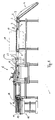
- the plant shown in Figure 1 is shown in side view and has a cross-cut saw 1, which can have several saw blades 2 arranged one behind the other at a distance.
- the goods to be cut are boards 3, which are brought into the horizontal transport plane 5 via a separating device 4.
- the boards 3 are then transported in the transport direction 6 through the system, with eccentrically mounted rollers 7 initially displacing the boards 3 against a lateral stop, not shown here, transversely to the transport direction 6.
- the boards 3 are transported by the accumulation conveyor 11 by means of transport chains 10, which are guided over deflection and drive rollers 8, 9 and are spaced apart from one another. Further details of the accumulation conveyor 11 are shown in FIG. 2.
- the boards 3 arriving one after the other are dammed up into a layer 12 and fed in layers to the cross-cut saw 1 via transport chains 13, 14.
- the transport chain 13, 14 points upwards Toothings which engage on the underside of the boards of the layer 12 in the cutting process.
- the layer 12 After passing through the cross-cut saw 1, the saw blades 2 of which have the direction of rotation indicated by the arrow, the layer 12 reaches the support arms 15, which can be moved longitudinally to the left in the position shown via a stacking device 16. The layer 12 deposited on them is stripped by pulling back the depositing arms 15 in the direction 17 on a pivotable scraper 18, so that the layer 12 reaches the stack 19.
- the stack 19 can be raised beforehand so that there is no distance from the layer 12 when stripping.
- the transport chain 14 of the crosscut saw 1 has drivers 20 arranged at a relatively large distance, each of which engages on the last board 3 of the layer 12 on the back. Since the boards within the layer 12 are not exactly aligned longitudinally and transversely to one another, support rails 21 which can raise the layer 12 from below are provided below the transport plane in the region of the transport chain 14. The further transport of the layer 12 can thus be stopped despite the transport chain 14 running until its driver 20 comes to rest on the last board 3 of the layer 12, the layer 20 being longitudinally aligned using a longitudinally movable ruler 21a and arranged parallel to one another by the carriers 20 . The support rails 21, which are arranged next to one another at a lateral spacing, are then lowered again so that the layer 12 is now transported further on the drivers to the saw blades 2 on the chain 14.
- the devices of the accumulation conveyor 11 can be seen in particular in FIG.
- the accumulation conveyor 11 has a transport chain 10 with smooth plates or with smooth links in order to obtain the smoothest possible transport level 5.
- the boards 3 transported further on the chain 10 in the transport direction 6 reach a lowerable stop 22, on which the boards are dammed up to a layer 12.
- the end of the layer 12 is determined by a layer separator 23 which can be raised to the position shown by means of a lifting cylinder 24.
- the board 3 lying above it is pressed against the underside of a layer guide 25 and clamped in the process.
- the layer guide 25 must assume the position shown with broken line 26.
- the upper position of the layer guide 25, shown with a solid line is used with correspondingly thicker boards or squared timbers.
- the layer guide 25 can be brought to the height adapted to the material to be cut by means of a drive device 27.
- the stop 22, like the layer separator 23, can be displaced vertically by means of a lifting cylinder 28. If the stop 22 is lowered below the transport plane 5, the layer 12 is transported further in the transport direction 6 to the crosscut saw 1.
- the layer separator 23 is fastened in a longitudinally displaceable manner on a rod-shaped longitudinal guide 29, the longitudinal guide 29 being pivotable about a pivot bearing 30 by means of the lifting cylinder 24.
- the layer separator 23 can be fixed at any point on the longitudinal guide 29 by means of a locking device 31.
- a second position of the layer separator 23 for conventional layer widths is shown with broken lines 32, for example.
Abstract
Description
Die Erfindung betrifft eine Ablängvorrichtung für Bretter, Kanthölzer oder dergleichen mit Fördereinrichtungen und einer Ablängsäge, wobei die Fördereinrichtungen über Umlenkrollen geführte, parallel angeordnete Transportketten oder dergleichen besitzen, die das abzulängende Gut zur Ablängsäge transportieren.The invention relates to a cutting device for boards, squared timbers or the like with conveying devices and a cross-cutting saw, the conveying devices having transport chains or the like which are guided over deflection rollers and which transport the material to be cut to the cross-cutting saw.
In derartigen Ablängvorrichtungen können beispielsweise Bretter oder Kanthölzer gleicher Länge mehrfach abgelängt werden. Zu diesem Zweck können die quer zur Transportrichtung liegenden Bretter einer Ablängsäge mit im Abstand angeordneten Sägeblättern zugeführt werden. Der Abstand der Sägeblätter bestimmt somit die Länge der abgelängten Bretter. Bei herkömmlichen Ablängvorrichtungen werden die Bretter zunächst vereinzelt, d.h. daß die Bretter im Abstand hintereinanderliegend mittels Transportketten zur Ablängsäge transportiert werden. Mittels Mitnehmer, die an den Transportketten nach außen abstehen, werden die Bretter durch die Ablängsäge geführt. Anschließend müssen die einzeln abgelängten Bretter wieder zu einer Lage zusammengeführt werden, damit ein lageweises Ablegen der Bretter möglich ist.In such cutting devices, for example, boards or squared timbers of the same length can be cut several times. For this purpose, the boards lying transversely to the transport direction can be fed to a cross-cut saw with saw blades arranged at a distance. The distance between the saw blades thus determines the length of the cut boards. In conventional cross-cutting devices, the boards are first separated, ie the boards are transported one behind the other by means of transport chains to the cross-cut saw. The boards are guided through the cross-cut saw by means of drivers that protrude outwards on the transport chains. The individually cut boards must then be brought together again to form a layer, so that the boards can be laid down layer by layer is.
Der Erfindung liegt die Aufgabe zugrunde, eine Ablängvorrichtung der eingangs genannnten Gattung derart weiterzubilden, daß das abzulängende Gut nicht einzeln, sondern lagenweise abgelängt wird.The invention has for its object to develop a cutting device of the type mentioned in such a way that the material to be cut is not cut to length, but in layers.
Die Lösung dieser Aufgabe wird bei einer Ablängeinrichtung der eingangs genannten Gattung dadurch erhalten, daß in Transportrichtung vor der Ablängsäge ein Stauförderer angeordnet ist, der wenigstens einen absenkbaren Anschlag hat, an dem das abzulängende Gut aufgestaut wird, und daß im Abstand vom Anschlag ein Lagentrenner vorgesehen ist, der eine am Anschlag aufgestaute Lage des abzulängenden Guts am Lagenende von weiterem Gut abtrennt. Auf diese Weise ist es möglich, die zwischen Anschlag und Lagentrenner aufgestaute Lage in ihrer Gesamtheit zur Ablängsäge weiterzutransportieren, wo die Lage dann auf das eingestellte Maß abgelängt wird. Die abgelängte Lage läßt sich dann in einem Arbeitsgang auf Ablegearme transportieren, die die Lage dann auf einem Stapel ablegen können. Dadurch, daß die dem Stauförderer nachgeordnete Ablängsäge als Fördereinrichtung gezahnte Transportketten hat, ist sichergestellt, daß jeweils das mit dem Sägeblatt in Berührung befindliche Brett durch die an der Schnittkante vom Sägeblatt ausgeübte vertikale Kraftkomponente in die Verzahnung etwas eingedrückt wird und dadurch sicher von den nebeneinander angeordneten Transportketten durch die Ablängsäge transportiert werden kann. Hier kann auch eine Oberdruckrolle oder dergleichen zusätzlich zu diesem Zweck vorgesehen sein.The solution to this problem is obtained with a cutting device of the type mentioned in the introduction that a accumulation conveyor is arranged in the transport direction in front of the cutting saw, which has at least one lowerable stop on which the material to be cut is pent-up, and that a layer separator is provided at a distance from the stop is that separates a pent-up position of the goods to be cut to length at the end of the layer from other goods. In this way it is possible to transport the entire position of the pent-up position between the stop and the layer separator to the cross-cut saw, where the position is then cut to the set dimension. The cut-to-length layer can then be transported in one operation on depositing arms, which can then deposit the layer on a stack. The fact that the cross-cutting saw arranged downstream of the accumulation conveyor has toothed transport chains ensures that the board in contact with the saw blade is pressed somewhat into the toothing by the vertical force component exerted on the cutting edge by the saw blade and thereby safely arranged by the side by side Transport chains can be transported through the crosscut saw. An upper pressure roller or the like can also be provided here for this purpose.
Der Abstand zwischen Anschlag und Lagentrenner ist vorzugsweise einstellbar ausgebildet, damit die Länge der jeweils abzulängenden Lage einstellbar ist.The distance between the stop and the layer separator is preferably adjustable so that the length of the layer to be cut to length can be adjusted.
Der Anschlag und der Lagentrenner sind jeweils mittels Antriebs vertikal verschiebbar, damit durch Absenken des Anschlags die aufgestaute Lage zur Ablängsäge weitertransportiert werden kann. Der Lagentrenner wird angehoben, um das Ende der Lage beispielsweise durch Festklemmen des nächsten Brettes zu bestimmen. Die Lagenbreite läßt sich somit sehr einfach festlegen. Besonders vorteilhaft ist es, den Lagentrenner auf einer Längsführung zu befestigen, die an ihrem, dem Anschlag abgewandten Ende schwenkbar gelagert ist. Die Längsführung kann auch parallelverschiebbar angeordnet sein. Die Längsführung wird dabei vorzugsweise mittels eines Zylinders in der Höhe verschwenkt. Die Einstellung des Lagentrenners ist entlang einer stabförmigen Längsführung sehr einfach, wobei auch der Antrieb in Form eines ortsfest angeordneten Zylinders sehr einfach ist.The stop and the layer separator can each be moved vertically by means of a drive, so that the pent-up position can be transported to the cross-cut saw by lowering the stop. The layer separator is raised in order to determine the end of the layer, for example by clamping the next board. The layer width can thus be determined very easily. It is particularly advantageous to fasten the layer separator on a longitudinal guide which is pivotably mounted at its end facing away from the stop. The longitudinal guide can also be arranged to be displaceable in parallel. The longitudinal guide is preferably pivoted in height by means of a cylinder. The adjustment of the position separator is very simple along a rod-shaped longitudinal guide, and the drive in the form of a stationary cylinder is also very simple.
Im Bereich des Stauförderers ist oberhalb der Transportebene vorzugsweise eine Lagenführung angeordnet, die gleichzeitig als Gegenhalter für die Lagentrenner dient. Der Lagentrenner kann somit ein über ihm befindliches Brett oder dergleichen gegen die Lagenführung pressen und somit in dieser Position festklemmen. Die vor dem festgeklemmten Brett befindlichen Bretter können nun vom Kettenförderer zur Ablängsäge gemeinsam weitertransportiert werden.In the area of the accumulation conveyor, a layer guide is preferably arranged above the transport plane, which also serves as a counter-holder for the layer separator. The layer separator can thus press a board or the like located above it against the layer guide and thus clamp it in this position. The boards in front of the clamped board can now be transported together from the chain conveyor to the cross-cut saw.
Im Bereich des Stauförderers sind die Transportketten vorzugsweise glatt ausgebildet, d.h. daß die Transportketten vorzugsweise gerade Laschen bzw. gerade Kettenglieder haben. Durch die dadurch erhaltene glatte Transportfläche können die Bretter problemlos an einem Anschlag hintereinander aufgestaut werden, wobei die glatten Transportketten unterhalb der aufgestauten Bretter hindurchrutschen können.In the area of the accumulation conveyor, the transport chains are preferably smooth, ie the transport chains preferably have straight links or straight chain links. As a result of the smooth transport surface thus obtained, the boards can easily be stowed one behind the other at a stop, the smooth transport chains being able to slide underneath the stowed boards.
Die Transportketten im Bereich der Mehrfachablängsäge besitzen Mitnehmer, die in einem größeren Abstand hintereinander angeordnet sind, als die maximale Breite einer abzulängenden Lage. Die Mitnehmer können somit jeweils am letzten Brett der abgetrennten Lage angreifen, um die Lage problemlos durch die Ablängsäge zu befördern.The transport chains in the area of the multiple crosscut saw have drivers which are arranged one behind the other at a greater distance than the maximum width of a layer to be cut to length. The drivers can thus attack the last board of the separated layer in order to easily transport the layer through the cross-cut saw.
Vor den Sägeblättern sind unterhalb der Förderebene anhebbare Auflageschienen zweckmäßig, die unmittelbar vor dem Ablängvorgang geringfügig über die Transportebene angehoben sind. Die zur Ablängsäge transportierte Lage wird dadurch solange nicht weitertransportiert, bis der Mitnehmer der Transportkette am letzten Brett der Lage angreift und diese parallel zueinander ausrichtet. Gleichzeitig wird stirnseitig ein Lineal gegen die Lage gefahren, das die Teile längs zueinander und auf die Anschlagsäge ausrichtet. Die Auflageschienen werden dann wieder abgesenkt, damit die Lage auf den gezahnten Transportketten zu liegen kommt.In front of the saw blades, support rails that can be raised below the conveying level are expedient, which are raised slightly above the transport level immediately before the cutting process. The layer transported to the crosscut saw will not be transported further until the driver of the transport chain engages the last board of the layer and aligns it parallel to one another. At the same time, a ruler is moved against the face at the end, which aligns the parts lengthways to each other and to the fence saw. The support rails are then lowered again so that the position comes to rest on the toothed transport chains.
Eine Weiterbildung der Erfindung sieht vor, daß hinter der Ablängsäge eine Stapeleinrichtung angeordnet ist, die die jeweils abgelängte Lage auf Ablegearme schiebt, die an Abstreifern die auf ihnen abgelegte Lage auf einen Stapel abstreifen. Durch diese Maßnahme kann jeweils eine abgelängte Lage komplett aufgestapelt werden.A further development of the invention provides that a stacking device is arranged behind the cross-cut saw, which pushes the respective cut-to-length position onto depositing arms, which scrape the position deposited on them onto a stack on scrapers. With this measure, a cut-to-length layer can be stacked completely.
Gemäß einer besonders vorteilhaften Weiterbildung der Erfindung ist vorgesehen, daß vor dem Lagentrenner exzentrisch gelagerte Walzen als Querförderer angeordnet sind, deren Achsen in Transportrichtung der Förderketten liegen und die Rotation mit ihrer Mantelfläche zyklisch an der Transportebene oben heraustreten. Entsprechend der Drehrichtung der exzentrisch gelagerten Walzen läßt sich somit das abzulängende Gut seitlich gegen einen Anschlag transportieren, wodurch eine einheitliche Ausrichtung sämtlicher abzulängenden Bretter oder dergleichen erreicht wird.According to a particularly advantageous development of the invention, it is provided that eccentrically mounted rollers are arranged as cross conveyors in front of the layer separator, the axes of which lie in the transport direction of the conveyor chains and the surface of the rotation emerge cyclically at the transport level at the top. Depending on the direction of rotation of the eccentrically mounted rollers, the material to be cut can thus be turned sideways Transport a stop, whereby a uniform alignment of all boards to be cut or the like is achieved.
Die Erfindung wird nachfolgend anhand der Zeichnung näher erläutert.The invention is explained below with reference to the drawing.
Es zeigen:
- Figur 1 den Aufbau einer erfindungsgemäßen Ablängvorrichtung mit Stapeleinrichtung und
- Figur 2 einen Ausschnitt aus der in Figur 1 dargestellten Ablängvorrichtung im Bereich des Stauförderers.
- Figure 1 shows the structure of a cutting device according to the invention with a stacking device and
- Figure 2 shows a section of the cutting device shown in Figure 1 in the area of the accumulation conveyor.
Die in Figur 1 dargestellte Anlage ist in der Seitenansicht dargestellt und besitzt eine Ablängsäge 1, die mehrere hintereinander im Abstand angeordnete Sägeblätter 2 besitzen kann. Das abzulängende Gut sind im dargestellten Beispiel Bretter 3, die über eine Vereinzelungseinrichtung 4 in die waagrechte Transportebene 5 gebracht werden. Die Bretter 3 werden dann in Transportrichtung 6 durch die Anlage transportiert, wobei zunächst exzentrisch gelagerte Walzen 7 die Bretter 3 gegen einen hier nicht dargestellten seitlichen Anschlag quer zur Transportrichtung 6 verschieben.The plant shown in Figure 1 is shown in side view and has a cross-cut saw 1, which can have several saw blades 2 arranged one behind the other at a distance. In the example shown, the goods to be cut are
Mittels über Umlenk- und Antriebrollen 8, 9 geführte Transportketten 10, die im Abstand nebeneinander angeordnet sind, werden die Bretter 3 durch den Stauförderer 11 transportiert. Weitere Einzelheiten des Stauförderers 11 sind in Figur 2 dargestellt.The
Im Stauförderer 11 werden die nacheinander ankommenden Bretter 3 zu einer Lage 12 aufgestaut und lagenweise der Ablängsäge 1 über Transportketten 13, 14 zugeführt. Die Transportkette 13, 14 weist nach oben gerichtete Verzahnungen auf, die an der Unterseite der Bretter der Lage 12 in diese beim Ablängvorgang eingreifen.In the
Nach Durchlaufen der Ablängsäge 1, deren Sägeblätter 2 die mit Pfeil angegebene Drehrichtung haben, gelangt die Lage 12 auf Ablegearme 15, die in die dargestellte Stellung nach links über eine Stapeleinrichtung 16 längsverschiebbar sind. Die auf ihnen abgelegte Lage 12 wird durch Zurückziehen der Ablegearme 15 in Richtung 17 an einem verschwenkbaren Abstreifer 18 abgestreift, so daß die Lage 12 auf den Stapel 19 gelangt. Der Stapel 19 kann zuvor angehoben werden, damit zur Lage 12 kein Abstand beim Abstreifen besteht.After passing through the cross-cut saw 1, the saw blades 2 of which have the direction of rotation indicated by the arrow, the
Die Transportkette 14 der Ablängsäge 1 besitzt in verhältnismäßig großem Abstand angeordnete Mitnehmer 20, die jeweils am letzten Brett 3 der Lage 12 rückseitig angreifen. Da die Bretter innerhalb der Lage 12 längs und quer noch nicht genau zueinander ausgerichtet sind, sind unterhalb der Transportebene im Bereich der Transportkette 14 anhebbare Auflageschienen 21 vorgesehen, die die Lage 12 von unten anheben können. Der Weitertransport der Lage 12 kann dadurch solange trotz laufender Transportkette 14 gestoppt werden, bis deren Mitnehmer 20 am letzten Brett 3 der Lage 12 zur Anlage kommt wobei die Lage 20 über ein längsverfahrbares Lineal 21 a längsausgerichtet und durch die Mitnehmer 20 parallel nebeneinander liegend angeordnet wird. Die Auflageschienen 21, die im seitlichen Abstand nebeneinander angeordnet sind, werden dann wieder nach unten abgesenkt, so daß die Lage 12 nun an den Mitnehmern zu den Sägeblättern 2 auf der Kette 14 weitertransportiert wird.The
In Figur 2 sind insbesondere die Einrichtungen des Stauförderers 11 ersichtlich. Der Stauförderer 11 hat eine Transportkette 10 mit glatten Laschen bzw. mit glatten Gliedern, um eine möglichst glatte Transportebene 5 zu erhalten. Die in Transportrichtung 6 auf der Kette 10 weitertransportierten Bretter 3 gelangen an einen absenkbaren Anschlag 22, an dem die Bretter zu einer Lage 12 aufgestaut werden. Das Ende der Lage 12 wird durch einen Lagentrenner 23 bestimmt, der mittels eines Hubzylinders 24 in die dargestellte Position angehoben werden kann. Dabei wird das über ihm liegende Brett 3 gegen die Unterseite einer Lagenführung 25 gedrückt und dabei festgeklemmt. Die Lagenführung 25 muß dabei die mit unterbrochener Linie 26 dargestellte Position einnehmen. Die oberere mit durchgezogener Linie dargestellte Position der Lagenführung 25 wird bei entsprechend dickeren Brettern oder Kanthölzern verwendet. Mittels einer Antriebeinrichtung 27 kann die Lagenführung 25 in die dem abzulängenden Gut angepaßte Höhe gebracht werden.The devices of the
Der Anschlag 22 ist ebenso wie der Lagentrenner 23 mittels einem Hubzylinders 28 vertikal verschiebbar. Wird der Anschlag 22 unter die Transportebene 5 gesenkt, so wird die Lage 12 in Transportrichtung 6 zur Ablängsäge 1 weitertransportiert.The
Der Lagentrenner 23 ist auf einer stabförmigen Längsführung 29 längsverschiebbar befestigt, wobei die Längsführung 29 um ein Schwenklager 30 mittels des Hubzylinders 24 verschwenkbar ist. Der Lagentrenner 23 kann mittels einer Feststelleinrichtung 31 an jeder beliebigen Stelle der Längsführung 29 festgestellt werden. Eine zweite Position des Lagentrenners 23 für übliche Lagenbreiten ist mit unterbrochenen Linien 32 beispielsweise dargestellt.The
Claims (12)
- Device for cutting boards, squared timber or the like to length, with conveyor devices and a cross-cut saw, the conveyor devices having parallel conveyor chains or the like, led over deflecting rollers, and conveying to the cross-cut saw the material which is to be cut to length, and with an accumulating conveyor which is arranged in front of the cross-cut saw in the conveying direction and has at least one stop member which can be lowered and against which the material to be cut to length is accumulated, characterised in that at a distance from the stop member (22) a layer separator (23) is provided which separates a layer (12) of the material to be cut to length that is accumulated against the stop member (22) from the further material, at the end of the layer, and that the cross-cut saw (1) arranged downstream of the accumulating conveyor (11) has toothed conveyor chains (14) as the conveyor device.
- Length-cutting device according to Claim 1, characterised in that the distance between the stop member (22) and the layer separator (23) is adjustable.
- Length-cutting device according to either of Claims 1 and 2, characterised in that the stop member (22) and the layer separator (23) are each vertically displaceable by means of a drive (28; 24).
- Length-cutting device according to one of the preceding Claims, characterised in that the layer separator (23) is fastened on a longitudinal guide (29) which at its end remote from the stop member (22) is mounted so as to be pivotable or to be displaceable parallel to itself.
- Length-cutting device according to Claim 4, characterised in that the longitudinal guide (29) is pivotable by means of a lifting cylinder (24).
- Length-cutting device according to one of the preceding Claims, characterised in that the layer separator (23) in its upper position firmly clamps the board (3) or the like which is located above it.
- Length-cutting device according to Claim 6, characterised in that the accumulating conveyor (11) has a layer guide (25) which is arranged over its conveyor path and which serves as a guide for the layer (12) and as a counter-clamp for the layer separator (23).
- Length-cutting device according to one of the preceding Claims, characterised in that the conveyor chains (10), in the region of the accumulating conveyor (11), form a generally smooth conveying plane (5) through the use of straight chain links.
- Length-cutting device according to Claim 1, characterised in that the toothed conveyor chains (14) have carrier members (20) which are arranged at a distance one behind the other which is greater than the maximum width of a layer (12) to be cut to length.
- Length-cutting device according to Claim 9, characterised in that the conveyor device of the cross-cut saw (1) has support rails (21) which are arranged in front of the saw blades (2) and can be lifted up.
- Length-cutting device according to one of the preceding Claims, characterised in that behind the cross-cut saw (1) there is arranged a stacking device (16) which pushes each cut-to-length layer (12) onto depositing arms (15) which against stripper members (18) strip off onto a stack (19) the layer (12) deposited on them.
- Length-cutting device according to one of the preceding Claims, characterised in that in front of the layer separator (23) there are arranged eccentrically mounted rollers (7) as transverse conveyors, the axes of which lie in the conveying direction of the conveyor chains and which, on rotation, emerge cyclically at the top with their outer surface on the conveying plane (5).
Priority Applications (1)
| Application Number | Priority Date | Filing Date | Title |
|---|---|---|---|
| AT90108021T ATE96721T1 (en) | 1989-04-29 | 1990-04-27 | LENGTHING DEVICE. |
Applications Claiming Priority (2)
| Application Number | Priority Date | Filing Date | Title |
|---|---|---|---|
| DE3914320A DE3914320C2 (en) | 1989-04-29 | 1989-04-29 | Cutting device |
| DE3914320 | 1989-04-29 |
Publications (3)
| Publication Number | Publication Date |
|---|---|
| EP0396032A2 EP0396032A2 (en) | 1990-11-07 |
| EP0396032A3 EP0396032A3 (en) | 1991-07-31 |
| EP0396032B1 true EP0396032B1 (en) | 1993-11-03 |
Family
ID=6379826
Family Applications (1)
| Application Number | Title | Priority Date | Filing Date |
|---|---|---|---|
| EP90108021A Expired - Lifetime EP0396032B1 (en) | 1989-04-29 | 1990-04-27 | Device for cross-cutting workpieces to desired lengths |
Country Status (3)
| Country | Link |
|---|---|
| EP (1) | EP0396032B1 (en) |
| AT (1) | ATE96721T1 (en) |
| DE (1) | DE3914320C2 (en) |
Families Citing this family (1)
| Publication number | Priority date | Publication date | Assignee | Title |
|---|---|---|---|---|
| CN108000632A (en) * | 2017-11-18 | 2018-05-08 | 深圳市安东尼奥家具有限公司 | Sizing saw machine |
Family Cites Families (24)
| Publication number | Priority date | Publication date | Assignee | Title |
|---|---|---|---|---|
| US3127029A (en) * | 1964-03-31 | Device for separating individual groups of flat articles | ||
| US2679919A (en) * | 1952-03-15 | 1954-06-01 | Koning Edwin W De | Lumber transfer mechanism |
| CH345147A (en) * | 1955-02-15 | 1960-03-15 | Bauwerk Bodenbelagsind Ag | Method and device for the crosswise assembly of small parquet strips to form parquet panels |
| US2878919A (en) * | 1955-02-16 | 1959-03-24 | R A Jones And Company Inc | Article metering apparatus |
| US2911081A (en) * | 1956-10-10 | 1959-11-03 | Dixon Automatic Tool | Feed control mechanism |
| US3197064A (en) * | 1963-03-08 | 1965-07-27 | Lamb Co F Jos | Adjustable escapement mechanism for delivering workpieces |
| US3486602A (en) * | 1966-05-26 | 1969-12-30 | Stetson Ross Machine Co Inc | Transfer system overdrop with lumber retarder |
| DE1998960U (en) * | 1966-09-30 | 1968-12-19 | Siemens Ag | HOLDING AND DOSING DEVICE FOR CONVEYORS IN A CONVEYOR DEVICE |
| US3366222A (en) * | 1966-10-27 | 1968-01-30 | Lodge & Shipley Co | Feed conveyor gate |
| DE6917355U (en) * | 1969-04-29 | 1969-08-07 | Wilhelm Ulrich Maisch | DEVICE FOR CUTTING HEMED SLATS |
| DE2103733A1 (en) * | 1971-01-27 | 1972-08-10 | Hurth Masch Zahnrad Carl | Device for destacking and marking workpieces |
| CH560151A5 (en) * | 1972-02-01 | 1975-03-27 | Balz Rudolf | |
| US3812951A (en) * | 1972-05-16 | 1974-05-28 | Weyerhaeuser Co | Log handling apparatus |
| US4029198A (en) * | 1973-07-05 | 1977-06-14 | Lingl Corporation | Method and apparatus for forming groups of bricks |
| SE7400437L (en) * | 1974-01-14 | 1975-07-15 | Gunnar Thure Eliassen | TRANSPORT FACILITY |
| DE2540985C3 (en) * | 1975-09-13 | 1980-09-11 | Enzinger-Union-Werke Ag, 6800 Mannheim | Conveyor rocker |
| DE2704634A1 (en) * | 1977-02-04 | 1978-08-10 | Ernst Kallfass Maschbau | Circular saw with top pressure device - has chain wheels and supporting guide rail for passively driven sprocket chain |
| DE2722325A1 (en) * | 1977-05-17 | 1978-11-30 | Weinig Michael Kg | Plank stacking machine loading mechanism - has movable retainer unit above loading conveyor before removable stop |
| DE2925218B1 (en) * | 1979-06-22 | 1981-01-08 | Lingl Anlagenbau | Device for grouping rows of moldings |
| DE3024993C2 (en) * | 1980-07-02 | 1984-06-07 | Karl Haist KG, 8000 München | Device for the individual feeding of boards to a treatment facility |
| SE424282B (en) * | 1980-12-23 | 1982-07-12 | Hammars Mekaniska Verkstad Ab | PROCEDURE FOR ADJUSTING THE WORK PIECE WITH A DEVICE FOR CARRYING OUT THE PROCEDURE |
| DE3300351C2 (en) * | 1983-01-07 | 1985-02-28 | Anthon GmbH & Co Maschinenfabrik, 2390 Flensburg | Device for dividing panels, in particular chipboard |
| FR2550120B1 (en) * | 1983-08-04 | 1985-11-22 | Nacelle | DEVICE FOR CUTTING ELONGATED ELEMENTS WITH RECTANGULAR SECTION INTO SECTION OF A PREDETERMINED LENGTH |
| DE3540791A1 (en) * | 1985-11-16 | 1987-05-21 | Keller Gmbh & Co Kg | Apparatus for conveying carrying laths beneath green bricks advanced on conveyor belts |
-
1989
- 1989-04-29 DE DE3914320A patent/DE3914320C2/en not_active Expired - Fee Related
-
1990
- 1990-04-27 EP EP90108021A patent/EP0396032B1/en not_active Expired - Lifetime
- 1990-04-27 AT AT90108021T patent/ATE96721T1/en not_active IP Right Cessation
Also Published As
| Publication number | Publication date |
|---|---|
| EP0396032A3 (en) | 1991-07-31 |
| DE3914320A1 (en) | 1990-10-31 |
| DE3914320C2 (en) | 1994-04-14 |
| EP0396032A2 (en) | 1990-11-07 |
| ATE96721T1 (en) | 1993-11-15 |
Similar Documents
| Publication | Publication Date | Title |
|---|---|---|
| DE2714973C2 (en) | Device for advancing raw boards to an edging saw | |
| DE3632895A1 (en) | DEVICE AND METHOD FOR REMOVING PROTECTIVE FILMS | |
| WO1991000168A1 (en) | Device for cutting stacked sheet material | |
| EP2127828B1 (en) | Device for separating a processable stack from an initial stack by cutting | |
| EP0504442A1 (en) | Device for feeding workpieces to a production machine | |
| EP1072546B1 (en) | Conveyer for collating and processing printed sheets | |
| EP0831045B1 (en) | Method and device for opening flexible and flat products | |
| EP0396032B1 (en) | Device for cross-cutting workpieces to desired lengths | |
| DE2805870C2 (en) | Device for cross-cutting rubber sheets | |
| DE10242353B4 (en) | Cross pusher | |
| DE2501012A1 (en) | Timber cutting and stacking - transports partial stacks of timber transverse to their long direction and pushes separate stacks onto platform(s) | |
| EP2143671A1 (en) | Packet assembling device | |
| AT397058B (en) | TENSIONING AND FEEDING DEVICE FOR TREATING TRUNKS | |
| DE3402497C2 (en) | Device for cutting wood and then processing the wood sections on the side edges | |
| DE1549744B2 (en) | Device for the individual feeding of stacked recording media | |
| DE2007331C3 (en) | Device for staggered depositing of boards on a conveyor track | |
| EP2436623B1 (en) | Method and device for removing a row of stacks | |
| DE3342064C2 (en) | ||
| EP2316767B1 (en) | Device and method for manufacturing printed product stacks | |
| DE19948704C1 (en) | Unit for combined transporting and turning a horizontal stack of paper sheets, comprises a displaceable and rotatable disk and a fixed holding-down plate whose surface has a lower coefficient of friction | |
| DE3316284A1 (en) | Device for maintaining a specific position of a flattened piece of wood during transport between work stations | |
| DE4105371C2 (en) | Device for cutting a strand of foam | |
| DE2546799C2 (en) | Feeding device | |
| DE2107944C (en) | Device for feeding and stacking loose sheets of paper | |
| DE10037658C2 (en) | Device for sorting boards from a wooden carpet |
Legal Events
| Date | Code | Title | Description |
|---|---|---|---|
| PUAI | Public reference made under article 153(3) epc to a published international application that has entered the european phase |
Free format text: ORIGINAL CODE: 0009012 |
|
| AK | Designated contracting states |
Kind code of ref document: A2 Designated state(s): AT CH FR LI SE |
|
| PUAL | Search report despatched |
Free format text: ORIGINAL CODE: 0009013 |
|
| AK | Designated contracting states |
Kind code of ref document: A3 Designated state(s): AT CH FR LI SE |
|
| RHK1 | Main classification (correction) |
Ipc: B27B 31/00 |
|
| 17P | Request for examination filed |
Effective date: 19910703 |
|
| 17Q | First examination report despatched |
Effective date: 19930414 |
|
| GRAA | (expected) grant |
Free format text: ORIGINAL CODE: 0009210 |
|
| AK | Designated contracting states |
Kind code of ref document: B1 Designated state(s): AT CH FR LI SE |
|
| REF | Corresponds to: |
Ref document number: 96721 Country of ref document: AT Date of ref document: 19931115 Kind code of ref document: T |
|
| ET | Fr: translation filed | ||
| PLBE | No opposition filed within time limit |
Free format text: ORIGINAL CODE: 0009261 |
|
| STAA | Information on the status of an ep patent application or granted ep patent |
Free format text: STATUS: NO OPPOSITION FILED WITHIN TIME LIMIT |
|
| 26N | No opposition filed | ||
| EAL | Se: european patent in force in sweden |
Ref document number: 90108021.8 |
|
| PGFP | Annual fee paid to national office [announced via postgrant information from national office to epo] |
Ref country code: CH Payment date: 20020411 Year of fee payment: 13 |
|
| PGFP | Annual fee paid to national office [announced via postgrant information from national office to epo] |
Ref country code: AT Payment date: 20020422 Year of fee payment: 13 |
|
| PGFP | Annual fee paid to national office [announced via postgrant information from national office to epo] |
Ref country code: SE Payment date: 20020425 Year of fee payment: 13 |
|
| PGFP | Annual fee paid to national office [announced via postgrant information from national office to epo] |
Ref country code: FR Payment date: 20020429 Year of fee payment: 13 |
|
| PG25 | Lapsed in a contracting state [announced via postgrant information from national office to epo] |
Ref country code: AT Free format text: LAPSE BECAUSE OF NON-PAYMENT OF DUE FEES Effective date: 20030427 |
|
| PG25 | Lapsed in a contracting state [announced via postgrant information from national office to epo] |
Ref country code: SE Free format text: LAPSE BECAUSE OF NON-PAYMENT OF DUE FEES Effective date: 20030428 |
|
| PG25 | Lapsed in a contracting state [announced via postgrant information from national office to epo] |
Ref country code: LI Free format text: LAPSE BECAUSE OF NON-PAYMENT OF DUE FEES Effective date: 20030430 Ref country code: CH Free format text: LAPSE BECAUSE OF NON-PAYMENT OF DUE FEES Effective date: 20030430 |
|
| EUG | Se: european patent has lapsed | ||
| REG | Reference to a national code |
Ref country code: CH Ref legal event code: PL |
|
| PG25 | Lapsed in a contracting state [announced via postgrant information from national office to epo] |
Ref country code: FR Free format text: LAPSE BECAUSE OF NON-PAYMENT OF DUE FEES Effective date: 20031231 |
|
| REG | Reference to a national code |
Ref country code: FR Ref legal event code: ST |