EP0395602A2 - Heisses Thermoelement zur Niveaumessung und zur Phasenbestimmung bei hohen Temperaturen und Drücken - Google Patents
Heisses Thermoelement zur Niveaumessung und zur Phasenbestimmung bei hohen Temperaturen und Drücken Download PDFInfo
- Publication number
- EP0395602A2 EP0395602A2 EP90830182A EP90830182A EP0395602A2 EP 0395602 A2 EP0395602 A2 EP 0395602A2 EP 90830182 A EP90830182 A EP 90830182A EP 90830182 A EP90830182 A EP 90830182A EP 0395602 A2 EP0395602 A2 EP 0395602A2
- Authority
- EP
- European Patent Office
- Prior art keywords
- sheath
- sensor
- thermocouple
- fluid
- temperature
- Prior art date
- Legal status (The legal status is an assumption and is not a legal conclusion. Google has not performed a legal analysis and makes no representation as to the accuracy of the status listed.)
- Granted
Links
Images


Classifications
-
- G—PHYSICS
- G01—MEASURING; TESTING
- G01F—MEASURING VOLUME, VOLUME FLOW, MASS FLOW OR LIQUID LEVEL; METERING BY VOLUME
- G01F23/00—Indicating or measuring liquid level or level of fluent solid material, e.g. indicating in terms of volume or indicating by means of an alarm
- G01F23/22—Indicating or measuring liquid level or level of fluent solid material, e.g. indicating in terms of volume or indicating by means of an alarm by measuring physical variables, other than linear dimensions, pressure or weight, dependent on the level to be measured, e.g. by difference of heat transfer of steam or water
Definitions
- the object of the present finding consists in a phase-indicating, level- and vacuum fractions-measuring device for employment at high temperatures and pressures , which comprises in combination at least a hot-thermocouple sensor and a supply electronic circuit which is capable of detecting the (liquid or gas) phase present at the sensitive point of the sensor itself. Owing to its characteristics, said device lends itself to the measurement of levels under static and dynamic conditions of biphase mixtures (through a plurality of sensors) as well as to measurements for identifying the structure of biphase outflows.
- biphase-level and vacuum-fraction measurements are performed at the present time by employing point sensors for identifying the phase.
- a partial solution to the problem is offered at present by the employment of a fully sheathed sensor which, as a consequence, is much more resistant to the action of temperature and pressure, in which sensor the phase distinction occurs on the basis of the heat amount removed by the process fluid through a sheath which is electrically heated by a constant supply up to a temperature higher than that of the fluid itself.
- This invention obviates all drawbacks pointed out above, and it also reduces the sizes of the sensitive portion (i.e., the sensor) which thus turns out to be miniaturized.
- the measuring device comprises, in combination with the sensor and with one another, a thermocouple which serves the aim of performing the measurement of the fluid temperature, and a variable supply unit serving the purpose of realizing an electric supply to the heater, said supply being "negatively fed-back" in relation to the phase changes at the sensor and to the temperature of the process fluid.
- the supply system tends to keep the temperature difference between the sensor and the fluid at a constant value ( ⁇ T of reference).
- the system reacts in order to keep the ⁇ T value constant by increasing the current through the heater in the first instance (gas-liquid change), and by decreasing said current in the other instance (liquid-gas change) .
- a further innovation consists in that the supply current intensity is taken and measured, instead of measuring the signal of the hot thermocouple.
- the apparatus is characterized by: a sensor which is made up of a sheath inside which an electric heater is arranged which is coaxially wound about a micro-thermocouple (TC sensor); another outer thermocouple (fluid TC) characterized by a slow response that serves the purpose of performing the measurement of the fluid temperature; a negative feedback supply unit which supplies a current of such a value as to keep a constant temperature difference ⁇ T between the fluid (fluid TC) and the TC sensor.
- TC sensor micro-thermocouple
- fluid TC another outer thermocouple characterized by a slow response that serves the purpose of performing the measurement of the fluid temperature
- a negative feedback supply unit which supplies a current of such a value as to keep a constant temperature difference ⁇ T between the fluid (fluid TC) and the TC sensor.
- the fluid TC is series connected to the inner TC of the sensor so that the signal detected by said supply unit is proportional to the temperature difference between the sensor and the fluid.
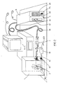
- the reference numeral 1 points out a reservoir (a container, a pipe and so on), while number 2 points out a probe, 3 points out a connector that connects said probe to the board of a control and measurement electronic unit 5.
- the reference numeral 6 points out a signal meter and/or processor, while 7 points out the supply.
- 1B is an air-distributing device connected to an air bubbling device 1A.
- the bubble distributing device 1B for distributing air from the bubbler 1A is arranged inside the reservoir 1 for giving rise to a situation similar to that encountered for instance in a bi-phase thermofluidodynamic circuit, which situation can be detected through the probe 2 which also is arranged inside said reservoir 1.
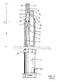
- the probe 2 is made up of an outer steel sheath 10, whose inner portion (Fig. 3) is filled with Al2O3 powder in which three tubular sheaths 12, 13 and 14 are embedded, the two first ones being made up of steel while the third is made up of sintered Al2O3.
- Both sheaths 12 and 13 are filled with a charge 15 of MgO: the first sheath bears two filaments immersed in the MgO charge which form a Cr/Al thermocouple 18 (of type K) which is capable of measuring: levels, vacuum fractions, liquid phases, gas phases, dynamic phases (mono-bi-tri-phase fluids); static and/or dynamic levels that can be observed in the environment in which the measurement is performed, and in the present instance in the reservoir 1 of Figures 1 and 2.
- a Cr/Al thermocouple 18 of type K
- thermocouple 18 serves the purpose of detecting the temperature inside said reservoir 1.
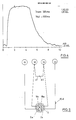
- said sheath 12 is purposely realized so as to have a diameter less than that of the sheath 13 (in the case illustrated herein, about 1/6) in order to obtain a shorter response time as is clearly illustrated in the plots of Fig. 4.
- Said sheath 12 is embedded in the alumina powder of the sheath 10 down to the "cold" portion that extends to the outside starting from a ruby 20 that operates as an insulating and centring component for said sheath 12.
- the sheath 12, in addition to being inserted on said ruby 20, is also inserted into another nickel sheath 21 which is separated and insulated from the sheath 10 through the sintered alumina insulators 22 having the shape of a disc bearing a whole at the centre portion of diameter equal to the outer diameter of the sheath 12.
- a weld 17 (TIG) that forms a single joint between the two sheaths is present above the thermocouple 18 between the nickel sheath 21 and the sheath 12.
- a step is obtained in the inner side of the upper edge of the sheath 10, which step causes the thickness to decrease by an amount equal to the outer diameter of a small hollow cylinder or sleeve 23 whose inner diameter allows the two sheaths 13 and 21 to pass.
- a vacuum brazing is carried out over the whole surface of the sheath 10 and through capillarity till forming a perfectly tight-seal single block once said small cylinder 23 is put inside the sheath 10, in order to ensure a sealed unit.
- the sheaths 12 and 21, while the measurements are performed, are heated up to a previously established temperature (by the Joule effect on the sheath 12) by means of an Ag conducting spiral 16 which is embedded in the alumina powder 11 contained in the sheath 14 down to its upper end, and which is wound around the sheath 12 in the cold zone.
- the electric circuit is closed through the welded part 17 (tungsten welding under inert gas) on the sheath 21.
- the air bubbler 1 B at the base portion of the reservoir 1 is connected to the outer air-distributing device 1A by means of a pipe 1C and a connection 1D arranged on a wall of said reservoir 1.
- the sheath 10 crosses the wall of the reservoir 1 by means of a suitable tight-seal connection 26 and goes to the outside by inserting into a connector 3.
- the connections of the probe 2 with said connector 3 are put into evidence in Fig. 5: the Cr conductors e1 and e2 of the thermocouples 18 and 19 are welded to one another while the Al conductors of the same thermocouples 18 and 19 are welded respectively at the contacts b and c of the connector itself.
- the Ag conductor 16 referred to when illustrating Fig. 3, is welded on the contact a of the same connector 3 while another Ag conductor 10d is welded on the contact d, said conductor being welded at the opposite end with respect to said sheath 10 for closing the circuit with the conductor 16, as illustrated in the detailed part shown in Fig. 3.
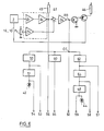
- the 3A cable of the connector 3 is connected at the connection terminals of the electronic unit circuit illustrated in Fig. 7.
- the block I points out the amplification of the input signals coming from the conductors 18A and 18C, which signals, processed in a suitable way, give a difference signal between said two conductors.
- the block II controls the heater current so as to ensure the keeping of the ⁇ T value set forth on the control board which makes up the block 4.
- the block III performs the function of processing in various ways the output of the signal supplying different signals for the different measuring requirements to the output terminals.
- the block IV supplies all circuits of the apparatus consisting of the electronic unit-board-probe.
- the disclosure of the operation of the whole apparatus can be carried out in a parallel way with the detailed examination of the circuit and of the functions that its components perform during the realization of a measurement, for instance in a bi-phase fluidodynamic environment, of the vacuum fraction as an alternative to the identification of the flow-pattern type and/or to the measurement of liquid film thicknesses.
- the operation is carried out by filling the reservoir 1 with a suitable fluid after inserting the probe 2 inside the reservoir itself, the contacts between the probe 2 and the electronic unit 5 are set forth by means of the connector 3 and its cable 3A. A suitable interface (for data acquisition and processing) is connected, and then the supply is provided to the whole system.
- the bubble generating device 1B is put into action and the potentiometer P4 arranged on the board 4 is adjusted, said potentiometer setting forth the power required for heating the sensitive point, which is also called “hot zone” and pointed out by the letter A in Fig. 3, of the probe 2, till reaching a temperature value which is set forth previously by the operator and which corresponds to a previously fixed temperature difference between said sensitive point A and the fluid in which the probe itself is embedded.
- the output wires 18a and 18c from the connector 3 through the cable 3A are conveyed toward the block 1 that is made up of two series connected amplifiers A1 and A2, and then they depart towards three different directions: a directions, after the signal has been uncoupled through the amplifier A4, goes toward an outer interface 22C, another one goes towards the temperature indicator 45 arranged on the control board 4 and toward the auxiliary outlet 56, and another one that functions as an interconnection with said potentiometer P4 also arranged on said control board, goes ahead till reaching the node BB. Therefrom it departs into two branches, the first of which goes towards the control unit TR1 for current regulation of the group V, and the second one goes up to the group III for signal processing.
- the signal coming from TR1 is taken to the base of the transistor TR2 and controls the current "I" flowing through the heating sheath 12 through the Ag conductors 16 and 10 d with which the circuit becomes closed.
- Said signal is conveyed toward a first node CC and then divided into three signals, the first of which reaches the "off set" 50 (removal of the continuous part of the signal) and a low-pass filter" 60 (which removes the whole spectrum of frequencies higher than the filter cutoff frequency).
- the signal is divided again along two branches.
- the first branch goes to the comparator circuit 51 (which performs the task of comparing the signal to a previously established threshold value) and therefrom after a further branching goes to a LED 42 of the block IV visible on the control board for visualizing the result of the measurement and from the other part, it goes to the output 54 for the fluidodynamic analyses, whereas the second branch goes directly to the output 53.
- the signal that has passed the "low-pass filter" 60 goes towards the output 55 which also is at the operator's disposal for the fluidodynamic analyses.
- the operator has at disposal a number of different outputs for different measurements.
- the third signal at the output of the knot CC reaches the output 52 which is different form the output 53 by the kind of signal processing, whereas the second signal goes to a "high-pass filter” 62 (that causes the frequencies excluded by the other filter to pass) and then it branches, on one side, towards the output 57 and, on the other side, towards a "low-pass filter” 64 (which, series connected to the preceding filter, forms a so-called “band-pass filter”) and then it branches again towards the output 58, and, on the other side, after crossing the comparator 48, it divides again into two branches, one of which goes to the utilization output 59 while the other one reaches another LED 44 arranged on said control board 4.
- the heat exchange from the sensor to the fluid increases or decreases according to the environment in which the sensitive point is present, and according to whether the environment itself is a two-phase or a single-phase environment (vacuum, air, vapour, water) and consequently said sensitive point will communicate the situation to the electronic unit 5 that will provide for increasing or decreasing the power required to keep the temperature range set forth previously.
- the negative feedback signal when amplified, allows the differential temperature of the sensor/measurement volume to be measured;
- the negative feedback signal output which is provided with an adjustable threshold comparator, supplies a binary signal.
Landscapes
- Physics & Mathematics (AREA)
- Thermal Sciences (AREA)
- Fluid Mechanics (AREA)
- General Physics & Mathematics (AREA)
- Measurement Of Levels Of Liquids Or Fluent Solid Materials (AREA)
- Measuring Fluid Pressure (AREA)
- Investigating Or Analyzing Materials Using Thermal Means (AREA)
Applications Claiming Priority (2)
| Application Number | Priority Date | Filing Date | Title |
|---|---|---|---|
| IT4790089 | 1989-04-28 | ||
| IT8947900A IT1231469B (it) | 1989-04-28 | 1989-04-28 | Dispositivo a termocoppia riscaldata per la misura di livello ed indicazione di fase ad alte temperature e pressioni |
Publications (3)
| Publication Number | Publication Date |
|---|---|
| EP0395602A2 true EP0395602A2 (de) | 1990-10-31 |
| EP0395602A3 EP0395602A3 (de) | 1991-08-21 |
| EP0395602B1 EP0395602B1 (de) | 1996-11-20 |
Family
ID=11263231
Family Applications (1)
| Application Number | Title | Priority Date | Filing Date |
|---|---|---|---|
| EP90830182A Expired - Lifetime EP0395602B1 (de) | 1989-04-28 | 1990-04-27 | Heisses Thermoelement zur Niveaumessung und zur Phasenbestimmung bei hohen Temperaturen und Drücken |
Country Status (4)
| Country | Link |
|---|---|
| EP (1) | EP0395602B1 (de) |
| AT (1) | ATE145476T1 (de) |
| DE (1) | DE69029161D1 (de) |
| IT (1) | IT1231469B (de) |
Cited By (2)
| Publication number | Priority date | Publication date | Assignee | Title |
|---|---|---|---|---|
| EP0563468A1 (de) * | 1992-03-27 | 1993-10-06 | Kurita Water Industries Ltd. | Vorrichtung zur Ermittlung des Flüssigkeitspegels in einem Behälter |
| CN110297066A (zh) * | 2019-07-15 | 2019-10-01 | 中国船舶重工集团公司第七一八研究所 | 一种VOCs浓度在线测量装置 |
Family Cites Families (5)
| Publication number | Priority date | Publication date | Assignee | Title |
|---|---|---|---|---|
| BE633355A (de) * | ||||
| US3566676A (en) * | 1969-04-17 | 1971-03-02 | Nasa | Fluid phase analyzer |
| US4440717A (en) * | 1981-09-01 | 1984-04-03 | Combustion Engineering, Inc. | Heated junction thermocouple level measurement apparatus |
| US4603580A (en) * | 1985-02-20 | 1986-08-05 | Scandpower, Inc. | Unicable liquid level sensing system |
| DE3603539A1 (de) * | 1986-02-05 | 1987-08-06 | Merckens J G Gmbh & Co Kg | Vorrichtung zur erfassung eines fluessigkeits-pegelstandes |
-
1989
- 1989-04-28 IT IT8947900A patent/IT1231469B/it active
-
1990
- 1990-04-27 EP EP90830182A patent/EP0395602B1/de not_active Expired - Lifetime
- 1990-04-27 AT AT90830182T patent/ATE145476T1/de not_active IP Right Cessation
- 1990-04-27 DE DE69029161T patent/DE69029161D1/de not_active Expired - Lifetime
Cited By (3)
| Publication number | Priority date | Publication date | Assignee | Title |
|---|---|---|---|---|
| EP0563468A1 (de) * | 1992-03-27 | 1993-10-06 | Kurita Water Industries Ltd. | Vorrichtung zur Ermittlung des Flüssigkeitspegels in einem Behälter |
| CN110297066A (zh) * | 2019-07-15 | 2019-10-01 | 中国船舶重工集团公司第七一八研究所 | 一种VOCs浓度在线测量装置 |
| CN110297066B (zh) * | 2019-07-15 | 2024-04-19 | 中国船舶重工集团公司第七一八研究所 | 一种VOCs浓度在线测量装置 |
Also Published As
| Publication number | Publication date |
|---|---|
| DE69029161D1 (de) | 1997-01-02 |
| IT8947900A0 (it) | 1989-04-28 |
| IT1231469B (it) | 1991-12-07 |
| EP0395602A3 (de) | 1991-08-21 |
| EP0395602B1 (de) | 1996-11-20 |
| ATE145476T1 (de) | 1996-12-15 |
Similar Documents
| Publication | Publication Date | Title |
|---|---|---|
| RU2689280C1 (ru) | Неинтрузивная система расчета температуры технологической среды | |
| US3938384A (en) | Mass flow meter with reduced attitude sensitivity | |
| US4338563A (en) | Corrosion measurement with secondary temperature compensation | |
| EP3519786B1 (de) | Wärmeflusssensor | |
| US4255968A (en) | Flow indicator | |
| US5243297A (en) | Electrical resistance temperature compensated corrosion probe with independent temperature measurement | |
| US3372590A (en) | Thermal flowmeter | |
| US3898638A (en) | Differential temperature sensor system and improvements in a fluid flow detector | |
| EP0370162A2 (de) | Verfahren und Vorrichtung zum Messen und Steuern eines Flüssigkeitsdurchflusses | |
| PL179795B1 (pl) | Sonda zanurzeniowa do zbierania próbki roztopionego metalu i okreslania temperatury likwidusu roztopionego metalu w cza sie krzepniecia PL PL PL PL PL | |
| US3138025A (en) | High temperature probe | |
| US3906353A (en) | Oscillator circuit for providing a conductivity ratio of sea water | |
| EP3586097B1 (de) | Thermoelementtemperatursensor mit kaltlötstellenkompensierung | |
| US3905243A (en) | Liquid-level sensing device | |
| GB2105851A (en) | Level of molten metal | |
| US7650783B2 (en) | Thermal mass flow meter | |
| WO1999060579A2 (en) | Three-wire rtd interface | |
| US12203816B2 (en) | Noninvasive thermometer | |
| US20240044723A1 (en) | Noninvasive thermometer | |
| EP0113554A1 (de) | Radial wirksame Thermoelement-Anordnung | |
| EP0395602A2 (de) | Heisses Thermoelement zur Niveaumessung und zur Phasenbestimmung bei hohen Temperaturen und Drücken | |
| US4563098A (en) | Gradient compensated temperature probe and gradient compensation method | |
| DK169086B1 (da) | Indretning til positionsbestemmelse af overgangszoner mellem mindst to forskellige omsluttende medier | |
| CN109401956B (zh) | 针对pcr仪的温度检测仪 | |
| EP4180782B1 (de) | Messeinsatz zur temperaturmessung |
Legal Events
| Date | Code | Title | Description |
|---|---|---|---|
| PUAI | Public reference made under article 153(3) epc to a published international application that has entered the european phase |
Free format text: ORIGINAL CODE: 0009012 |
|
| AK | Designated contracting states |
Kind code of ref document: A2 Designated state(s): AT BE CH DE DK ES FR GB GR LI LU NL SE |
|
| PUAL | Search report despatched |
Free format text: ORIGINAL CODE: 0009013 |
|
| AK | Designated contracting states |
Kind code of ref document: A3 Designated state(s): AT BE CH DE DK ES FR GB GR LI LU NL SE |
|
| RAP1 | Party data changed (applicant data changed or rights of an application transferred) |
Owner name: ENTE PER LE NUOVE TECNOLOGIE, L'ENERGIA E L'AMBIEN |
|
| 17P | Request for examination filed |
Effective date: 19920217 |
|
| 17Q | First examination report despatched |
Effective date: 19940217 |
|
| GRAH | Despatch of communication of intention to grant a patent |
Free format text: ORIGINAL CODE: EPIDOS IGRA |
|
| GRAA | (expected) grant |
Free format text: ORIGINAL CODE: 0009210 |
|
| AK | Designated contracting states |
Kind code of ref document: B1 Designated state(s): AT BE CH DE DK ES FR GB GR LI LU NL SE |
|
| PG25 | Lapsed in a contracting state [announced via postgrant information from national office to epo] |
Ref country code: NL Free format text: LAPSE BECAUSE OF FAILURE TO SUBMIT A TRANSLATION OF THE DESCRIPTION OR TO PAY THE FEE WITHIN THE PRESCRIBED TIME-LIMIT Effective date: 19961120 Ref country code: LI Effective date: 19961120 Ref country code: GR Free format text: LAPSE BECAUSE OF FAILURE TO SUBMIT A TRANSLATION OF THE DESCRIPTION OR TO PAY THE FEE WITHIN THE PRESCRIBED TIME-LIMIT Effective date: 19961120 Ref country code: FR Effective date: 19961120 Ref country code: ES Free format text: THE PATENT HAS BEEN ANNULLED BY A DECISION OF A NATIONAL AUTHORITY Effective date: 19961120 Ref country code: DK Effective date: 19961120 Ref country code: CH Effective date: 19961120 Ref country code: BE Effective date: 19961120 Ref country code: AT Effective date: 19961120 |
|
| REF | Corresponds to: |
Ref document number: 145476 Country of ref document: AT Date of ref document: 19961215 Kind code of ref document: T |
|
| REF | Corresponds to: |
Ref document number: 69029161 Country of ref document: DE Date of ref document: 19970102 |
|
| PG25 | Lapsed in a contracting state [announced via postgrant information from national office to epo] |
Ref country code: SE Effective date: 19970220 |
|
| PG25 | Lapsed in a contracting state [announced via postgrant information from national office to epo] |
Ref country code: DE Effective date: 19970221 |
|
| EN | Fr: translation not filed | ||
| PG25 | Lapsed in a contracting state [announced via postgrant information from national office to epo] |
Ref country code: GB Effective date: 19970427 |
|
| PG25 | Lapsed in a contracting state [announced via postgrant information from national office to epo] |
Ref country code: LU Free format text: LAPSE BECAUSE OF NON-PAYMENT OF DUE FEES Effective date: 19970430 |
|
| NLV1 | Nl: lapsed or annulled due to failure to fulfill the requirements of art. 29p and 29m of the patents act | ||
| REG | Reference to a national code |
Ref country code: CH Ref legal event code: PL |
|
| PLBE | No opposition filed within time limit |
Free format text: ORIGINAL CODE: 0009261 |
|
| STAA | Information on the status of an ep patent application or granted ep patent |
Free format text: STATUS: NO OPPOSITION FILED WITHIN TIME LIMIT |
|
| 26N | No opposition filed | ||
| GBPC | Gb: european patent ceased through non-payment of renewal fee |
Effective date: 19970427 |