EP0395097A2 - Fernsteuersystem für Audio/Video-Geräte - Google Patents
Fernsteuersystem für Audio/Video-Geräte Download PDFInfo
- Publication number
- EP0395097A2 EP0395097A2 EP90108095A EP90108095A EP0395097A2 EP 0395097 A2 EP0395097 A2 EP 0395097A2 EP 90108095 A EP90108095 A EP 90108095A EP 90108095 A EP90108095 A EP 90108095A EP 0395097 A2 EP0395097 A2 EP 0395097A2
- Authority
- EP
- European Patent Office
- Prior art keywords
- remote control
- data
- code
- data code
- control apparatus
- Prior art date
- Legal status (The legal status is an assumption and is not a legal conclusion. Google has not performed a legal analysis and makes no representation as to the accuracy of the status listed.)
- Granted
Links
Images


Classifications
-
- H—ELECTRICITY
- H04—ELECTRIC COMMUNICATION TECHNIQUE
- H04B—TRANSMISSION
- H04B1/00—Details of transmission systems, not covered by a single one of groups H04B3/00 - H04B13/00; Details of transmission systems not characterised by the medium used for transmission
- H04B1/06—Receivers
- H04B1/16—Circuits
- H04B1/20—Circuits for coupling gramophone pick-up, recorder output, or microphone to receiver
- H04B1/205—Circuits for coupling gramophone pick-up, recorder output, or microphone to receiver with control bus for exchanging commands between units
-
- G—PHYSICS
- G08—SIGNALLING
- G08C—TRANSMISSION SYSTEMS FOR MEASURED VALUES, CONTROL OR SIMILAR SIGNALS
- G08C19/00—Electric signal transmission systems
- G08C19/16—Electric signal transmission systems in which transmission is by pulses
- G08C19/28—Electric signal transmission systems in which transmission is by pulses using pulse code
Definitions
- the present invention generally relates to a apparatus for remote-controlling a plurality of stations (mainly audio/video devices) connected with an information transmission path over the wireless using infrared rays and so on, and a method of remote-controlling them.
- stations mainly audio/video devices
- the present invention generally relates to a apparatus for remote-controlling a plurality of stations (mainly audio/video devices) connected with an information transmission path over the wireless using infrared rays and so on, and a method of remote-controlling them.
- an essential object of the present invention is to provide a system which is capable of controlling a plurality of stations connected with the information transmission path by one set of remote control apparatus transmitter.
- Another important object of the present invention is to provide a remote control system with a expansion property so that the controlling operation may be effected by the same remote control transmitter even when the new station has been additionally connected with a system composed of a plurality of stations connected with the information transmission path.
- the present invention is chiefly composed of two inventions having fourteen claims, with the first invention being composed of ten claims, the second invention being composed of four claims.
- the first invention is provided to introduce a conception called a "remote control mode" into the remote control system.
- the "remote control mode" is information showing which station in the system is to be controlled at present.
- the remote control reception part receives the control signal which does not have the information as to which station to be controlled from the remote control transmitter so as to transfer the control signal into the station specified by the remote control mode the reception part stores.
- the remote control mode may effect a renewing operation by a signal for the remote control mode renewal sent from the remote control transmitter or a remote control mode renewal notice frame sent from the other station by way of the information transmission path.
- the claims 1 through 10 of the present invention restricts the following contents.
- a device to be controlled is already determined on the side of the remote control transmitter.
- the system is that the data code for the determined device is transmitted by the infrared rays so as to operate the device.
- a device for example, the video cassette tape is inserted into the VTR
- a device selected by the depression of device selection keys (broadcast media selection key, deck player selection key) of the remote control transmitter is controlled.
- a function of transmitting the data code of the contents depending only on the depressed key from the remote control transmitter is provided. The information as to which device to be controlled is not given to the data code string to be sent from the remote control transmitter.
- the invention on the remote control transmitter is described in the claims 1 through 7.
- a remote control mode having the information of a device to be controlled at present is stored so as to control which device the control information coming from the remote control transmitter is to be transferred to by way of the information transmission path.
- the renewing operation may be effected by the data code string from the remote control transmitter and the remote control mode renewal notice frame from the other device by way of the information transmission path.
- the present invention as to which operation is to be effected as the whole system through the combination of the remote control transmitter and the remote control reception part is described in the claim 10.
- the second invention is provided so as to transfer the remote control signal the remote control reception part received into the other station by way of the information transmission path.
- the claims 11 through 14 of the present invention restrict the following contents.
- the receiver of the remote control apparatus of the claim 11 demodulates the remote control data code string received from the remote control transmitter so as to decode it.
- the remote control data format is a format in which the contents may be decoded even if the remote control data format is of its own company or of the other company
- the corresponding controlling operation is effected.
- the controlled station is the other one, the corresponding control content is converted into the standard command to compose the frame so as to send it to the controlled station by way of the information transmission pass. If the infrared signal of the remote control data code string sent from the remote control transmitter does not reach directly to the station the user wants to control, it is possible to effect the controlling operation.
- the controlling operation may be controlled if the controlled station is the station made by the other company which cannot decode the remote control data code string sent from the remote control transmitter.
- a method for solving these problems is a remote control signal transferring method described in the claim 12.
- the receiver of the remote control apparatus of the claim 12 demodulates the remote control data code string transmitted from the remote control transmitting machine and light-received by the light receiving means and tried to decode the code by the data code processing means.
- the format conversion is effected so that the data code string of the remote control signal received may be transferred transmittingly in a case where it was impossible to effect the decoding operation (when the remote control signal of the other maker has been received, when the signal with the content being not registered in it has been received, and so on if the signal is the remote control signal of its own company) so as to send to all the stations connected with the information transmission pass by way of the information transmission pass with the information showing the type of the format of the remote control signal and the data code string of the remote control signal being provided as the data frame.
- the transfer destination of the data frame is restricted so as to send onto the information transfer pass by the use of the remote control signal transfer method of the claim 13, because the maker code is defined on the infrared remote control signal.
- Each station which has received the frame transferred by the method decodes the reception data by the use of the remote control method of the claim 14 so as to control the station by the given processing operation.
- the station which has received the remote control data code string sent from the remote control transmitter cannot decode the contents or when the standard command does not exist if the content can be coded, the transmission transferring operation is effected to the other station by way of the information transmission path, so that the user may control the desired station.
- the system described here is an audio video system with an audio video device constructed mainly as a station.
- the audio video system is composed of an audio video device group which is connected mutually by a communication system provided with a transmission property and a code independence property.
- the information is transmitted as a unit of variable length called frame.
- a physical mechanism which transmits and receives the information is called a communication control apparatus (which is called a communication control part in a case where it is built-in in the audio video device).
- a communication circuit which is adapted to carry the information from a certain communication control apparatus to the other communication control apparatus.
- Station 1002 through 1005 A device which is connected with the information transmission path 1001 and has a data communication function with the other station.
- Master A station which has a control right of the communication system.
- Slave A station which is specified by the master and has a duty to answer with respect to the master.
- Transmitter A station which is adapted to transmit the data placed within the message field in the frame.
- Receiver A station which is adapted to receive the data placed within the massage field in the frame.
- Light sequence A sequence which is adapted to transmit the command and the data with respect to the slave with the master becoming the transmitter. There are two types: a light command sequence and a light data sequence.
- Lead sequence A sequence of collecting the data from the slave with the master becoming the receiver.
- Frame 1110 A unit of the information to be transmitted from a certain station to the other station. This is composed of a header field, a master field, a slave field, a control field, and a message field.
- * Command frame A frame with the contents of the message field being composed of a command.
- Data frame A frame with the contents of the message field being composed of data.
- * Command A data code string to be transferred by the command frame.
- the processing contents for the station, which has received it, to carry out are unificatively defined with the whole system.
- the processing contents for the station, which has received the data, to carry out depend upon the station which has received it.
- Mode bit 1112 This effects a distinguishing operation of the transfer speed of the frame and the number of the transferable bytes of the messages.
- Header field 1125 A region where the instructions of the start of the frame and the discrimination of the mode of the frame are effected.
- Master field 1126 A region where the address of the master is presented.
- Slave field 1127 A region for presenting the address of the slave. It is specified by the master.
- Control field 1128 A region where the meaning of a transmission direction of the message field in the frame, of the contents described in the message field, and the lock controlling operation are effected.
- Message field 1129 This is a data region where the message is transmitted.
- Fig. 21 shows the basic construction of the audio video system to which the present invention has been applied.
- the information transmission path 1001 of one system has a plurality of stations 1002, 1003, ..., 1005, which are provided with a communication control part, connected with respect to one another.
- Each station has audio video devices and so on such as VTR, TV, CD player and so on provided as centers. No problems are caused if the station except for audio video device such as telecontrol apparatus or the like for controlling the audio video system is connected.
- the system has no central control apparatus which is adapted to control the whole operations concentratedly.
- an internal standard norm defined by the document [84(Secretariat)86 I, II Draft - Domestic digital Bus] (hereinafter referred to as [84(Secretariat)86 I, II Draft - Domestic digital Bus] issued by the [International electrotechnical commission] is applied as one example.
- the frame form and the basic communication procedure which are defined in the international standard norm will be described.
- the construction of the frame is shown in Fig. 22.
- the frame 1110 is composed of a header 1125, a master field 1126, a slave field 1127, a control field 1128, and a message field 1129.
- the header 1125 is composed of a start bit 1111 showing the start of the frame and a mode bit 1112 for transferring the mode.
- the master field 1126 is composed of a 12 bits of master address bit 1113 and a 1 bit of parity bit 1114.
- the slave field 1127 is composed of a 12 bits of slave address bit 1115, a 1 bit of parity bit 1116 and a 1 bit of ACK bit 1117.
- the construction method of the master address bit 1113 and the slave address bit 1115 are common, with the most significant 4 bits being of a service type, the intermediate significant 5 bits being of a device type, and the least significant 3 bits being of a device numeral.
- the ⁇ AVC service> only is defined as the service type with the value thereof being "0001".
- the type of the various AV devices is assigned, and some of the assignments are shown in Table 1.
- the device numeral discriminates among the device types when the same device type exists in the same communication system of a plurality of sets. Generally the device types are sequentially assigned from the "000".
- the master continuously transfers the roll field 1128 and its subsequent when it has received the affirmative answer by the ACK bit 1117.
- the master suspends the transfer of the frame when the negative reply has been received.
- the control field 1128 is composed of a 4 bits of control bit 1118, a 1 bit of parity bit 1119 and a 1 bit of ACK BIT 1120.
- the control bit 1118 is a region where the meaning of the transfer direction of the message field 1129 in the frame, of the contents described in the message field, and the lock controlling operation are effected.
- the contents of the control field are shown in Table 2.
- the slave returns the affirmative reply to the master by the ACK bit 1120 when the control of the contents specified by the control bit 1118 is acceptable.
- the slave returns the negative reply when the control thereof is not acceptable.
- the master advances to the region of the message field 1129 after the master has received the affirmative reply by the ACK bit 1120. When the master has received the negative reply, it suspends the transfer of the frame.
- the message field 1129 is composed of a plurality of blocks, with the block being composed of a 8 bit of data bit 1121, a 1 bit of end of data bit 1122 showing the final data bit of the message field, a 1 bit of parity bit 1123 and a 1 bit of ACK BIT 1124.
- the station specified as the receiver by the control bit 1118 returns to the transmitter the affirmative reply or the negative replay with the ACK bit 1124 every time the data bit 1122 is received by 1 byte.
- the transmitter which has received the negative reply suspends the transferring operation of the message field in that place.
- all the stations 1002 through 1005 have a right to become the master, and may specify the slave to control the transmission start of the frame 1110 and the transmission timing.
- the information transmission pass 1001 can be monopolized only by a certain one master at the same time. Therefore, when a plurality of masters have tried to transmit the frame at the same time, the arbitrating operation is necessary to be effected to decide the priority right.
- the slave has a duty to return a reply (ACK bit) with respect to the master by one unit of station address-specified by the slave bit 1115 within the slave field 1127 of the frame 1110 the master has transmitted.
- the discrimination between the transmitter and the receiver is defined at the control field 1128 in the frame 1110.
- the control field 1128 At the standing point of one station, in the transmission of the frame 1110, there is a possibility of providing four kinds of (a) master transmitter, (b) master receiver, (c) slave transmitter, and (d) slave receiver.
- Fig. 1 shows a block block diagram of the remote controlling transmitter to which the claims 1 through 7 of the present application are applied.
- Reference numeral 101 is a key board matrix by which the user may input the instructions.
- Reference numeral 210 is a key for turning off the power supply of the whole system and a general key group for effecting the adjustment of the sound volume.
- Reference numeral 220 is a key group for broadcasting media use so as to select the broadcasting media or to select the channel.
- Reference numerals 221 through 224 are device selection keys for broadcasting media use.
- Reference numerals 225 and 226 are channel selection keys.
- Reference numeral 230 is a key group for deck/player use for selecting the deck/player or controlling the operation.
- Reference numerals 231 through 239 are keys for the operation control use.
- Reference numerals 240 through 244 are device selection keys for deck player use.
- reference numeral 103 is an input key discriminating means for judging which key of the key board matrix 101 has been depressed
- reference numeral 104 is a code generating means which generates a data code string corresponding to the depressed key.
- Reference numeral 102 is a control means for controlling the logical processing of the remote control transmitter so as to take charge of the controlling operation of the key board matrix 101, the input key discriminating means 103, and the code generating means 104.
- Reference numeral 105 is a modulating means for modulating the data code string generated by the code generating means 104 into the signals suitable for transmission by the infrared rays
- reference numeral 106 is an oscillating means for generating the carrier waves for effecting the modulation by the modulating means 105
- Reference numeral 107 is a light emitting means for converting the data code string modulated by the modulating means 105 into the infrared rays so as to transmit it.
- the control means 102 within the remote control transmitter normally scans the key board matrix 101 so as to transmit the information thereof into the input key discriminating means 103 when the user has depressed of either key of the key board matrix.
- the information thereof is transmitted into the input key discriminating means 103.
- the input key discriminating means 103 judges from the transmitted signal which key has been depressed so as to transfer the results into the code generating means 104.
- the code generating means 104 a data code string for transferring into the remote control reception part is generated in accordance with the signal transferred from the input key discriminating means 103.
- Fig. 3 One example of the format of the data code string to be generated at this time is shown in Fig. 3.
- Reference numeral 301 is a leader showing the head of the data code string
- reference numeral 302 is a maker code showing the discrimination of the marker
- reference numeral 303 is a parity code for detecting the transfer error of the maker code
- reference numeral 304 is a device code showing which device is to be controlled
- reference numeral 305 is a command/data code showing how the device is controlled
- reference numeral 306 is a parity code for detecting the transfer error of the command/data code
- reference numeral 307 is a trailer showing the completion of the data code string.
- the format shown here is a recommendation format stipulated in the "error operation preventing measures for the infrared ray remote control household electric products" ( issued in July, 1986) by the Foundation Household Electric Products Association.
- two data code strings of the following (1), (2) are generated by the type of the depressed keys when the data code string of the format shown in Fig. 3 is caused by the code generating means 104.
- the data code string generated by the cord generating means 104 by the above-described procedure is modulated into signals suitable for the transmission through the infrared rays by the modulation means 105 so as to be converted into the infrared ray signal by the light emitting means 107 for sending it.
- Fig. 4 shows a block diagram of the device including the remote control reception part to which the claims 8, 9 of the present application have applied.
- Reference numeral 400 is a remote control signal reception part.
- Reference numeral 401 is a light receiving means for receiving the signal transmitted by the infrared rays so as to convert them into electric signals
- reference numeral 402 is a demodulation means for demodulating into the data code string from the signal converted into the electric signal by the light receiving means 401
- reference numeral 403 is a code decoding means for decoding the contents of the data code string
- reference numeral 404 is a remote control mode storing means for storing the present remote control mode
- reference numeral 405 is a key code comparing means for judging whether the contents of the data code string are the command of the device control or are the command for renewing the remote control mode
- reference numeral 406 is a remote control mode comparing means for deciding which device is controlled by the contents of the remote control mode.
- Reference numeral 410 is a communication control part for communicating with the other device through the information transmission path 1001.
- Reference numeral 411 is a communication processing means for effecting the processing operation for the communication described in the paragraphs of the frame construction and the basic communication procedure
- reference numeral 412 is a frame generating means for transferring into the information transmission path
- reference numeral 413 is a frame decoding means for decoding the contents of the frame transferred from the information transmission path.
- Reference numeral 430 is a device function part which is the device main body for VTR, television and so on.
- Reference numeral 431 is a function part for realizing the function of the device main body
- reference numeral 432 is a device system controller in charge of the control operation of the whole device
- reference numeral 433 is a display means for displaying the various types of conditions and so on
- reference numeral 434 is an operation input means for the user to effect the various types of operations.
- Reference numeral 420 is a device control signal generating means for generating the control signal for controlling the device function part 430 from the command of the device control sent from the remote control and the information transmission path.
- the remote control signal transmitted by the infrared rays from the remote control transmitter of the claims 1 through 7 of the present application is received by the light receiving means 401, is converted into the electric signal and thereafter is transferred into the demodulating means 402.
- the signal is demodulated till the stage corresponding to the data code string generated by the cord generating means 104 of the remote transmitter, and is transferred into the code decoding means 403.
- the maker code parity 303 and the command data parity 306 of the data code string which has been transferred into the code decoding means 403 are checked. It is examined that the transmission is free from the errors, and thereafter, the contents of the device code 304 and the command/data code 305 are decoded, the remote control key code corresponding to the data code string is reproduced so as to transfer it into the key code comparing means 405.
- the key code showing which key of the remote control transmitter has been depressed is examined only to find that it is a key code showing that each type of device selection keys 221 through 224 or 240 through 244 have been depressed, the information thereof is transferred into the remote control mode storing means 404 so as to advance to the step 503. Also, when the key code is one except for the respective types of device selection keys, the step goes to the step 505.
- the device code corresponding to the contents of the key code showing the depressed device selection key is stored in the remote control mode storing means 404 as the new remote control mode. Thereafter, a control order is transferred with respect to the device corresponding to the new remote control mode.
- the remote control mode renewal notice frame is generated by the frame generating means 412 so as to transmit it into all the remote control reception parts by way of the information transmission path 1001 through the processing of the communication processing means 411.
- a remote control mode comparing means 406 effects the comparison judgment as to whether the remote control mode stored in the remote control mode storing means 404 at present is a mode for controlling a device function part 430 to which the remote control receiver belongs or is a mode for controlling the other device.
- the remote control mode stored in the remote control mode storing means 404 at present is a mode for controlling its own device
- the contents of the key code are transferred into the device control signal generating means 420 so as to move to the step 506.
- the remote control mode is a mode for controlling the other device, the contents of the key code is transferred into the frame generating means of the communication control part 410 so as to move to the step 507.
- a signal for controlling the device function part 430 is generated by the device control signal generating means 420 in accordance with the contents of the transferred key code so as to transfer it into the device system controller 432.
- the processing/operation in this step and its subsequent depend upon the function of the device system controller.
- the contents of the remote control mode stored in the remote control mode storing means 404 and the contents of the key code transferred from the remote control transmitter are transferred into the frame generating means 412, a frame for transferring the control order with respect to the device which has become the control object is generated so as to be transferred into the device by way of the information transmission path 1001 through the processing of the communication processing means 411.
- the processing sequence of the data code string transferred from the remote control transmitter is effected as described hereinabove. Except for the processing, there are cases where the frame which is similar to the remote control mode renewal notice frame transferred with respect to the other remote control reception part in the step 504 may be transferred from the other remote control reception part. The processing procedure in this case will be described hereinafter.
- the remote control mode renewal notice frame transferred from the other remote control reception part is transferred into the frame decoding means 413 through the communication processing means 411.
- the frame decoding means 413 When the frame is judged to be the remote control mode renewal notice frame by the frame decoding means 413, the contents thereof are transferred into the device control signal generating means 420 so as to renew the contents of the remote control mode storing means 404 into the value of the new remote control mode.
- Fig. 6 shows a block diagram in one embodiment for realizing the remote control method of the present invention.
- Reference numeral 601 is an information transmission path for transmitting the frame with the respective devices being connected.
- Reference numerals 610, 620, 630 are devices for constituting this system.
- Reference numerals 611, 621, 631 are communication control parts for effecting the frame transfer using the information transmission path 601, and are equivalent to the communication control part 410 in Fig. 4.
- Reference numerals 616, 626, 636 are remote control reception parts described in the claims 8, 9 of the present application.
- Reference numeral 640 is a remote control transmitter described in the claims 1 through 7 of the present application, which is adapted to control all the devices connected with the system by the remote control transmitter 640.
- the remote control method to be described in the claim 10 of the present application realizes the combination of the remote control transmitter described in the claims 1 through 7 and the remote control reception parts described in the claims 8, 9.
- the remote control method is composed of the following three sequences.
- the data code string by the infrared rays emitted from the remote control transmitter 640 reaches to the remote control reception parts 616, 626, 636.
- the operation step will be described with the remote control reception part 616 of the device 1 being provided as an example.
- the remote control mode it has is renewed into the mode of the device i.
- the frame of the remote control mode renewal notice will be sequentially transferred with respect to the all the other remote control reception portions connected with the system.
- the reason why this step is carried out is that the remote control mode should be positively renewed even when the other remote control reception part could not receive the remote control signal of the step 701 because of some factors or other.
- the remote control reception part which has received the remote control mode renewal notice frame renews into the mode of the device which has been informed of the contents of the remote control mode storing means.
- All the other remote control reception parts carry out the processing of the contents similar to those of the above described processing step.
- a case where the remote control mode renewal notice frame is transferred from the other remote control reception part to doubly renew the remote control mode is caused after the concepts of its own remote control mode storing means has been renewed by the data code string transferred from the remote control transmitter, but nothing interferes now that the contents to be renewed are the same to both.
- the above described processing step is carried out so that the contents of the remote control mode storing means of all the remote control reception parts are renewed into the mode for controlling the device 620.
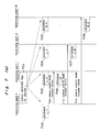
- the operation of the device control key processing sequence will be described hereinafter with reference to Fig. 7 (b).
- the operation in a case where the device control key has been operated by the remote control transmitter 640 when the remote control mode is the mode of the device 620 is as follows.
- the data code string reaches the remote control reception parts 616, 626, 636 by the infrared rays emitted from the remote control transmitter 640.
- the remote control mode at present is a mode of controlling the device 620
- the controlling operation is not effected upon its own device so as to transfer into the device 620 a frame with a device control order corresponding to the key code demodulated from the received data code string being provided as the contents.
- the present remote control mode is a mode for controlling its own device in the remote control reception part 626 of the device 620
- the contents of the control order of the data code string received from the remote control transmitter 640 are decoded to generate the device control signal to transfer it into the device system controller 622 of its own device so as to effect the given control.
- Any controlling operation is not effected upon the its own device as in the step 721 so as to transfer into the device 620 the frame with a device control order corresponding to the key code demodulated from the received data code string being provided as the contents.
- both the device control signal generated by way of the remote control reception part within the device 620 from the remote control transmitter 640, and the device control signal generated by the frame with the device control order transferred by way of the information transmission path from the other remote control reception part being provided as the contents are inputted into the device system controller 622.
- the processing contents are different in the contents of the control signal, the proper processing corresponding to the control signal is effected within the device system controller.
- the device system control roller 632 detects the operation thereof to renew the remote control mode of the remote control reception part 636 within the its own device into a mode of controlling the device 630.
- the remote control mode renewal notice frame is transferred with respect to all the other remote control reception parts connected with the system to notify that the remote control mode has been renewed into the mode for the controlling the device 630.
- the step described in the claim 2 of the present application is carried out to renew the remote control mode into a mode for controlling the device 630.
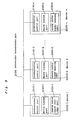
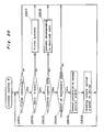
- Fig. 8 shows a block diagram of the station to which the present invention is applied.
- Reference numeral 2130 is an information transmission route for effecting the transmission of the information with each station constructing the AV system being connected.
- Reference numeral 2100 is a remote control signal reception part which is a portion the same as the remote control reception parts 2100 m-1 through 2100 m-n in the whole construction view shown in Fig. 9.
- Reference numeral 2101 is a light receiving means for converting the received infrared signal into the electric signal
- reference numeral 2102 is a demodulation means for converting the electric signal which has been converted by the light receiving means 2101 into the data code string in accordance with the specification defined in advance
- reference numeral 2103 is a data code processing means which divides the data code string generated by the demodulation means 2102, compares the contents with the previously defined data code table so as to examine whether or not the standard command corresponding to the reception data exists
- reference numeral 2104 is a format converting means for effecting the format conversion necessary for the transfer onto the information transmission path 2130 the reception command by the use of the standard commend when the standard command is judged to exist after the comparison thereof with the data code table.
- Reference numeral 2110 is a communication control part which is the portion the same as the communication control parts portions 2110 m-1 through 2110 m-n in the entire block diagram shown in Fig. 9.
- Reference numeral 2111 is a communication control means for effecting electric physical control so as to effect the data communication with the other station by way of the information transmission path 2130
- reference numeral 2112 is a frame generating means for generating a frame of a type necessary for sending the data of the information transmission path 2130 by way of the communication control means 2111.
- Reference numeral 2120 is a device function part, which is a portion corresponding to the device function parts 2120 m-1 through 2120 m-n in the entire block diagram shown in Fig. 9.
- Reference numeral 2121 is an original function part (for example, tuner, deck player part if it is VTR) of the station, reference numeral 2122 is a system control means for controlling the function operation of the station.
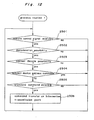
- the processing routine 1 shown in Fig. 12 is normally carried out.
- the step 2501 which is the initial step is processed by the light receiving means 2101 so as to check whether or not the remote signal has been received.
- a method of inspecting whether or not the remote control signal converted into the electric signal from the infrared ray signal has been outputted into the output part of the light receiving means 2101 is general.
- the processing operation of the processing routine 1 is finished on the assumption that no remote control signal has been received, and the operation returns to the start.
- some signal has been outputted into the output part of the light receiving means 2101, it is judged that the signal of the infrared ray remote control has been received, and the step goes to the step 2502.
- the step 2502 judges whether or not the received infrared ray remote control signal may be demodulated.
- demodulation means that the signal converted into the electric signal by the light receiving means 2101 after the reception is inverted into the data code string of the "0" or "1” by the demodulation means 2102 in accordance with the previously determined rule.
- the infrared ray remote control signal is composed of the combination of a high level signal (+5V by way of example of TTL level signal) to continue for the time of integer multiple of a certain unit time "T” and a low lever signal (OV by way of example of TTL level signal).
- a high level signal (+5V by way of example of TTL level signal) to continue for the time of integer multiple of a certain unit time "T”
- a low lever signal OV by way of example of TTL level signal.
- the demodulation is effected as the "header” meaning the head of the frame of the infrared ray remote control signal.
- the demodulation processing operation is effected to advance into the following step.
- the data code string demodulated by the demodulation means 2102 is divided into the bit unit defined previously.
- the contents of the respective words agree with the contents of the previously defined data table, it is possible to decode the contets.
- the remote control format example is shown in the (1), (2) of the data format example of Fig. 10.
- the remote control format example 1 of the (1) is a signal format (hereinafter it is referred to as A company format) used in the infrared ray remote control corresponding station of a certain company at the comparatively early stage.
- Reference numeral 2301 is a header showing the head of the frame
- reference numeral 2302 is a 5 bit of device code for the discrimination of the station
- reference numeral 2303 is a 6 bit of data code showing the contents of the control command.
- Reference numeral 2304 is an inversion bit of the 5 bit of device code, which is also 5 bits as in the device code
- reference numeral 2305 is an inversion bit of the data code, which is also 6 bits as in the data code
- reference numeral 2306 is a 1 bit of check bit for detection of the data transmission error by the infrared ray.
- the remote control format example 2 of the (2) is a recommendation format (hereinafter referred to as Household Electric Product Association) stipulated in the "Error Preventing Measure For Infrared Ray Remote Control Household Electric Product” (issued in July, 1987) by the Foundation Household Electric Product Association.
- Household Electric Product Association Format is recommended to be used when the remote control signal using the infrared ray is transmitted.
- Reference numeral 2311 is a header showing the head of the frame
- reference numeral 2312 is a 16 bit of maker code for discriminating the makers
- reference numeral 2313 is a 4 bit of parity code for preventing the reception error of the maker code
- reference numeral 2314 is a 12 bit of device code for discriminating the stations and so on.
- Reference numeral 2315 is a command/data code for transmitting the control command and the data, which is capable of a plurality of byte transfer with 8 bits as a unit.
- Reference numeral 2316 is a parity code for preventing the reception error of the device code and the command/data code.
- the data code string is divided into the bit unit previously defined as in the format example so as to check whether or not the contents corresponding to respective codes are defined in the table. It is judged that the contents may be decoded when the corresponding table exists, but the contents may not be decoded in cases except for it.
- the step advances to the next step 2504. Since the successive processing operation cannot be carried out when the contents has been judged to be impossible to be decoded, the received data are scraped so that the processing routine returns to the start thereof.
- the contents of the reception signal which has been judged to be decoded at the step 2503 are checked so as to judge whether the received infrared ray remote control signal is a command addressed to one's station or a command addressed to the other station.
- the judgement is effected with reference to the device code 2302 in the case of the A company format, and the judgement is effected with reference to the maker code 2312 and the device code 2314 in the case of the Household Electric Product Association format.
- the data received without any processing are scraped at the data processing means 2103 so that the processing returns to the start thereof.
- the reason why any processing is not effected is that the processing is carried out at the system control means 2122 when the signal is the command addressed to one's station, because the output of the demodulating means 2102 is transferred directly into the system control means 2122.
- the contents of the portion equivalent to the station control command in the data code string of the infrared ray remote control signal which has been judged to be addressed to the other station at the step 2504 are compared with the contents of the previously defined standard command table so as to advance to the next step 2506 when the corresponding standard command exists. Since the corresponding operation cannot be effected in the remote control method of the present invention when the standard command corresponding to the standard command table does not exist, the received data code string is scraped so that the processing returns to the head (the processing method is provided in the claim 12 of the present application when the standard command does not exist).
- the portion equivalent to the station control command in the data code string is the data code 2303 or a command/data code 2315 provided in the remote control format example of Fig. 10.
- the standard command means a command defined in the [84(Secretriat)86 I, II Draft - Domestic digital Bus].
- the conversion is effected into the standard command by the respective judgement processing up to the step 2505 so as to carry out the (1) command conversion, (2) format conversion and (3) transfer processing of the infrared ray remote control data which are ensured to become transferable into the other station.
- the portion equivalent into the station control command in the data code string of the infrared remote control data namely, the data code 3203 or the command/data code 2315 presented into the remote control format example of Fig. 10 is processed to be replaced into the command defined by the [84(Secretariat)86 I, II Draft - Domestic digital Bus].
- the station control command is defined by one word or one byte, with the above described standard command is composed of 1 byte of opecode and 1 byte of or a plurality of byte operands.
- the first section in the embodiment of the present invention The contents of the message field 1129 in the frame described in the paragraph of the form and the basic communication procedure of the (c) frame in the summary description of the system are defined in further detail in the [84(Secretariat)86 I, II Draft - Domestic digital Bus].
- One example thereof is presented in the (3) and the (4) of Fig. 10.
- the message field in Fig. 22 is the same as the message field 1129 of Fig. 3 (c), with the contents thereof being defined as in Fig. 10 (4).
- the information to be transmitted at first is the routining information (information showing that the command is going to send to which subdevice of which station from which subdevice of which station) composed of a ⁇ BEGIN> code 2331, an operand 2332 of the ⁇ BEGIN>, a SSDA (SOURCE SUB-DEVICE ADDRESS) 2333, and a DSDA (DESTINATION SUB-DEVICE ADDRESS) 2334.
- Reference numeral SSDA 2333 is an address showing the start subdevice of the command
- reference numeral DSDAS 2334 is an address showing the subdevice of the destination of the command.
- the actual command is transmitted next to the routing information.
- the standard command converted by the processing of the (1) command conversion is transferred in the form of the OPC (opecode) 2335 + OPR (operand) 2336. Therefore, the command received as the infrared ray remote control data is command-converted, is accommodated in this portion in the form of the OPC + OPR and is transferred.
- the final ⁇ END> code 2337 is a code showing the completion or the like of the command frame.
- the slave address 1115 and the DSDA 2334 showing the station address of the destination of the command
- the contents of the device code 2302 and the device code 2314 in the infrared ray remote control data are converted into the address defined in the [84(Secretariat)86 I, II Draft - Domestic digital Bus], and are accommodated.
- These format conversion processing is carried out by the format converting means 2104.
- the data code processing means 2103 and the format converting means 2104 described hereinabove are generally processed by the software by the use of the microprocessor.
- the command conversion processing and the format conversion processing are carried out so as to effect the re-configuration.
- This is the processing of transferring the other station control frame into the given other station by way of the communication control part 2110. Since the other transfer party and the transfer contents are already specified with the above described format conversion processing, these frames are transferred into the frame generating means 2112 so as to set the other paragraphs (mode bit 1112, master address 1113, control code 1138 and so on). Thereafter, the frame is transferred into the station destination by the way of the information transmission route 2130 by the function of the communication control means 2111.
- the infrared ray remote control data shown in Fig. 13 (1) As the example of the A company format, a case where the infrared ray remote control data shown in Fig. 13 (1) has been received will be taken into consideration.
- the infrared ray remote control signal received may be demodulated
- the infrared ray remote control data received may be decoded in contents
- the infrared ray remote control data received is not a command addressed to one's station
- the standard command corresponding to the infrared remote control signal received exists.
- the step moves to the step 2506 by the carrying out of the processing routine 1 so as to effect the following processing.
- the reception data is converted into the format of Fig. 10 (3) and (4) in accordance with the contents defined in the [84(Secretariat)86 I, II Draft - Domestic digital Bus], the respective data are determined as follows.
- mode bit 1112 depends on the function of the communication control means 2111, assume here that it is "mode 1".
- ⁇ Mode bit 1112> 01 (B)
- ⁇ Master address 1113> 100 (H).
- ⁇ Slave address 1115> 120 (H).
- a method defined in the [84(Secretariat)86 I, II Draft - Domestic digital Bus] is used as the method of determining the address. ( See Table 1)
- the BEGIN code 2331 through END code 2337 are accommodated in the message field 1129. Although the illustration is omitted from the BEGIN code 2331 among them, because the method of determining of DSDA 2334 is not necessary especially for the understanding of the present invention, the application of the definition of the [84(Secretariat)86 I, II Draft - Domestic digital Bus] becomes as follows.
- ⁇ BEGIN2331> BD (HD)
- ⁇ OPR2332 of the BEGIN> 54 (H)
- ⁇ SSDA2333> C8 (H)
- ⁇ DSDA2334> 20 (H)
- the step 2601 which is the initial step thereof is processed by the light receiving means 2101 so as to check whether or not the remote control signal has been received. Since the checking means and the processing method are completely the same as the step 2501 in the processing of the remote control method of the claim 4 of the present application, the description of the processing method and so on are omitted.
- the processing of the processing routine 2 is completed to return to the start.
- the step advances into the step 2602.
- step 2602 it is judged whether or not the signal of the received infrared ray remote control may be demodulated. Since the meaning of the "demodulation” and “possible demodulation” and the judgement method are completely the same as the step 2502 in the processing of the remote control method of the claim 11 of the present application, the description of the processing method and so on are omitted.
- the processing is completed here to return to the start of the processing routine 2.
- the demodulation processing operation is effected so as to advance to the next step.
- the step 2603 it is judged whether or not the contents of the signal demodulated by the demodulation means 2102 may be decoded. Since the meaning of the decoding of the contents and the contents decoding method are completely the same as the step 2503 in the processing of the remote control method described in the claim 11 of the present application, the description of the processing method and so on are omitted.
- the step advances to the next step 2604.
- the (1) format conversion and the (2) transfer processing are effected so as to transfer to the other station, as the transparent (transmitting) data, the contents of the reception signal which has been judged to be impossible to be decoded in the contents at the step 2603.
- the processing of the format conversion is effected within the format conversion means 2104.
- the procedure of the format conversion is classified into the following five processings.
- a format which is not a system of 8-bit unit like 5 bits in the device code and 6 bits in the data code as in Fig. 10 (1), a format which is a system of 8-bit unit (or may be easily re-divided into 8-bit unit), and so on are mixed in the code system of the infrared ray remote control data. But in the frame on the information transmission path, the format has the data transmitted in the 8-bit unit, so that the unit is converted into the 8-bit unit in the case of the code system which is not 8 bits in unit.
- the unit is divided into the 8-bit unit by the procedure 2, thus generating insufficient bit on the last byte.
- the dummy bit is added by the insufficient number of the bits, so that such processing as may be converted correctly into the 8-bit unit may be effected.
- a ⁇ format classification> identifier for identifying which format of remote control data it is is added so as to display the type of the format.
- the data field part generated by the processings of the procedure 1 through the procedure 4 are transferred into the frame generating means 2112 of the communication control part 2120 so as to compose the frame to be transmitted into the information transmission route 2130.
- the processing of the format conversion is completed by the above described processing.
- the re-configuration is effected by the execution of the command conversion processing and the format conversion processing.
- the other station control frame is transferred into all the stations connected with the information transmission path by way of the communication control part 2110.
- the processing routine 2 returns to the head thereof so as to prepare for the reception of the next infrared remote control data.
- the concrete example will be described with reference to Fig. 15.
- the reception of the data of the A company format will be described by way of example.
- the infrared ray remote control data shown in Fig. 15 (1) has been received is taken into consideration.
- the step advances to the step 2604 so as to carry out the next processing.
- step 604 is processed by the following procedure as described in the paragraph of "(b) operation".
- the format of the infrared ray remote control data is composed as in the (1) and (2) of Fig. 10 as described in the description of the embodiment of the claim 11 of the present application, with headers 2301, 2311 and trailers 2307, 2317 except for data necessary for the station control being attached. They are attached for recognition of the head and the end of the frame of the infrared ray remote control data, and are portions unnecessary in a case where the transferring operation is effected by the use of the frame of the other format into the other station.
- these headers 2301, 2311 and trailers 2307, 2317 are eliminated, and the portions (device code 2302, data code 2303, device code inversion bit 2304, data code inversion bit 2305, check bit 2306) necessary for the transferring operation into the other station are extracted.
- Procedure 2 and Procedure 3 Division into 8-bit unit and addition of the dummy bit
- a format which is not a system of 8-bit unit like 5 bits in the device code and 6 bits in the data code as in Fig. 10 (1), a format which is a system of 8-bit unit (or may be easily re-divided into 8-bit unit), and so on are mixed in the code system of the infrared ray remote control data. But in the frame on the information transmission path, the format has the data transmitted in the 8-bit unit, so that the unit is necessary to be converted into the 8-bit unit in the case of the code system which is not 8 bits in unit.
- a method of dividing the infrared ray remote control data of the above described A company format into the 8-bit unit is shown in the procedure (2) of Fig. 15.
- the device code 2302 a method of arranging the device code 2302, the data code 2303, the device code inversion bit 2304, the data code inversion bit 2305 and the check bit 2306 in one row so as to divide it from the head 8 bits by 8 bits.
- the infrared ray remote control data totaled in all do not become the multiple of the 8 bits.
- the dummy bits are accommodated by the number of the bits which is insufficient for the division into the 8-bit unit.
- the dummy bit may be neither "0" nor "1".
- the dummy bit 2350 is accommodated into the portion of the insufficient bit.
- the "0" is accommodated in the portion of the dummy bit 2350.
- the ⁇ format classification> identifier 2342 for recognizing which format the remote control data comes from is added.
- the data field part generated by the processing of the procedure 1 through the procedure 4 is transferred into the frame generating means 2112 so as to effect the transfer processing.
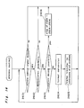
- Fig. 16 shows a block diagram of the station to which the receiver of the remote control apparatus described in the claim 13 of the present application is applied.
- Reference numeral 2130 is an information transmission path for the transmission of the information with the respective stations for constructing the AV system being connected.
- Reference numeral 2100 is a remote control signal reception part, which is the same as the remote control reception parts 2100m-1 through 2100m-n in the whole block diagram shown in Fig. 9.
- Reference numeral 2101 is a light receiving means for converting the received infrared ray signal into the electric signals
- reference numeral 2102 is a demodulating means for converting the electric signals converted by the light receiving means 2101 into the data code string in accordance with the specification previously defined
- reference numeral 2103 is a data code processing means for dividing into the significant data unit the data code string generated by the demodulating means 2102, comparing the contents with the data code table previously defined so as to check whether or not the standard command corresponding the reception data exists
- reference numeral 2104 is a format converting means for effecting the format conversion necessary for the transferring operation of the reception command on the information transmission path 2130 by the use of the standard command when the standard command has been judged to exit through the comparison with the data code table.
- Reference numeral 2140 is a device search means for searching the station address of the station to be connected with the information transmission path 2130 and the maker code so as to effect the registering process
- reference numeral 2141 is an address table for registering the station address searched by the device search means 2140 and the maker code
- reference numeral 2142 is a maker code comparing means for comparing the maker code contained in the received infrared ray remote control data with the maker code to be registered in the address table so as to pass into the frame generating means 2112 the consistent station address.
- Reference numeral 2110 is a communication control part, which is the same portion as the communication control parts 21110m-1 through 2110m-n in the whole block diagram shown in Fig. 9.
- Reference numeral 2111 is a communication control means for effecting the electric physical control for effecting the data communication with the other station by way of the information transmission path
- reference numeral 2112 is a frame generating means for generating the frame of a form necessary to send the data into the information transmission path 2130 by way of the communication control means 2111.
- Reference numeral 2120 is a device function part, which is a portion equivalent to the device function parts 2120m-1 through 2120m-n of the whole block diagram shown in Fig. 9.
- Reference numeral 2121 is an original function part (for example, a tuner or deck player part if it is VTR) of the station, reference numeral 2122 is a system control means for controlling the function operation of the station.
- Fig. 17 is an address table for registering the station address of the station connected with the information transmission path 2139 and the maker code.
- Reference numerals 2150, 2151, ... are station address accommodating regions for accommodating the station address values of the station connected with the information transmission path 2130
- reference numerals 2160, 2161, ... are maker code accommodating regions for accommodating the maker codes with the manufacturing maker of the station connected with the information transmitting path 2130 being coded.
- the maker codes 2160, 2161, ... correspond respectively to station addresses 2150, 2151, ... .
- the receiver of the remote control apparatus of the claim 13 of the present application is processed down to the step 2604.
- a method of determining the opposite station of the frame for transferring onto the information transmission path 2130 is provided.
- each station connected previously with the information transmission path 2130 is required to search which maker it is so as to register on the address table 2141. The method thereof will be described at first.
- the processing of the frame sending is effected by the frame generating means 2112 and the communication control means 2111.
- the affirmative reply is returned as the ACK bit 1117 of the slave field 1127 with respect to the frame, it is judged the station of the address of the set contents in the salve address bit 1115 is connected onto the information transmission path 2130, so that it is accommodated in the station address accommodation region 2150 (2151, ...) of the address table 2143.
- the value of the address which has been set in the slave address bit 1115 in the above description is increased by one so as to effect the similar processing.
- the addresses of all the stations connected onto the information transmission path 2130 may be accommodated into the station address accommodation regions 2150, ... of the address table 2143.
- the maker code is inquired with respect to the station registered in the station address accommodation area 2150 of the address table 2141, and the reply contents thereof are registered in the maker code accommodation region 2160.
- the construction of the frame for the inquires about the maker codes is not defined here, because it is defined particularly. Although the contents of the maker code may be defined anyway, the use of the maker codes defined as one portion of the Household Electric Product Association remote control format simplifies the later processing.
- the inquiry processing about the maker code is effected on all the stations accommodated in the station address accommodation region and is accommodated in the respective corresponding maker code accommodated regions.
- step 2704 from the step 2701 in the processing sequence chart of Fig. 18 is completely the same as the step 2604 from the step 2601 of the processing contents of the remote control method of the claim 5 of the present application, the description thereof will be omitted.
- the step 2705 it is judged whether the received remote control data is a Household Electric Product Association remote control format or the other format.
- the processing of the claim 12 of the present application is effected, because the the following procedure cannot be applied.
- the step goes to the step 2706.
- the other transfer party of the frame is determined in accordance with the registration contents of the address table 2141.
- the maker code 2312 is defined in the contents of the frame.
- the contents of the maker code is standardized by the Household Electric Product Association.
- the maker code of the received infrared ray remote control data is compared with the maker code accommodated in the maker code accommodation regions 2160, ... of the address table 2143.
- the station addresses accommodated in the station address accommodation regions 2150, ... corresponding to the maker code accommodation regions 2160, ... are assumed to become a slave address bit 1115 so as to hand over it, together with the data field generated by the step 2704, to the frame generating means 2112.
- a frame to be sent to the information transmission path 2130 is generated by the frame generating means 2112 so as to send it into the information transmission 30 by way of the communication control means 2111.
- This processing is executed with respect to all the stations registered in the address table 2141 so as to send a frame which has the same data field with respect to all the station, whose maker codes being in conformity.
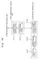
- Fig. 19 shows a block diagram of the station to which the remote control method described in the claim 14 of the present application is applied.
- Reference numeral 2130 is an information transmission path for effecting the transmission of the information with each station constituting the AV system being connected.
- Reference numeral 2110 is a communication control part, which has the same portions as the communication control part 2110m-1 through 2110m-n in the whole block diagram shown in Fig. 9.
- Reference numeral 2111 has a communication control means for effecting the electric physical control in order to effect the data communication with the other station by way of the information transmitting path
- reference numeral 2113 is a frame decoding means for analyzing the frame received by way of the communication controlling means 2111 from the information transmission path 2130 down to the usable form by the device function part 2120 to be described hereinafter.
- Reference numeral 2120 is a device function part, which is portions corresponding to the device function parts 2120m-1 through 2120m-1 of the whole block diagram shown in Fig. 9.
- Reference numeral 2121 is the original function part (for example, a tuner or a deck player part if it is a VTR) of the station.
- Reference numeral 2122 is a system control means for controlling the functional operation of the station, reference numeral 2123 is a format inverse conversion means for converting it into a signal for controlling the system controlling means 2122 from the frame analyzed by the frame decoding means 2113.
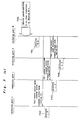
- the operation of the remote control method of the claim 14 of the present application will be described in detail hereinafter with reference to the processing flow charts Fig. 19 and Fig. 20.
- the processing contents to be described hereinafter are carried out within the format inverse converting means 2123 in the block diagram of Fig. 19.
- the contents described in the claim 14 of the present application is a procedure in which the station which has received the frame transferred onto the information transmission path 2130 by the use of the remote control method of the claim 12 of the present application effects the inverse conversion (format inverse conversion) of the frame into the contents wherein the system controlling means 2122 may be operated.
- the step 2801 which is the first step checks whether or not the frame has been received from the information path 2130. The check is carried out within the frame decoding means 2113. When the frame has not been received from the information transmission path 2130, the processing is completed without effecting the operation, and the processing routine 4 returns to the head thereof. When some frame has been received from the information transmission path 2130, the step advances to the step 280.
- the construction of the frame the frame decoding means 2113 receives from the information transmission path 2130 is received in the shape of the format (5) of Fig. 15.
- the contents of the control code 2325 are checked to judge whether the received frame is a data frame or the other frame.
- the step advances to the step 2807. Since the processing contents at the step 2807 are beyond the scope of the present invention, the description thereof is omitted.
- the frame decoding means 2113 extracts only the portion of the data field from the received data frame to transform it into a shape shown in the format (4) of Fig. 15 and advances to the step 2803.
- the step the contents of the ⁇ data classification> identifier 2341 of the frame shown in the format (4) of Fig. 15 is checked to examine whether or not the received data frame is the remote control data.
- the step advances to the step 2808. Since the processing contents at the step 2808 are beyond the scope of the present invention, the description thereof will be described.
- the step advances to the step 2804.
- the step advances to the step 2805.
- the received frame is discarded to complete the processing and the processing returns to the head of the processing routine 4.
- the received remote control data frame is set to the format designated by the format classification 2342 so as to re-configure the remote control data.
- the remote control data re-configured at the step 2805 is transferred with respect to the system control means 2122.
- the reason why the signal to be sent to the system control means 2122 is put into the remote control data form is that means such as software and so on for decoding the remote control data and effecting the necessary control is already prepared within the system control means 2122. If the circumstances require, the contents of the remote control data are decoded and the function part 2121 may be directly controlled.
- the received remote control data frame is set to the format specified by the format classification 2342 so as to re-configure the remote control data.
- the first processing at the step is that the received data 1 through data 3 is bit-divided in accordance with the format specified by the ⁇ format classification>2342. Since the A company format shown in the example is composed of a device code 5 bits 2302, a data code 6 bits 2303, a device code inversion bit 5 bits 2304, a data code inversion bit 6 bits 2305, a check bit 1 bit 2306, the received data are divided into 5 bits, 6 bits, 5 bits, 6 bits, 1 bit from the head. When the above described re-division has been effected, the bit left over last is judged to be the dummy bit 2350 and is deleted. In this example, one bit is deleted as the dummy bit (see Fig. 15 (2)).
- a head 2301 is added before the device code 2302, the trailer 2307 is added after the check bit 2302 so as to complete the remote control data frame of the A company format.
- the processing at this step is different in the method or the like of re-dividing of the bit row by the contents specified by the ⁇ format classification> 2342.
- the receiver of the remote control roll apparatus has been built in in each device in all the embodiments, it may be constructed as a separate member in the system in addition to the above description.
Landscapes
- Physics & Mathematics (AREA)
- General Physics & Mathematics (AREA)
- Engineering & Computer Science (AREA)
- Computer Networks & Wireless Communication (AREA)
- Signal Processing (AREA)
- Selective Calling Equipment (AREA)
Applications Claiming Priority (4)
| Application Number | Priority Date | Filing Date | Title |
|---|---|---|---|
| JP108852/89 | 1989-04-27 | ||
| JP10885289A JPH02288497A (ja) | 1989-04-27 | 1989-04-27 | リモートコントロール装置送信機とリモートコントロール装置受信部とリモートコントロール方法 |
| JP33057789A JPH0710117B2 (ja) | 1989-12-20 | 1989-12-20 | リモートコントロール方法 |
| JP330577/89 | 1989-12-20 |
Publications (3)
| Publication Number | Publication Date |
|---|---|
| EP0395097A2 true EP0395097A2 (de) | 1990-10-31 |
| EP0395097A3 EP0395097A3 (de) | 1991-01-23 |
| EP0395097B1 EP0395097B1 (de) | 1995-08-16 |
Family
ID=26448662
Family Applications (1)
| Application Number | Title | Priority Date | Filing Date |
|---|---|---|---|
| EP19900108095 Expired - Lifetime EP0395097B1 (de) | 1989-04-27 | 1990-04-27 | Fernsteuersystem für Audio/Video-Geräte |
Country Status (2)
| Country | Link |
|---|---|
| EP (1) | EP0395097B1 (de) |
| DE (1) | DE69021620T2 (de) |
Cited By (3)
| Publication number | Priority date | Publication date | Assignee | Title |
|---|---|---|---|---|
| EP0605134A2 (de) * | 1992-12-28 | 1994-07-06 | Sony Corporation | Ton- und Bildsystem |
| EP0612157A2 (de) * | 1993-01-06 | 1994-08-24 | Sony Corporation | Verfahren zur Fernsteuerung von mehreren Audiovisuelgeräten |
| WO1997004431A1 (en) * | 1995-07-17 | 1997-02-06 | Gateway 2000, Inc. | Remote control device for an entertainment system |
Citations (3)
| Publication number | Priority date | Publication date | Assignee | Title |
|---|---|---|---|---|
| DE3106427A1 (de) * | 1980-02-26 | 1982-03-04 | Nippon Electric Co., Ltd., Tokyo | Fernbedienungssender |
| EP0223311A2 (de) * | 1985-11-19 | 1987-05-27 | Koninklijke Philips Electronics N.V. | Fernsteuersystem |
| GB2197104A (en) * | 1986-10-24 | 1988-05-11 | Sony Corp | Remotely-controllable electronic apparatus including video systems |
-
1990
- 1990-04-27 DE DE1990621620 patent/DE69021620T2/de not_active Expired - Fee Related
- 1990-04-27 EP EP19900108095 patent/EP0395097B1/de not_active Expired - Lifetime
Patent Citations (3)
| Publication number | Priority date | Publication date | Assignee | Title |
|---|---|---|---|---|
| DE3106427A1 (de) * | 1980-02-26 | 1982-03-04 | Nippon Electric Co., Ltd., Tokyo | Fernbedienungssender |
| EP0223311A2 (de) * | 1985-11-19 | 1987-05-27 | Koninklijke Philips Electronics N.V. | Fernsteuersystem |
| GB2197104A (en) * | 1986-10-24 | 1988-05-11 | Sony Corp | Remotely-controllable electronic apparatus including video systems |
Non-Patent Citations (1)
| Title |
|---|
| FUNKSCHAU, no. 17, 1987 Munich HERBERT HAFNER "Von der Fern- bedienung zur Lernbedienung" pages 20-24 * |
Cited By (10)
| Publication number | Priority date | Publication date | Assignee | Title |
|---|---|---|---|---|
| EP0605134A2 (de) * | 1992-12-28 | 1994-07-06 | Sony Corporation | Ton- und Bildsystem |
| EP0605134A3 (de) * | 1992-12-28 | 1996-02-07 | Sony Corp | Ton- und Bildsystem. |
| US5802300A (en) * | 1992-12-28 | 1998-09-01 | Sony Corporation | Audio video system |
| EP0612157A2 (de) * | 1993-01-06 | 1994-08-24 | Sony Corporation | Verfahren zur Fernsteuerung von mehreren Audiovisuelgeräten |
| EP0612157A3 (de) * | 1993-01-06 | 1994-11-23 | Sony Corp | Verfahren zur Fernsteuerung von mehreren Audiovisuelgeräten. |
| US5488357A (en) * | 1993-01-06 | 1996-01-30 | Sony Corporation | Remote controlling method and system feature starting method and controlling method for audio/visual system |
| EP0810739A2 (de) * | 1993-01-06 | 1997-12-03 | Sony Corporation | Verfahren zur Inbetriebnahme einer Systemfunktion eines audiovisuelles Systems und deren Steuerung |
| EP0810739A3 (de) * | 1993-01-06 | 1998-05-13 | Sony Corporation | Verfahren zur Inbetriebnahme einer Systemfunktion eines audiovisuelles Systems und deren Steuerung |
| WO1997004431A1 (en) * | 1995-07-17 | 1997-02-06 | Gateway 2000, Inc. | Remote control device for an entertainment system |
| US5900867A (en) * | 1995-07-17 | 1999-05-04 | Gateway 2000, Inc. | Self identifying remote control device having a television receiver for use in a computer |
Also Published As
| Publication number | Publication date |
|---|---|
| DE69021620D1 (de) | 1995-09-21 |
| EP0395097B1 (de) | 1995-08-16 |
| EP0395097A3 (de) | 1991-01-23 |
| DE69021620T2 (de) | 1996-01-18 |
Similar Documents
| Publication | Publication Date | Title |
|---|---|---|
| US5182551A (en) | Remote control system for audio/video devices | |
| US5291343A (en) | Audio/video system for television receiver, video cassette recorder, and so forth | |
| US5132679A (en) | Remote control system for a plurality of controlled devices | |
| US4623887A (en) | Reconfigurable remote control | |
| US5654714A (en) | Remote controller and method for presetting control data therein | |
| EP0124331B2 (de) | Fernbedienungssendervorrichtung zur Steuerung eines oder mehrerer Fernsehgeräte | |
| EP0455549A2 (de) | Übertragungssystem zur Fernbedienung von elektronischen GerÀ¤ten | |
| US5313408A (en) | Multistation display system for controlling a display monitor associated with plural audio video devices | |
| EP0627823B1 (de) | Kommunikationsprotokole zur Übertragung von Steuerdaten | |
| US7272389B2 (en) | Wireless communication apparatus for use in communication using identification data | |
| CN100385946C (zh) | 显示彩色的音频/视频节目的方法和装置 | |
| US5128668A (en) | Remote-controlled electronic equipment with a transmitting function | |
| EP0610630B1 (de) | Bidirektionales Bus und zugehörige Sende-, Empfangs- und Kommunikationsverfahren | |
| EP0371749A2 (de) | Audio/Videosystem für Fernsehempfänger, Videokassettenrekorder, und so weiter | |
| EP0395097A2 (de) | Fernsteuersystem für Audio/Video-Geräte | |
| EP0482953B1 (de) | Verfahren und System zur Datenübertragung in einem Übertragungsnetz in Kraftfahrzeugen | |
| US6088726A (en) | Address assignment system for extracting unused assignment addresses from a communication frame circulating among communication stations | |
| EP0531405B1 (de) | Rundfunkempfängersystem | |
| US6470012B2 (en) | Communication system and data-format to be used in the same | |
| US6602001B1 (en) | Remote control system and remote control transmitter for use in the same | |
| EP0482959B1 (de) | System zur Datenübertragung | |
| CN100562059C (zh) | 电子设备及其控制方法 | |
| US20010028645A1 (en) | Apparatus control method and transmission device | |
| EP0683959B1 (de) | Lokales nachrichtensystem und station zur anwendung in einem solchen system | |
| JP2002252887A (ja) | リモコン送信器のカスタマイズ装置及びカスタマイズ方法 |
Legal Events
| Date | Code | Title | Description |
|---|---|---|---|
| PUAI | Public reference made under article 153(3) epc to a published international application that has entered the european phase |
Free format text: ORIGINAL CODE: 0009012 |
|
| AK | Designated contracting states |
Kind code of ref document: A2 Designated state(s): DE FR GB |
|
| PUAL | Search report despatched |
Free format text: ORIGINAL CODE: 0009013 |
|
| AK | Designated contracting states |
Kind code of ref document: A3 Designated state(s): DE FR GB |
|
| 17P | Request for examination filed |
Effective date: 19901201 |
|
| RHK1 | Main classification (correction) |
Ipc: H03J 9/00 |
|
| 17Q | First examination report despatched |
Effective date: 19930709 |
|
| GRAA | (expected) grant |
Free format text: ORIGINAL CODE: 0009210 |
|
| AK | Designated contracting states |
Kind code of ref document: B1 Designated state(s): DE FR GB |
|
| REF | Corresponds to: |
Ref document number: 69021620 Country of ref document: DE Date of ref document: 19950921 |
|
| ET | Fr: translation filed | ||
| PLBE | No opposition filed within time limit |
Free format text: ORIGINAL CODE: 0009261 |
|
| STAA | Information on the status of an ep patent application or granted ep patent |
Free format text: STATUS: NO OPPOSITION FILED WITHIN TIME LIMIT |
|
| 26N | No opposition filed | ||
| REG | Reference to a national code |
Ref country code: GB Ref legal event code: IF02 |
|
| PGFP | Annual fee paid to national office [announced via postgrant information from national office to epo] |
Ref country code: DE Payment date: 20070419 Year of fee payment: 18 |
|
| PGFP | Annual fee paid to national office [announced via postgrant information from national office to epo] |
Ref country code: GB Payment date: 20070425 Year of fee payment: 18 |
|
| PGFP | Annual fee paid to national office [announced via postgrant information from national office to epo] |
Ref country code: FR Payment date: 20070411 Year of fee payment: 18 |
|
| GBPC | Gb: european patent ceased through non-payment of renewal fee |
Effective date: 20080427 |
|
| PG25 | Lapsed in a contracting state [announced via postgrant information from national office to epo] |
Ref country code: DE Free format text: LAPSE BECAUSE OF NON-PAYMENT OF DUE FEES Effective date: 20081101 |
|
| REG | Reference to a national code |
Ref country code: FR Ref legal event code: ST Effective date: 20081231 |
|
| PG25 | Lapsed in a contracting state [announced via postgrant information from national office to epo] |
Ref country code: FR Free format text: LAPSE BECAUSE OF NON-PAYMENT OF DUE FEES Effective date: 20080430 |
|
| PG25 | Lapsed in a contracting state [announced via postgrant information from national office to epo] |
Ref country code: GB Free format text: LAPSE BECAUSE OF NON-PAYMENT OF DUE FEES Effective date: 20080427 |