EP0394069A2 - Induktive Modulatoranordnung - Google Patents
Induktive Modulatoranordnung Download PDFInfo
- Publication number
- EP0394069A2 EP0394069A2 EP90304297A EP90304297A EP0394069A2 EP 0394069 A2 EP0394069 A2 EP 0394069A2 EP 90304297 A EP90304297 A EP 90304297A EP 90304297 A EP90304297 A EP 90304297A EP 0394069 A2 EP0394069 A2 EP 0394069A2
- Authority
- EP
- European Patent Office
- Prior art keywords
- coil
- coils
- source
- signals
- carrier
- Prior art date
- Legal status (The legal status is an assumption and is not a legal conclusion. Google has not performed a legal analysis and makes no representation as to the accuracy of the status listed.)
- Withdrawn
Links
Images


Classifications
-
- H—ELECTRICITY
- H03—ELECTRONIC CIRCUITRY
- H03C—MODULATION
- H03C3/00—Angle modulation
- H03C3/10—Angle modulation by means of variable impedance
- H03C3/12—Angle modulation by means of variable impedance by means of a variable reactive element
- H03C3/18—Angle modulation by means of variable impedance by means of a variable reactive element the element being a current-dependent inductor
-
- H—ELECTRICITY
- H03—ELECTRONIC CIRCUITRY
- H03C—MODULATION
- H03C1/00—Amplitude modulation
- H03C1/08—Amplitude modulation by means of variable impedance element
- H03C1/10—Amplitude modulation by means of variable impedance element the element being a current-dependent inductor
-
- H—ELECTRICITY
- H03—ELECTRONIC CIRCUITRY
- H03C—MODULATION
- H03C1/00—Amplitude modulation
- H03C1/52—Modulators in which carrier or one sideband is wholly or partially suppressed
- H03C1/60—Modulators in which carrier or one sideband is wholly or partially suppressed with one sideband wholly or partially suppressed
Definitions
- This invention relates to inductive modulator systems.
- modulation Placing information in the form of electrical signals, usually in the audio ranges, onto a much higher frequency signal for the purpose of transmitting that information through space is called modulation.
- Radio and television transmission at different assigned frequencies or narrow frequency bands, determined by the higher frequency signal (the carrier frequency) is detected at the receiving end by tuning the receiver to the desired frequency band.
- the signals then are "demodulated" to provide the audio signals or other electrical signals at the receiver.
- the signal which is being modulated is a sine wave signal of constant amplitude.
- the signal which then varies some parameter of this sine wave carrier signal is known as the modulating signal.
- Amplitude modulation of a carrier signal is widely used; and the particular form has different subdivisions, such as double sideband (DSB), signal sideband (SSB), variable sideband (VSB), and others. Circuits for providing these different types of modulation are common and well known.
- DSB double sideband
- SSB signal sideband
- VSB variable sideband
- Circuits for providing these different types of modulation are common and well known.
- simple amplitude modulation typically there are two sidebands generated (DSB) and each of these sidebands contains approximately one-sixth (1/6th) of the total power. At the receiver, only one of the two sidebands is used to demodulate the signal. The energy or power in the other sideband is wasted.
- Single sideband transmission without a carrier is a relatively efficient transmission technique, but it is complex and requires extensive circuits and phase and frequency matching to reinsert the carrier at the receiver prior to demodulation of the desired modulating signal.
- Single sideband transmission may be considered a simple frequency translation of the baseband (information) or modulating signal to a higher frequency more suitable for propagation from a transmitter to a receiver.
- the known amplitude modulation systems typically have a limit on the relative strength of the modulating signal to the strength of the carrier signal. This limit is consdered 100% modulation, that is, the modulating signal, cannot exceed the strength of the carrier signal.
- the power of the carrier signal is selected in accordance with desired transmitting characteristics, and the modulating signal (which contains the desired information) is a relatively small fraction of the carrier signal.
- phase and frequency modulation transmission enjoy advantages over amplitude modulation transmission, primarily in the relative freedom from static and other signal distortion which occurs in amplitude modulation transmission due to weather conditions and other factors.
- the basic underlying techniques for combining the carrier signal and the modulating signal (the desired information signal) are similar, regardless of which type of modulation is employed.
- the carrier signal is selected to be of a higher power than the modulating or information signal.
- Typical transmitting stations whether for AM transmission, FM transmission, or television transmission, operate at extremely high power levels.
- the transmitting power is many thousands of watts. Consequently, the transmitting station equipment is necessarily expensive because of the high power requirements of all of the components used to produce and transmit the radio frequency signals.
- the basic cost of electricity used by such stations is very high and constitutes a significant percentage of the expense of operating the stations.
- Typical transmitting stations combine the various signals together, prior to transmission, through the use of active amplifier and active electronic mixing devices. Multiple plate vacuum tubes and similar components are utilized for this purpose. Because of the high power requirements, the electronic components are large and expensive. The high power requirements also subject transmitting stations to relatively high maintenance requirements. Typically, maintenance engineers are actively on duty during at least a major portion of the transmitting day.
- alternating current flows through a conductive coil (any coil)
- the current first flows in one direction through the coil for one half-cycle of the driving alternating voltage and then flows in the opposite direction through the other half-cycle of the alternating driving voltage.
- the first half of the positive half-cycle is an acceleration voltage and the other half of the positive half-cycle is a deceleration voltage.
- the voltage starts at zero and then increases to a peak at the mid point of the first half-cycle and then decreases back to zero to complete such a half-cycle.
- the following opposite half-cycle is the same, except that the acceleration-peak-deceleration voltage is exactly reversed in direction from that of the preceeding half-cycle.
- the charge carrier motion of this current generates a magnetic field, which is at right angles to the direction of the charge carrier motion in the wire of the coil. Consequently, the coil is surrounded by a magnetic flux with a north/south orientation at any given moment of time. This orientation is dependent upon the direction of the current in the coil.
- the coil has a permanent non-varying north/south orientation. This is the same as the magnetic flux or magnetic field around a flat circular ceramic magnet which has a hole in its center.
- a torodial coil energized by a DC current.
- the amount of current (power) necessary to cause a coil to have the same magnetic flux intensity (gauss intensity) as a given ceramic magnet intensity is very high. Consequently, the use of a ceramic magnet instead of a coil represents great savings in the amount of power necessary to produce the same magnetic effect.
- the direction of this movement determines if the top of the coil is a magnetic "north" pole or is a “south” pole, and the north/south orientation is at right angles to the direction of the charge carriers or electron flow in the wire of coil. Even a single electron in a circular orbit produces a magnetic dipole with a north/south orientation. This orientation is at right angles to the orbit of the electron as determined by the relative direction of the movement of the electron in such orbit.
- SSB single sideband
- a feature of this invention is the provision of an improvded modulation system which employs inductive modulation to combine a modulating signal with a carrier signal for simultaneously producing different types of modulation on the carrier, one or more of which may be selected for subsequent transmission.
- an inductive modulator system includes a source of carrier input signals and a source of information input signals.
- a first coil is connected to the source of carrier input signals and a second coil then is inductively coupled to the first coil and has the source of information input signals connected to it.
- a third output coil is inductively coupled to the first and second coils to provide a modulated output signal, as a result of the carrier input signals and infroamtion input signals supplied to the first and second coils.
- FIG. 1 is a block diagram of a magnetic induction modulation system in accordance with the preferred embodiment of the invention.
- the system includes a conventional radio frequency carrier oscillator 10 which operates at the desired RF transmission frequency, or at subharmonic of that frequency.
- the oscillator 10 is conventional and supplies its output signals to a suitable amplifier 12, also of conventional configuration.
- the output of the amplifier 12 is supplied through a shaping circuit, which typically comprises a half-wave or rectifier circuit for producing half-wave or uni-polar signals at the carrier oscillator frequency.
- These signals may be either the positive or negative half cycles of the alternating signal produced by the carrier oscillator and supplied through the amplifier 12. Thus, they constitute a pulsating direct current (DC) carrier.
- DC direct current
- the output of the shaping circuit 13 then is applied to the central toroidal core 14 of three inductively coupled cores 14, 20 and 22, as illustrated most clearly in Figures 1 and 2.
- the current through the core 14 constitutes a sequence of half-wave pulses, such as the pulses A, shown in Figure 7.
- the flux through the core 14 is a constantly changing uni-polar flux having magnetic field pattern corresponding to the amplitude pattern of Figure 7A, matching the changes in current produced at the output of the shaping circuit 13.
- Suitable input signals such as audio signals
- a microphone 16 Suitable input signals, such as audio signals, are detected by a microphone 16 and are supplied through an audio input circuit 18 and an audio amplifier 19, which are of conventional configurations.
- the output of the audio amplifier 19 then is applied to the terminals of the toroidal coil 20.
- the frequency variations of the signals supplied to the coil 20 from the audio amplifier 19 are much lower than the frequency of the signals supplied to the coil 14.
- the coils 14 and 20, as well as an output totoidal coil 22, all are placed in close physical proximity to one another, so that the inductive magnetic fields of these various coils interact, that is, each of the coils are placed in the inductive fields of the others.
- the effect of this is to produce multiple modulations of the carrier 14 as picked up on the output ciol 22.
- the half-wave carrier is reproduced in the coil 22; but it is modulated by the signals supplied to the coil 20 in phase (or angle), frequency, and in amplitude. All of these modulations simultaneously exist in the composite output signal produced by the coil 22; and all of these signals are unidirectional or uni-polar, not double sideband.
- Figures 7D and 7E are the mirror images of each other, with the difference caused by rotating the coil 22 with respect to the coil 14 by 180° to achieve the selected waveform of either Figure 7D or 7E.
- the carrier is subjected to phase or angle modulation, as indicated in the dotted line waveform shown in Figure 7C. Both amplitude and angle modulation are present as well as the carrier wave. Note, in Figures 7D and 7E, that about 5% of the carrier is below the zero line, which preserves the frequency of the signal without having to re-insert it at the receiver.
- this angle modulation may be converted to FM modulation by supplying the signal through a suitable filter (such as the filter 74) to convert the angle modulation to FM modulation.
- a suitable filter such as the filter 74
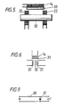
- This may comprise a standard technique in the form of a simple network circuit of the type comprising a resistor 80 and a capacitor 81, as shown in Figure 9.
- the filter 24 which is connected to the output of the output coil 22 selects the desired type of modulation which is to be transmitted from the transmitting station.
- the output of the filter 24 is applied to a pair of cascaded, conventional, linear amplifier circuits 25 and 26 to provide an amplified signal for an antenna matching circuit 28.
- the output of the circuit 28 is supplied to a suitable transmitting antenna 30 which transmits the uni-polar pulsating signal (or combination of signals) desired from the transmitting station.
- FM feequency modulated
- AM amplitude modulated
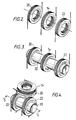
- FIG 2 is a perspective diagrammatic representation of the arrangement and interrelationship of the toroidal coils 14, 20 and 22, used in the embodiment of Figure 1.
- the coils 14, 20 and 22 are located in close proximity to one another and are air coupled. The actual physical location of the coils is to place them as close as possible, so that the full effects of magnetic flux produced in the coils 14 and 20 is combined and repoduced in the output coil 22.
- the three coils each were four inch coils, each having one hundred-ten (110) turns of number 22 enameled copper wire.
- Each of the coils 14, 20 and 22 of this embodiment has a DC resistance of 2.50 ohms. Coils of this size would not be used in a circuit designed for commecial transmitters, but this arrangement clealy demonstrated the effective operation of the system.
- the coils 14, 20 and 22 are selected to be correct for the frequency used as the carrier frequency.
- the audio frequency signal may be enhanced by the use of ferrite cores which reduce the necessity for high power.
- ferrite cores Such a configuration is shown in Figure 3 where a cylindrical ferrite core 32 is shown passing through the centers of the toroidal coils 14, 20 and 22. In all other respets the embodiment of Figure 3 is identical to the one of Figure 2.
- the use of ferrite cores, such as the core 32 reduces the power requirements of any system over the air coupled arrangement shown in Figure 2.
- the ferrite core functions effectively to multiply the effective flux from the carrier and the audio modulating signal to permit a reduction in size of any device for a given power level.
- the signal is placed on the carrier and detected by the core 22; and the resulting modulated signal then may be brought up to the desired power level by the linear amplifiers 25 and 26, such as is done with conventional SSB transmitters currently in use.
- the carrier is amplified by the amplifier 12 or cascaded amplifiers to the desired level.
- the audio power level then may be designed to produce a magnetic field through the use of ferrits or other suitable core materials to provide hundreds of times the gauss level of the coil itself. Since the flux density of the magnetic field which is produced by the currents flowing through the coils 14 and 20 is used as the modulating process, there is an advantage of significant flux multiplication by utilization of a suitable core material. Because the carrier and the modulating signals have been converted to magnetic flux, rather than either voltage or current, as is used in conventional modulator circuits, it becomes a matter of the degree of flux density rather than watts.
- a twenty-five watt audio signal can be multiplied to the same flux density as tow hundred (200) or three hundred (300) watts if only a coil without a ferite core were to be used. Consequently, the input of twenty-five (25) watts of audio power into a coil, which has a high permeability core through it, can produce an effective flux density which is equal to an excess of a two hundred (200) watt input. When this flux is placed in conjunction with the flux of the half-wave carrier signal, the effective output for the modulated carrier signal in this example is approximately three hundred (300) watts.
- Experiments using high permeability ferrite cores have illustrated that the actual value of the flux density (B) is greatly increased over an air core arrangement for any given current level.
- phase or FM modulation no longer is limited to taking power from the carrier and placing it into the sideband as with a conventional phase or FM signal.
- the result is an amplitude modulated, phase and frequency modulated carrier which takes power from the lower sideband and adds it to the generated harmonic sideband of the phase or frequency modulated signal.
- Power may be generated from the audio modulation signal and multiplied through the use of flux increases created by the high value ferrite material. The effective radiated power is the same, but the power input requirements for the system are decreased substantially.
- modulation is not limited to 100%. This is true because when unidirectional or uni-polar carrier is generated, there is no lower sideband created. This eliminates the equal and opposite effect of double sideband, which effect acts to cancel or reduce the power possible to the sidebands because one is positive going and the other is negative going in direction. Also, because the pulsating current in the carrier coil 14 is only unidirectional, without an opposite current flow, no opposite sideband can be created because the carrier in the coil 14 is at zero current during the opposite half of the generated carrier wave. A sideband cannot be generated if there is no band, (carrier), with which to do it.
- a transmitting station which currently, using conventional equipment, requires one hundred thousand (100,000) watts of power may produce the same effective transmitting range at a power level of sixty thousand (60,000) watts to seventy-five thousand (75,000) watts using the modulation system of Figure 1.
- many of the complex circuits now necessary for standard transmitting stations may be eliminated or reduced in complexity; so that the cost of the transmitting station also is reduced. Amplitude-phase modulation now may be accomplished directly, as explained above, without the high cost and complexity which present techniques require for such modulation.
- This multiplier generates frequencies in the range, for example, from 1 MHz to 105 MHz in a single step, but provides the frequencies at any of the various harmonics, already modulated both in frequency and phase, as well as amplitude.
- the filter 24, which is employed in the circuit of Figure 1 is selected to provide either pure frequency modulation, phase modulation, or amplitude modulation at the desired output carrier frequency for further amplification on up to the desired power level for transmission.
- the system requires only half as much of the band-width of normal or conventional AM/FM or phase modulation transmission systems.
- FIG. 4 Another variation of the coil arrangement shown in Figures 2 and 3 is illustrated in Figures 4, 5 and 6.
- the audio signal input coil 20 and the output coil 22 are shown wound on a common ferrite core 32, which is similar to the core 32 of the embodiment of Figure 3.
- the carrier coil 14, however, is not placed on the core 32, but instead the coil 14 is oriented at right angles to the axis of the cores 20 and 22, and is located on an axis perpendicular to the axis through the ferrite core 32.
- the coil 14 is attached to a flat ceramic permanent magnet plate 33, so that the flux changes produced by the current flowing through the carrier signal coil 14 result in corresponding variations in the magnetic field on the other face of the ceramic magnet plate 33.
- the flux coupling of the three coils 14, 20 and 22, results in an output signal from the coil 22 which is comparable to the one described above in conjunction with the embodiments of Figures 2 and 3 and also described in conjunction with the waveforms of Figure 7.
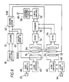
- Figure 8 illustrates a modification of the circuit of Figure 1 for use as an AM stereo or FM stereo transmitting system.
- the positive carrier, half-cycles for the right channel and the negative carrier half-cycles for the left channel as separate signals prior to amplification in the final power amplifier, the separate signals can be combined in the final stages to form a normal appearing, amplitude modulated signal, as far as the antenna 60 is concerned. Different information, however, is contained in the positive and negative portions of this signal. This is accomplished by the circuit of Figure 8.
- a single carrier oscillator 10 and an amplifier 12 are utilized, as in the embodiment of Figure 1.
- the output of the amplifier 12, however, is supplied to two different shaping circuits 42 and 63.
- the shaping circuit 42 supplies, for example, the positive half-cycles of the carrier oscillator signal, while the shaping circuit 63 provides the negative half-cycles of the carrier oscillator signal. If the output of these two circuits were recombined, a full sine wave carrier signal at the frequency of the oscillator 10 would result.
- the two halves of this signal are separately provided at the outputs of the shaping circuits 42 and 43.
- the output of the shaping circuit 42 is supplied to a carrier input coil 44.
- the audio input for the corresponding portion of the stereo input signal is supplied through a microphone 46, an audio input circuit 48, and audio amplifier 49 connected to the audio input modulator coil 50.
- An output coil 52 corresponding in operation to the output coil 22 of Figure 1, supplies output signals through a filter 54 connected to a combiner circuit 55.
- the output of the shaping circuit 63 is supplied to a circuit which is a duplicate of the one connected to the output of the shaping circuit 42.
- the carrier signals are supplied to a carrier toroidal coil 64, while the audio input signals for the other audio channel are supplied through a microphone 66, input circuit 68, and audio amplifier 69 to an input coil 70.
- An output coil 72 comparable to the output coil 22 of Figures 1 through 4, supplies the modulated signals for this channel to a filter 74.
- These signals are combined with the signals from the filter 54 in the combiner circuit 55 which then produces the full stereo signal to a conventional linear amplifier circuit 56.
- the circuit 56 amplifies the signal to the desired transmission level and supplies it through an antenna matching circuit 58 to a transmitting antenna 60.
- the signal which is transmitted is a normal appearing amplitude modulated signal (provided that amplitude modulation is selected by the filters 54 and 74).
- the system which is illustrated in Figure 8 also may be used to produce FM stereo signals. The same process of separate and independent upper and lower sidebands is employed. No changes are necessary whatsoever to the circuits which are connected to the inputs of the filters 54 and 74. These filters are selected to pass the desired modulated frequency signal on to the combiner 55.
- the positive unidirectional signal is selected by one channel and the negative unidirectional signal is selected by the other, utilizing conventional FM receiver techniques.
Landscapes
- Engineering & Computer Science (AREA)
- Power Engineering (AREA)
- Transmitters (AREA)
- Near-Field Transmission Systems (AREA)
Applications Claiming Priority (2)
| Application Number | Priority Date | Filing Date | Title |
|---|---|---|---|
| US341769 | 1989-04-21 | ||
| US07/341,769 US4902987A (en) | 1989-04-21 | 1989-04-21 | Inductive modulator system |
Publications (2)
| Publication Number | Publication Date |
|---|---|
| EP0394069A2 true EP0394069A2 (de) | 1990-10-24 |
| EP0394069A3 EP0394069A3 (de) | 1991-08-14 |
Family
ID=23338962
Family Applications (1)
| Application Number | Title | Priority Date | Filing Date |
|---|---|---|---|
| EP19900304297 Withdrawn EP0394069A3 (de) | 1989-04-21 | 1990-04-20 | Induktive Modulatoranordnung |
Country Status (2)
| Country | Link |
|---|---|
| US (1) | US4902987A (de) |
| EP (1) | EP0394069A3 (de) |
Families Citing this family (7)
| Publication number | Priority date | Publication date | Assignee | Title |
|---|---|---|---|---|
| US6047214A (en) * | 1998-06-09 | 2000-04-04 | North Carolina State University | System and method for powering, controlling, and communicating with multiple inductively-powered devices |
| US20050137652A1 (en) * | 2003-12-19 | 2005-06-23 | The Board of Regents of the University of Texas at Dallas | System and method for interfacing cellular matter with a machine |
| US20090198293A1 (en) * | 2003-12-19 | 2009-08-06 | Lawrence Cauller | Microtransponder Array for Implant |
| US7630771B2 (en) * | 2007-06-25 | 2009-12-08 | Microtransponder, Inc. | Grooved electrode and wireless microtransponder system |
| US9089707B2 (en) | 2008-07-02 | 2015-07-28 | The Board Of Regents, The University Of Texas System | Systems, methods and devices for paired plasticity |
| US8457757B2 (en) | 2007-11-26 | 2013-06-04 | Micro Transponder, Inc. | Implantable transponder systems and methods |
| WO2009070719A1 (en) * | 2007-11-26 | 2009-06-04 | Micro Transponder Inc. | Implanted driver with resistive charge balancing |
Family Cites Families (4)
| Publication number | Priority date | Publication date | Assignee | Title |
|---|---|---|---|---|
| DE464680C (de) * | 1928-08-24 | Erich F Huth G M B H Dr | Einrichtung zur Beeinflussung von elektrischen Schwingungen | |
| US2870416A (en) * | 1953-03-26 | 1959-01-20 | Honeywell Regulator Co | Magnetic modulator |
| US3040184A (en) * | 1958-07-01 | 1962-06-19 | Bell Telephone Labor Inc | Translation device having ferromagnetic core |
| US3172061A (en) * | 1961-08-24 | 1965-03-02 | Andrew B Malinowski | Low level magnetic modulator |
-
1989
- 1989-04-21 US US07/341,769 patent/US4902987A/en not_active Expired - Fee Related
-
1990
- 1990-04-20 EP EP19900304297 patent/EP0394069A3/de not_active Withdrawn
Also Published As
| Publication number | Publication date |
|---|---|
| EP0394069A3 (de) | 1991-08-14 |
| US4902987A (en) | 1990-02-20 |
Similar Documents
| Publication | Publication Date | Title |
|---|---|---|
| US1287982A (en) | Modulating system. | |
| Krauss et al. | Solid state radio engineering | |
| US2103090A (en) | Means for and method of generating electrical currents | |
| US1886616A (en) | Magnetic sound recording system | |
| US1778796A (en) | System and apparatus employing the hall effect | |
| US1825855A (en) | System and apparatus employing the "hall effect" | |
| US4902987A (en) | Inductive modulator system | |
| JP2019140442A (ja) | アンテナモジュールおよび伝送システム | |
| US1988006A (en) | Direction finding system | |
| US1558120A (en) | Radio receiving system | |
| US4686705A (en) | Special vestigial sideband signal for use in communication systems | |
| US2378581A (en) | Conversion of amplitude modulation to frequency modulation | |
| Smith et al. | Long-distance radio communication 100 years ago: The Alexanderson system at radio central [Historically Speaking] | |
| US3787772A (en) | F. m. transmitter employing magnetically modulated ferrimagnetic resonator | |
| US2159478A (en) | Magnetron system for simultaneous transmission and reception | |
| EP0172679A1 (de) | Frequenzmodulation- und Demodulation | |
| US4660222A (en) | Special vestigial sideband signal for use in communication systems | |
| US3007120A (en) | Modulation system | |
| US2227595A (en) | Modulator for high frequency oscillators | |
| US2539243A (en) | Radio modulation system | |
| CN223599845U (zh) | 信号传输系统与信号传输装置 | |
| US4050072A (en) | Signal combining apparatus | |
| US1578881A (en) | Polyphase-carrier-current broadcasting system and generator | |
| US3066259A (en) | Suppressed carrier transmitter | |
| US2894123A (en) | Radio transmitter with fixed tune amplifier stages |
Legal Events
| Date | Code | Title | Description |
|---|---|---|---|
| PUAI | Public reference made under article 153(3) epc to a published international application that has entered the european phase |
Free format text: ORIGINAL CODE: 0009012 |
|
| AK | Designated contracting states |
Kind code of ref document: A2 Designated state(s): DE ES FR GB IT NL |
|
| PUAL | Search report despatched |
Free format text: ORIGINAL CODE: 0009013 |
|
| AK | Designated contracting states |
Kind code of ref document: A3 Designated state(s): DE ES FR GB IT NL |
|
| STAA | Information on the status of an ep patent application or granted ep patent |
Free format text: STATUS: THE APPLICATION IS DEEMED TO BE WITHDRAWN |
|
| 18D | Application deemed to be withdrawn |
Effective date: 19920215 |