EP0393802B1 - Connection element pretreatment process for a gastight pipe connection - Google Patents
Connection element pretreatment process for a gastight pipe connection Download PDFInfo
- Publication number
- EP0393802B1 EP0393802B1 EP90250096A EP90250096A EP0393802B1 EP 0393802 B1 EP0393802 B1 EP 0393802B1 EP 90250096 A EP90250096 A EP 90250096A EP 90250096 A EP90250096 A EP 90250096A EP 0393802 B1 EP0393802 B1 EP 0393802B1
- Authority
- EP
- European Patent Office
- Prior art keywords
- oil
- connection
- test
- thread
- gas
- Prior art date
- Legal status (The legal status is an assumption and is not a legal conclusion. Google has not performed a legal analysis and makes no representation as to the accuracy of the status listed.)
- Revoked
Links
Images
Classifications
-
- F—MECHANICAL ENGINEERING; LIGHTING; HEATING; WEAPONS; BLASTING
- F16—ENGINEERING ELEMENTS AND UNITS; GENERAL MEASURES FOR PRODUCING AND MAINTAINING EFFECTIVE FUNCTIONING OF MACHINES OR INSTALLATIONS; THERMAL INSULATION IN GENERAL
- F16L—PIPES; JOINTS OR FITTINGS FOR PIPES; SUPPORTS FOR PIPES, CABLES OR PROTECTIVE TUBING; MEANS FOR THERMAL INSULATION IN GENERAL
- F16L15/00—Screw-threaded joints; Forms of screw-threads for such joints
- F16L15/001—Screw-threaded joints; Forms of screw-threads for such joints with conical threads
- F16L15/004—Screw-threaded joints; Forms of screw-threads for such joints with conical threads with axial sealings having at least one plastically deformable sealing surface
-
- E—FIXED CONSTRUCTIONS
- E21—EARTH DRILLING; MINING
- E21B—EARTH DRILLING, e.g. DEEP DRILLING; OBTAINING OIL, GAS, WATER, SOLUBLE OR MELTABLE MATERIALS OR A SLURRY OF MINERALS FROM WELLS
- E21B17/00—Drilling rods or pipes; Flexible drill strings; Kellies; Drill collars; Sucker rods; Cables; Casings; Tubings
- E21B17/02—Couplings; joints
- E21B17/08—Casing joints
-
- E—FIXED CONSTRUCTIONS
- E21—EARTH DRILLING; MINING
- E21B—EARTH DRILLING, e.g. DEEP DRILLING; OBTAINING OIL, GAS, WATER, SOLUBLE OR MELTABLE MATERIALS OR A SLURRY OF MINERALS FROM WELLS
- E21B47/00—Survey of boreholes or wells
- E21B47/10—Locating fluid leaks, intrusions or movements
- E21B47/117—Detecting leaks, e.g. from tubing, by pressure testing
-
- G—PHYSICS
- G01—MEASURING; TESTING
- G01M—TESTING STATIC OR DYNAMIC BALANCE OF MACHINES OR STRUCTURES; TESTING OF STRUCTURES OR APPARATUS, NOT OTHERWISE PROVIDED FOR
- G01M3/00—Investigating fluid-tightness of structures
- G01M3/02—Investigating fluid-tightness of structures by using fluid or vacuum
- G01M3/04—Investigating fluid-tightness of structures by using fluid or vacuum by detecting the presence of fluid at the leakage point
- G01M3/20—Investigating fluid-tightness of structures by using fluid or vacuum by detecting the presence of fluid at the leakage point using special tracer materials, e.g. dye, fluorescent material, radioactive material
- G01M3/22—Investigating fluid-tightness of structures by using fluid or vacuum by detecting the presence of fluid at the leakage point using special tracer materials, e.g. dye, fluorescent material, radioactive material for pipes, cables or tubes; for pipe joints or seals; for valves; for welds; for containers, e.g. radiators
- G01M3/223—Investigating fluid-tightness of structures by using fluid or vacuum by detecting the presence of fluid at the leakage point using special tracer materials, e.g. dye, fluorescent material, radioactive material for pipes, cables or tubes; for pipe joints or seals; for valves; for welds; for containers, e.g. radiators for pipe joints or seals
Definitions
- the invention relates to a method for pretreating the connecting elements of a gas-tight pipe connection according to the preamble of the main claim.
- the pipe connection of a string consisting of screwed threaded pipes for use in the oil and gas industry has the task on the one hand of absorbing the string load and on the other hand ensuring the tightness of the connection.
- the threaded section of the pipe ends and the socket has e.g. a conical API thread with a corresponding overlap. Due to the thread overlap, high surface pressures arise when screwing.
- surface coatings and greases were developed, which enable screwing without fretting.
- These thread greases are lubricious pastes with a high proportion of finely divided solid particles, e.g. Graphite, metals or Teflon. In addition to easy screwing, these greases support the hydraulic tightness of the connection. (Petroleum, Erdpas 1983, 5.293-296).
- the tightness of the connection is achieved by a cover in the metallic sealing seat.
- the butt shoulders serve as screw-in limiters and ensure that the metallic sealing seat remains activated with increasing strand load.
- the conical thread therefore does not have to perform a sealing function and, in contrast to the API thread, its task is only to transfer the strand load.
- GB-A-21 04 919 discloses a pipe connection with a metallic sealing seat and a special surface coating. Both the sleeve element and the pipes made of high-chromium steel (> 10% Cr) to be connected to one another are provided with a coating consisting of two layers at least in the sealing seat area after degreasing.
- a metal or an alloy from the group Fe, Ni, Zn, Co, Cu, Mn or Cr is first applied by means of a wet electrolysis and then an electrolytically deposited layer of a metal or alloy from the group Fe, Cu, Zn, Cr or Ni placed. This surface treatment is intended to prevent seizure even with multiple screw connections. The tightness of the connection was checked according to the API specification (RP-37). The lubricant used in the multiple screw connection is not disclosed
- a first suggestion is to vary the amount of API thread grease applied, ie to apply very thin layers of grease.
- This proposal has failed because of the problem of the reproducibility of the application of the thin layer of fat since it is local Falling below the minimum fat layer led to feeding.
- Another proposal is aimed at reducing the viscosity of the thread grease by adding solvents. It turned out that the solvents do not evaporate as quickly as hoped, and if the dilution is too great, the grease runs down from the area of the thread end and there is feeding.
- the sleeve is treated with Molywell, a screwing substance with only a small proportion of solvents.
- the thread area is additionally sprayed with Teflon.
- a disadvantage of this proposal is the higher coefficient of friction in the threads caused by the Molywell, so that only a reduced proportion of the total screwing torque remains for the activation of the sealing seat by the butt shoulders.
- the possibility of allowing a higher tightening torque means that it is necessary to determine a correction factor that is cumbersome to determine for all types of loads and threads.
- the above proposal is quite complex, since the pre-treatment before the screwing requires the use of a specialist company.
- the object of the invention is to provide an improved method for pretreating the connecting elements of a gas-tight pipe connection with a metallic sealing seat and butt shoulder, on the one hand is inexpensive and allows easy handling when screwing and with which seizure is prevented even with multiple screwing and the tightness of the screwed connection can be reproducibly and meaningfully checked in a shorter time than before.
- the method according to the invention is characterized in that the pretreatment of the connecting elements is simple and inexpensive. So far, it has been common to coat both the connecting element designed as a sleeve and the pin with a zinc-phosphate layer in order to meet the requirements of API RP 37 with regard to multiple screw connections. According to the new proposal, only the sleeve is pre-treated and the spigot part remains bare. The resulting cost advantage is immediately obvious.
- the proposed coating preferably consists of a manganese-phosphate layer which is chemically deposited on the surface of the sleeve by means of a combination of different baths.
- the crystal structure of the manganese phosphate layer is very hard and has a fine grain in comparison to the zinc phosphate layer that has been customary to date. In conjunction with a strong bond to the metal surface and a compact structure, this layer is very resistant to combined loads such as surface pressure and shear force.
- the layer built up is very uniform in thickness and wear-resistant with regard to multiple screw connections.
- the sleeve can also be coated with electrolytically deposited tin or copper.
- electrolytically deposited tin or copper are particularly useful for high-alloy materials such as. B. ferritic, ferritic-austenitic and austenitic steels. Because of the tendency of the elements chromium and nickel to passivate, no manganese-phosphate layer can be built up in these steels.
- Another advantage of the method according to the invention can be seen in the fact that an oil is used as a lubricant instead of the thread grease previously used for screwing. Applying the oil to the sealing seat and the threaded area of the spigot and socket element by brushing or spraying is extremely easy and does not require any special knowledge of the drilling team.
- the viscosity of the oil is in a range of ⁇ 350 mm2 / sec at 40 degrees Celsius, preferably about 220 mm2 / sec at 40 degrees Celsius or 20 mm2 / sec at 100 degrees Celsius. This viscosity is sufficient so that the oil does not run down in extreme temperature conditions in hot climates and that there may be seizures at the end of the thread.
- test holding time can be at least halved, so that the cycle time on the drilling rig is reduced accordingly.
- the additional testing effort is only meaningful and justifiable if the test result can be obtained in a short time, so that the cycle time on the drilling rig is not unnecessarily extended and the result is reproducibly meaningful and no pseudo-leaks are simulated.
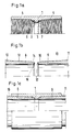
- the pretreated sleeve 1 is shown in a partial longitudinal section. After the chemical pretreatment, not shown here, the sealing seat area 6, 7, both butt shoulders 2, 3 and both threaded sections 4, 5 are covered with a manganese-phosphate layer.
- Each pin element 8.9 has a threaded section 12.13, a sealing seat surface 14.15 and a butt shoulder 16.17. Before screwing, both the sleeve 1 and the pin 8.9 are completely cleaned and then old connecting elements are brushed or sprayed with oil.
- 1c shows the pipe connection in the screwed state, the sealing surfaces 14, 15 of the pin elements 8.9 together with the sealing surfaces 6.7 of the sleeve 1 forming a metallic sealing seat.
- the threaded sections 4,5,12,13 are complementary conical to each other.
- the selected thread type for the threaded sections 4, 5, 12, 13 is of minor importance for the method according to the invention.
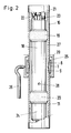
- FIG 2 the arrangement for the gas tightness test is shown in a longitudinal section.
- a test mandrel 18 with two packer elements 19, 20 arranged at a distance from one another is inserted through the pipe 10 screwed into the sleeve 1.
- the test mandrel 18 is connected at its upper end to a holding rod 21 and a hydraulic line 22 for setting the packer elements 19, 20 and a test gas line 23.
- a guide 24 made of hard rubber.
- a split jacket pipe 25 is placed, which has a connecting line 26, which with the detector, not shown here, for. B. a gas chromatograph is connected. So that the supplied test gas can flow into the annular space 27, which is formed by the remaining volume of the test mandrel 18 and the bore of the tubes 10, 11, the test mandrel 18 has at least one or more openings 28.
- test method now runs in such a way that the annular space 27 is pressurized by means of the test gas supplied, for. B. with 125 bar, the hydraulically inflated packer elements 19, 20 provide the necessary seal up and down. If the pipe connection in the area of the metallic sealing seat is leaky, the test gas would flow through the threaded sections 4, 5, 12, 13 screwed together (see FIGS. 1a + 1b) and into the annular space formed by the jacket pipe 25 and the outer surface of the pipe connection 29 arrive. From there it would be fed via line 26 to the detector, which would then trigger a corresponding display.
Description
Die Erfindung betrifft ein Verfahren zur Vorbehandlung der Verbindungselemente einer gasdichten Rohrverbindung gemäß dem Gattungsbegriff des Hauptanspruches.The invention relates to a method for pretreating the connecting elements of a gas-tight pipe connection according to the preamble of the main claim.
Die Rohrverbindung eines aus miteinander verschraubbaren Gewinderohren bestehenden Stranges für den Einsatz in der Erdöl- und Erdgasindustrie hat zum einen die Aufgabe die Stranglast aufzunehmen und zum anderen die Dichtheit der Verbindung zu sichern. Zur Erfüllung dieser Aufgaben weist der Gewindeabschnitt der Rohrenden und der Muffe z.B. ein konisches API-Gewinde mit einer entsprechenden Uberdeckung auf. Bedingt durch die Gewindeüberdeckung entstehen beim Verschrauben hohe Oberflächenpressungen. Zur Beherrschung dieser großen Belastung wurden Oberflächenbeschichtungen und Fette entwickelt, die ein Verschrauben ohne Fressen ermöglicht. Diese Gewindefette sind schmierfähige Pasten mit einem hohen Anteil an feinverteilten Feststoffpartikeln, wie z.B. Graphit, Metalle oder Teflon. Außer einem problemlosen Verschrauben unterstützen diese Fette die hydraulische Dichtheit der Verbindung. (Erdöl, Erdpas 1983, 5. 293-296).The pipe connection of a string consisting of screwed threaded pipes for use in the oil and gas industry has the task on the one hand of absorbing the string load and on the other hand ensuring the tightness of the connection. To accomplish these tasks, the threaded section of the pipe ends and the socket has e.g. a conical API thread with a corresponding overlap. Due to the thread overlap, high surface pressures arise when screwing. To master this high load, surface coatings and greases were developed, which enable screwing without fretting. These thread greases are lubricious pastes with a high proportion of finely divided solid particles, e.g. Graphite, metals or Teflon. In addition to easy screwing, these greases support the hydraulic tightness of the connection. (Petroleum, Erdpas 1983, 5.293-296).
Bei der von verschiedenen Herstellern entwickelten gasdichten Verbindung wird die Dichtheit der Verbindung durch eine Uberdeckung im metallischen Dichtsitz erzielt. Die Stoßschultern dienen als Einschraubbegrenzung und sie sorgen dafür, daß mit steigender Stranglast der metallische Dichtsitz aktiviert bleibt. Das konische Gewinde braucht demzufolge keine Dichtfunktion zu übernehmen und seine Aufgabe besteht im Gegensatz zum API-Gewinde nur in der Übertragung der Stranglast.In the gas-tight connection developed by various manufacturers, the tightness of the connection is achieved by a cover in the metallic sealing seat. The butt shoulders serve as screw-in limiters and ensure that the metallic sealing seat remains activated with increasing strand load. The conical thread therefore does not have to perform a sealing function and, in contrast to the API thread, its task is only to transfer the strand load.
In der GB-A-21 04 919 ist eine Rohrverbindung mit einem metallischen Dichtsitz und einer speziellen Oberflächenbeschichtung offenbart. Sowohl das Muffenelement als auch die miteinander zu verbindenden Rohre aus einem hochchromhaltigen Stahl (> 10 % Cr) werden mindestens im Dichtsitzbereich nach dem Entfetten mit einem aus zwei Schichten bestehenden Überzug versehen. Dazu wird zuerst mittels einer Naßelektrolyse ein Metall oder eine Legierung aus der Gruppe Fe, Ni, Zn, Co, Cu, Mn oder Cr aufgebracht und darüber eine elektrolytisch abgeschiedene Schicht eines Metalls oder Legierung aus der Gruppe Fe, Cu, Zn, Cr oder Ni gelegt. Durch diese Oberflächenbehandlung soll ein Fressen auch bei Mehrfachverschraubung verhindert werden. Die Dichtheit der Verbindung wurde entsprechend der API-Spezifikation (RP-37) überprüft. Das bei der Mehrfachverschraubung verwendete Schmiermittel ist nicht offenbartGB-A-21 04 919 discloses a pipe connection with a metallic sealing seat and a special surface coating. Both the sleeve element and the pipes made of high-chromium steel (> 10% Cr) to be connected to one another are provided with a coating consisting of two layers at least in the sealing seat area after degreasing. For this purpose, a metal or an alloy from the group Fe, Ni, Zn, Co, Cu, Mn or Cr is first applied by means of a wet electrolysis and then an electrolytically deposited layer of a metal or alloy from the group Fe, Cu, Zn, Cr or Ni placed. This surface treatment is intended to prevent seizure even with multiple screw connections. The tightness of the connection was checked according to the API specification (RP-37). The lubricant used in the multiple screw connection is not disclosed
Um gasdichte Verbindungen im Gewinde- und Dichtsitzbereich zuverlässig verschrauben zu können, werden auch bei diesen Rohrverbindungen bislang Oberflächenbeschichtungen und Feststoffschmierpasten verwendet, um Fresserscheinungen auszuschalten und Mehrfachverschraubungen zu ermöglichen. Der große Nachteil bei Verwendung von Feststoffschmierpasten bzw. Verschraubfetten bei gasdichten Verbindungen mit konischen Gewindeabschnitten ist, daß sie im Gewindebereich eine hohe temporäre Dichtwirkung erzeugen. Wird eine gasdichte Verbindung nach dem Verschrauben auf Dichtheit getestet, so gibt das Testergebnis aufgrund der temporären Dichtheit des Gewindes keine gesicherte Aussage über die Dichtheit des Systems, obwohl die eingesetzten Meßverfahren in der Lage sind, Leckageraten von weniger als 1 Liter pro Jahr zu detektieren und die Testdrücke im Bereich der Mindest-Innendruckfestigkeit der Verbindungen liegen. Die beim Einbau im Feld zur Verfügung stehende Prüfzeit (1 - 3 Minuten) reicht bei weitem nicht aus, die durch das Verschraubfett erzeugte temporäre Dichtung sicher zu überwinden. Wie entsprechende Versuche gezeigt haben, wird deshalb bei Verwendung von Gewindefetten sehr oft eine Gasdichtheit nur vorgetäuscht. Die Versuche haben weiterhin gezeigt, daß mit steigendem Rohrdurchmesser aufgrund des größeren Gewindewiderstandes bedingt durch Durchmesser und Gewindelänge die Pseudodichtheit zunimmt.In order to be able to reliably screw gas-tight connections in the threaded and sealing seat area, surface coatings and solid lubricating pastes have also been used in these pipe connections to prevent seizures and enable multiple screw connections. The major disadvantage when using solid lubricating pastes or screw greases for gas-tight connections with conical thread sections is that they produce a high temporary sealing effect in the thread area. If a gas-tight connection is tested for tightness after screwing, the test result does not provide any reliable information about the tightness of the system due to the temporary tightness of the thread, although the measuring methods used are able to detect leakage rates of less than 1 liter per year and the test pressures are in the range of the minimum internal compressive strength of the connections. The test time available for installation in the field (1 - 3 minutes) is far from sufficient to safely overcome the temporary seal created by the screw grease. As appropriate tests have shown, gas tightness is very often only simulated when using threaded greases. The experiments have further shown that with increasing pipe diameter due to the greater thread resistance due to diameter and thread length, the pseudo-tightness increases.
In der Vergangenheit sind nun eine Vielzahl von Vorschlägen unterbreitet worden, um dieses Problem zu überwinden.A variety of proposals have now been made in the past to overcome this problem.
Ein erster Vorschlag geht dahin, die Menge des aufgetragenen API-Gewindefettes zu variieren, d. h. sehr dünne Fettschichten aufzutragen. Dieser Vorschlag ist am Problem der Reproduzierbarkeit des Auftragens der dünnen Fettmengenschicht gescheitert, da örtliche Unterschreitungen der Mindestfettschicht zu Fresserscheinung führten. Ein weiterer Vorschlag zielt in Richtung der Erniedrigung der Viskosität des Gewindefettes durch Beimischung von Lösungsmitteln. Dabei stellte sich heraus, daß die Lösungsmittel nicht so schnell, wie erhofft, verdampfen und bei zu großer Verdünnung das Fett vom Bereich des Gewindeendes herunterläuft und es dort zu Fresserscheinungen kommt.A first suggestion is to vary the amount of API thread grease applied, ie to apply very thin layers of grease. This proposal has failed because of the problem of the reproducibility of the application of the thin layer of fat since it is local Falling below the minimum fat layer led to feeding. Another proposal is aimed at reducing the viscosity of the thread grease by adding solvents. It turned out that the solvents do not evaporate as quickly as hoped, and if the dilution is too great, the grease runs down from the area of the thread end and there is feeding.
Bei einem weiteren Vorschlag wird die Muffe mit Molywell, einer Verschraubsubstanz mit nur einem geringen Anteil an Lösungsmitteln behandelt. Unmittelbar vor der Verschraubung wird der Gewindebereich zusätzlich mit Teflon besprüht. Nachteilig bei diesem Vorschlag ist der durch das Molywell bedingte höhere Reibwert in den Gewindegängen, so daß vom Gesamtverschraubmoment nur ein reduzierter Anteil für die Aktivierung des Dichtsitzes durch die Stoßschultern verbleibt. Die Möglichkeit, ein höheres Verschraubmoment zuzulassen, bedeutet die Notwendigkeit der Ermittlung eines Korrekturfaktors, der für alle Belastungsarten und Gewindearten umständlich zu ermitteln ist. Außerdem ist der genannte Vorschlag recht aufwendig, da die Vorbehandlung vor der Verschraubung die Inanspruchnahme einer Spezialfirma erforderlich macht.In another proposal, the sleeve is treated with Molywell, a screwing substance with only a small proportion of solvents. Immediately before screwing, the thread area is additionally sprayed with Teflon. A disadvantage of this proposal is the higher coefficient of friction in the threads caused by the Molywell, so that only a reduced proportion of the total screwing torque remains for the activation of the sealing seat by the butt shoulders. The possibility of allowing a higher tightening torque means that it is necessary to determine a correction factor that is cumbersome to determine for all types of loads and threads. In addition, the above proposal is quite complex, since the pre-treatment before the screwing requires the use of a specialist company.
Ein weiterer sehr aufwendiger Vorschlag betrifft das Ionenimplantieren. Bei diesem Verfahren dringen ionisierte Metalle, z. B. Palladium, Silber, Chrom, Gold in die Muffenoberfläche. Diese teure Vorbehandlung ist nur in einer Spezialfirma möglich und bedeutet für den Verwender eine aufwendige Logistik und eine Abhängigkeit möglicherweise von nur einem Lieferanten.Another very complex proposal concerns ion implantation. In this process ionized metals, e.g. B. Palladium, silver, chrome, gold in the sleeve surface. This expensive pretreatment is only possible in a specialist company and means a complex logistical process for the user and possibly a dependency on only one supplier.
Aufgabe der Erfindung ist es, ein verbessertes Verfahren zur Vorbehandlung der Verbindungselemente einer gasdichten Rohrverbindung mit metallischem Dichtsitz und Stoßschulter anzugeben, das zum einen kostengünstig ist und eine einfache Handhabung beim Verschrauben gestattet und mit dem ein Fressen auch bei Mehrfachverschraubung verhindert wird und die Dichtheit der verschraubten Verbindung reproduzierbar und aussagefähig in kürzerer Zeit als bisher überprüft werden kann.The object of the invention is to provide an improved method for pretreating the connecting elements of a gas-tight pipe connection with a metallic sealing seat and butt shoulder, on the one hand is inexpensive and allows easy handling when screwing and with which seizure is prevented even with multiple screwing and the tightness of the screwed connection can be reproducibly and meaningfully checked in a shorter time than before.
Diese Aufgabe wird durch die kennzeichnenden Merkmale des Hauptanspruches gelöst. Vorteilhafte Weiterbildungen sind in den Unteransprüchen festgelegt.This object is achieved by the characterizing features of the main claim. Advantageous further developments are defined in the subclaims.
Das erfindungsgemäße Verfahren zeichnet sich dadurch aus, daß die Vorbehandlung der Verbindungselemente einfach und kostengünstig ist. Bisher war es üblich, sowohl das als Muffe ausgebildete Verbindungselement als auch den Zapfen mit einer Zink-Phosphatschicht zu überziehen, um die Anforderungen der API RP 37 im Hinblick auf Mehrfachverschraubungen zu erfüllen. Entsprechend dem neuen Vorschlag wird nur die Muffe vorbehandelt und der Zapfenteil bleibt blank. Der sich daraus ergebende Kostenvorteil liegt unmittelbar auf der Hand. Der vorgeschlagene Überzug besteht vorzugsweise aus einer Mangan-Phosphatschicht, die mittels einer Kombination verschiedener Bäder chemisch auf der Oberfläche der Muffe abgeschieden wird. Im Vergleich zur bisher üblichen Zink-Phosphatschicht ist die Kristallstruktur der Mangan-Phosphatschicht sehr hart und weist ein feines Korn auf. In Verbindung mit einer starken Bindungshaftung mit der Metalloberfläche und einer Kompaktstruktur ist diese Schicht sehr widerstandsfähig gegen kombinierte Belastung wie Flächenpressung und Scherkraft. Außerdem ist die aufgebaute Schicht sehr gleichmässig in der Dicke und verschleißfest im Hinblick auf Mehrfachverschraubungen.The method according to the invention is characterized in that the pretreatment of the connecting elements is simple and inexpensive. So far, it has been common to coat both the connecting element designed as a sleeve and the pin with a zinc-phosphate layer in order to meet the requirements of API RP 37 with regard to multiple screw connections. According to the new proposal, only the sleeve is pre-treated and the spigot part remains bare. The resulting cost advantage is immediately obvious. The proposed coating preferably consists of a manganese-phosphate layer which is chemically deposited on the surface of the sleeve by means of a combination of different baths. The crystal structure of the manganese phosphate layer is very hard and has a fine grain in comparison to the zinc phosphate layer that has been customary to date. In conjunction with a strong bond to the metal surface and a compact structure, this layer is very resistant to combined loads such as surface pressure and shear force. In addition, the layer built up is very uniform in thickness and wear-resistant with regard to multiple screw connections.
Alternativ zur Mangan-Phosphatschicht kann die Muffe auch mit elektrolytisch abgeschiedenen Zinn oder Kupfer überzogen werden. Diese Alternative, mit denen vergleichbare Mehrfachverschraubungen ohne Freßerscheinungen erzielbar sind, bietet sich vor allen Dingen für hochlegierte Werkstoffe, wie z. B. ferritische, ferritisch-austenitische und austenitische Stähle an. Bei diesen Stählen kann wegen der Passivierungsneigung der Elemente Chrom und Nickel keine Mangan-Phosphatschicht aufgebaut werden.As an alternative to the manganese-phosphate layer, the sleeve can also be coated with electrolytically deposited tin or copper. These An alternative, with which comparable multiple screw connections can be achieved without seizing, is particularly useful for high-alloy materials such as. B. ferritic, ferritic-austenitic and austenitic steels. Because of the tendency of the elements chromium and nickel to passivate, no manganese-phosphate layer can be built up in these steels.
Ein weiterer Vorteil des erfindungsgemäßen Verfahrens ist darin zu sehen, daß statt des bisher üblichen Gewindefettes zum Verschrauben ein Öl als Schmiermittel verwendet wird. Das Auftragen des Öles auf dem Dichtsitz und Gewindebereich von Zapfen- und Muffenelement durch Pinseln oder Sprühen ist denkbar einfach und erfordert keine Spezialkenntnisse der Bohrmannschaft und es sind zusätzlich keine teuren Spezialmittel wie z. B. Teflon erforderlich. Die Viskosität des Öles liegt in einem Bereich von < 350 mm²/sec bei 40 Grad Celsius, vorzugsweise bei etwa 220 mm²/sec bei 40 Grad Celsius bzw. 20 mm²/sec bei 100 Grad Celsius. Diese Viskosität ist ausreichend, damit bei extremen Temperaturverhältnissen in heißen Klimazonen das Öl nicht herabläuft und damit Freßerscheinungen am Gewindeende auftreten können. Die Verwendung eines Öles führt nicht zu einer temporären Dichtwirkung im Gewinde, so daß das Prüfgas, das bei dem Gasdichtheitstest verwendet wird, in kurzer Zeit die Gewindegänge durchströmt und detektiert wird, falls der metallische Dichtsitz undicht sein sollte. Da die Detektierung kurzzeitig und reproduzierbar erfolgt, ist die volle Ausschöpfung der bisher üblichen Prüfhaltezeit von 3 min. nicht erforderlich. Mit der erfindungsgemäßen Vorbehandlung kann die Prüfhaltezeit zumindestens halbiert werden, so daß die Taktzeit auf dem Bohrturm sich entsprechend reduziert. Mit zunehmender Bohrtiefe nimmt die Bedeutung des vorher durchgeführten Gasdichtheitstestes zu, da der Aufwand und die Kosten extrem ansteigen, falls aus einer Tiefe von 3000 und mehr der Strang wegen Undichtheit einer am Anfang liegenden Verbindung wieder hochgehoben werden muß. Der zusätzliche Prüfaufwand ist aber nur dann sinnvoll und zu vertreten, wenn das Prüfergebnis in kurzer Zeit zu erhalten ist, so daß die Taktzeit auf dem Bohrturm nicht unnötig verlängert wird und das Ergebnis reproduzierbar aussagefähig ist und keine Pseudodichtheiten vorgetäuscht werden.Another advantage of the method according to the invention can be seen in the fact that an oil is used as a lubricant instead of the thread grease previously used for screwing. Applying the oil to the sealing seat and the threaded area of the spigot and socket element by brushing or spraying is extremely easy and does not require any special knowledge of the drilling team. B. Teflon required. The viscosity of the oil is in a range of <350 mm² / sec at 40 degrees Celsius, preferably about 220 mm² / sec at 40 degrees Celsius or 20 mm² / sec at 100 degrees Celsius. This viscosity is sufficient so that the oil does not run down in extreme temperature conditions in hot climates and that there may be seizures at the end of the thread. The use of an oil does not lead to a temporary sealing effect in the thread, so that the test gas that is used in the gas tightness test flows through the threads in a short time and is detected if the metallic sealing seat should leak. Since the detection is short-term and reproducible, the test hold time of 3 minutes, which has been the norm up to now, is fully utilized. not mandatory. With the pretreatment according to the invention, the test holding time can be at least halved, so that the cycle time on the drilling rig is reduced accordingly. With increasing drilling depth, the importance of the previously carried out gas tightness test increases, since the effort and the costs increase extremely, if from a depth of 3000 or more the strand again due to leakage of an initial connection must be lifted up. However, the additional testing effort is only meaningful and justifiable if the test result can be obtained in a short time, so that the cycle time on the drilling rig is not unnecessarily extended and the result is reproducibly meaningful and no pseudo-leaks are simulated.
Anhand der Zeichnung wird das erfindungsgemäße Verfahren näher erläutert. Es zeigen:
- Figur 1a
- einen Teillängsschnitt durch eine vorbehandelte Muffe
- Figur 1b
- einen Teillängsschnitt der unbehandelten Zapfen
- Figur 1c
- einen Teillängsschnitt sowie eine Ansicht der Rohrverbindung im verschraubten Zustand
Figur 2- einen Längsschnitt durch die Anordnung für den Gasdichtheitstest
- Figure 1a
- a partial longitudinal section through a pretreated sleeve
- Figure 1b
- a partial longitudinal section of the untreated cones
- Figure 1c
- a partial longitudinal section and a view of the pipe connection in the screwed state
- Figure 2
- a longitudinal section through the arrangement for the gas tightness test
In Figur 1a ist in einem Teillängsschnitt die vorbehandelte Muffe 1 dargestellt. Nach der hier nicht gezeigten chemischen Vorbehandlung sind der Dichtsitzbereich 6,7, beide Stoßschultern 2,3 sowie beide Gewindeabschnitte 4,5 mit einer Mangan-Phosphatschicht überzogen. Die als Zapfen 8,9 ausgebildeten Verbindungselemente der beiden zu verschraubenden Rohre 10,11 bleiben unbehandelt blank (Figur 1b). Jedes Zapfenelement 8,9 weist einen Gewindeabschnitt 12,13, eine Dichtsitzfläche 14,15 und eine Stoßschulter 16,17 auf. Vor dem Verschrauben werden sowohl die Muffe 1 als auch die Zapfen 8,9 vollständig gereinigt und anschließend alte Verbindungselemente mit Öl eingepinselt bzw. eingesprüht. Figur 1c zeigt die Rohrverbindung im verschraubten Zustand, wobei die Dichtflächen 14,15 der Zapfenelemente 8,9 zusammen mit den Dichtflächen 6,7 der Muffe 1 einen metallischen Dichtsitz bilden. Die Gewindeabschnitte 4,5,12,13 sind komplementär konisch zueinander ausgebildet.In Figure 1a, the
Der gewählte Gewindetyp für die Gewindeabschnitte 4,5,12,13 ist für das erfindungsgemäße Verfahren von untergeordneter Bedeutung.The selected thread type for the threaded
In Figur 2 ist in einem Längsschnitt die Anordnung für den Gasdichtheitstest dargestellt. Nach dem Verschrauben wird durch das in der Muffe 1 eingeschraubte Rohr 10 ein Prüfdorn 18 mit zwei im Abstand voneinander angeordneten Packerelementen 19,20 eingeführt. Der Prüfdorn 18 ist an seinem oberen Ende mit einer Haltestange 21 und einer Hydraulikleitung 22 für das Setzen der Packerelemente 19,20 und einer Prüfgasleitung 23 verbunden. Am unteren Ende des Prüfdornes 18 befindet sich eine Führung 24 aus Hartgummi. Um die Rohrverbindung wird ein geteiltes Mantelrohr 25 gelegt, das eine Anschlußleitung 26 aufweist, die mit dem hier nicht dargestellten Detektor, z. B. ein Gaschromatographen verbunden ist. Damit das zugeführte Prüfgas in den Ringraum 27, der gebildet wird durch das Restvolumen von Prüfdorn 18 und Bohrung der Rohre 10,11 einströmen kann, weist der Prüfdorn 18 mindestens eine oder mehrere Öffnungen 28 auf.In Figure 2, the arrangement for the gas tightness test is shown in a longitudinal section. After screwing, a
Das Prüfverfahren läuft nun in der Weise ab, daß der Ringraum 27 mittels des zugeführten Prüfgases unter Druck gesetzt wird, z. B. mit 125 bar, wobei die hydraulisch aufgeblasenen Packerelemente 19,20 für die erforderliche Dichtung nach oben und nach unten sorgen. Sollte die Rohrverbindung im Bereich des metallischen Dichtsitzes undicht sein, so würde das Prüfgas durch die miteinander verschraubten Gewindeabschnitte 4,5,12,13 (siehe Figur 1a + 1b) strömen und in den durch das Mantelrohr 25 und der äußeren Oberfläche der Rohrverbindung gebildeten Ringraum 29 gelangen. Von dort würde es über die Leitung 26 dem Detektor zugeführt werden, der dann eine entsprechende Anzeige auslösen würde.The test method now runs in such a way that the
Claims (5)
- A method for the pretreatment of the steel connecting elements (1, 10, 11) of a gas-tight pipe connection with a metallic sealing seat (6, 7, 14, 15) and impact shoulders (2, 3, 16, 17) for the repeated screw-connecting of threaded pipes (10, 11) for the petroleum and natural gas industry in which the sealing region (6, 7, 14, 15) and threaded region (4, 5, 12, 13) of the connecting elements (1, 10, 11) is first surface-treated and before screw-connecting a lubricant is applied to the cleaned sealing region (6, 7, 14, 15) and threaded region (4, 5, 12, 13), characterised in that only the connecting element which is designed as a bushing (1) is provided on the inside with a coating and before screw-connecting oil is applied as a lubricant to the bushing (1) and to the connecting element designed as a plain journal (8, 9), the coating consisting of a manganese-phosphate layer in the case of connecting elements (1, 10, 11) made of carbon steel and the coating consisting of electrolytically, deposited tin or copper in the case of connecting elements (1, 10, 11) made of high-alloy steels.
- A method according to Claim 1, characterised in that the oil is an engine oil.
- A method according to Claim 1, characterised in that the oil is a slideway oil.
- A method according to Claims 1 to 3, characterised in that the oil is applied by brushes before screw-connecting .
- A method according to Claims 1 to 3, characterised in that the oil is sprayed on before screw-connecting.
Applications Claiming Priority (2)
| Application Number | Priority Date | Filing Date | Title |
|---|---|---|---|
| DE3913314 | 1989-04-19 | ||
| DE3913314A DE3913314C1 (en) | 1989-04-19 | 1989-04-19 |
Publications (3)
| Publication Number | Publication Date |
|---|---|
| EP0393802A2 EP0393802A2 (en) | 1990-10-24 |
| EP0393802A3 EP0393802A3 (en) | 1991-04-17 |
| EP0393802B1 true EP0393802B1 (en) | 1993-06-02 |
Family
ID=6379247
Family Applications (1)
| Application Number | Title | Priority Date | Filing Date |
|---|---|---|---|
| EP90250096A Revoked EP0393802B1 (en) | 1989-04-19 | 1990-04-11 | Connection element pretreatment process for a gastight pipe connection |
Country Status (6)
| Country | Link |
|---|---|
| US (1) | US5069761A (en) |
| EP (1) | EP0393802B1 (en) |
| JP (1) | JPH0361784A (en) |
| CA (1) | CA2014764A1 (en) |
| DE (2) | DE3913314C1 (en) |
| NO (1) | NO901705L (en) |
Families Citing this family (18)
| Publication number | Priority date | Publication date | Assignee | Title |
|---|---|---|---|---|
| EP0430383B1 (en) * | 1989-11-16 | 1993-11-03 | MANNESMANN Aktiengesellschaft | Process and apparatus for metallic coating of the threaded ends of connectable plastic pipes. |
| DE4120998C1 (en) * | 1991-06-21 | 1992-12-03 | Mannesmann Ag, 4000 Duesseldorf, De | |
| DE4121488A1 (en) * | 1991-06-26 | 1993-01-14 | Mannesmann Ag | METHOD FOR PRE-TREATING THE CONNECTING ELEMENTS OF A GAS-TIGHT SLEEVE PIPE CONNECTION |
| DE4219175C1 (en) * | 1992-06-09 | 1993-10-21 | Mannesmann Ag | Process for the pretreatment of the connecting elements of a gas-tight pipe connection |
| EP0786616B9 (en) * | 1994-10-04 | 2010-09-08 | NSCT Premium Tubulars B.V. | Steel pipe joint having high galling resistance and surface treatment method thereof |
| EP0968351B1 (en) * | 1997-03-21 | 2003-06-11 | Weatherford/Lamb, Inc. | Expandable slotted tubing string and method for connecting such a tubing string |
| GB9817246D0 (en) * | 1998-08-08 | 1998-10-07 | Petroline Wellsystems Ltd | Connector |
| AU6727100A (en) | 1999-08-27 | 2001-03-26 | Sumitomo Metal Industries Ltd. | Threaded joint for oil well pipe |
| ES2405841T3 (en) * | 2001-02-26 | 2013-06-04 | Nippon Steel & Sumitomo Metal Corporation | Surface treated steel product, its production method and chemical conversion treatment solution |
| JP3870732B2 (en) * | 2001-07-25 | 2007-01-24 | 住友金属工業株式会社 | Threaded joint for steel pipes with excellent seizure resistance |
| GB0130967D0 (en) * | 2001-12-24 | 2002-02-13 | Hunting Oilfield Services Ltd | Anti galling threaded joint |
| GB0215668D0 (en) * | 2002-07-06 | 2002-08-14 | Weatherford Lamb | Coupling tubulars |
| GB0221220D0 (en) * | 2002-09-13 | 2002-10-23 | Weatherford Lamb | Expanding coupling |
| GB0221585D0 (en) * | 2002-09-17 | 2002-10-23 | Weatherford Lamb | Tubing connection arrangement |
| GB0222321D0 (en) | 2002-09-25 | 2002-10-30 | Weatherford Lamb | Expandable connection |
| ITRM20020512A1 (en) * | 2002-10-10 | 2004-04-11 | Tenaris Connections Bv | THREADED PIPE WITH SURFACE TREATMENT. |
| US7887103B2 (en) | 2003-05-22 | 2011-02-15 | Watherford/Lamb, Inc. | Energizing seal for expandable connections |
| GB0311721D0 (en) | 2003-05-22 | 2003-06-25 | Weatherford Lamb | Tubing connector |
Family Cites Families (6)
| Publication number | Priority date | Publication date | Assignee | Title |
|---|---|---|---|---|
| JPS6057519B2 (en) * | 1981-08-20 | 1985-12-16 | 住友金属工業株式会社 | Oil country tubular joint with excellent seizure resistance and its manufacturing method |
| US4538840A (en) * | 1983-01-03 | 1985-09-03 | Delange Richard W | Connector means for use on oil and gas well tubing or the like |
| JPS60205091A (en) * | 1984-03-29 | 1985-10-16 | 住友金属工業株式会社 | Pipe joint for oil well pipe |
| US4758025A (en) * | 1985-06-18 | 1988-07-19 | Mobil Oil Corporation | Use of electroless metal coating to prevent galling of threaded tubular joints |
| DE3679196D1 (en) * | 1986-05-02 | 1991-06-13 | Sumitomo Metal Ind | CONNECTION FOR OILFIELD PIPES AND METHOD FOR THE PRODUCTION THEREOF. |
| US4692988A (en) * | 1986-08-19 | 1987-09-15 | Nowsco Well Service (U.K.) Limited | Screw thread protection |
-
1989
- 1989-04-19 DE DE3913314A patent/DE3913314C1/de not_active Expired - Fee Related
-
1990
- 1990-04-11 DE DE9090250096T patent/DE59001593D1/en not_active Revoked
- 1990-04-11 EP EP90250096A patent/EP0393802B1/en not_active Revoked
- 1990-04-13 JP JP2099135A patent/JPH0361784A/en active Pending
- 1990-04-16 US US07/509,735 patent/US5069761A/en not_active Expired - Fee Related
- 1990-04-18 CA CA002014764A patent/CA2014764A1/en not_active Abandoned
- 1990-04-18 NO NO90901705A patent/NO901705L/en unknown
Also Published As
| Publication number | Publication date |
|---|---|
| JPH0361784A (en) | 1991-03-18 |
| CA2014764A1 (en) | 1990-10-19 |
| DE59001593D1 (en) | 1993-07-08 |
| NO901705L (en) | 1990-10-22 |
| DE3913314C1 (en) | 1990-10-31 |
| NO901705D0 (en) | 1990-04-18 |
| EP0393802A2 (en) | 1990-10-24 |
| EP0393802A3 (en) | 1991-04-17 |
| US5069761A (en) | 1991-12-03 |
Similar Documents
| Publication | Publication Date | Title |
|---|---|---|
| EP0393802B1 (en) | Connection element pretreatment process for a gastight pipe connection | |
| DE69527635T3 (en) | STEEL TUBE CLUTCH WITH INCREASED ABRASION SAFETY AND METHOD FOR SURFACE TREATMENT | |
| EP0184978A2 (en) | Process for manufacturing pipes for the petroleum and natural gas industries and for drilling rods | |
| DE10103250A1 (en) | Common line for diesel engine | |
| DE2034185A1 (en) | Pipe element arrangement | |
| EP1384534A1 (en) | Apparatus for sectional autofrettage of tubes | |
| EP0520596B1 (en) | Connection element pretreatment process for a gastight sleeve-pipe coupling | |
| DE102007011617A1 (en) | Threaded bush fastening method, involves inserting bushes in boreholes, and screwing tool into threaded bushes by borehole device, where threaded bushes are closed on side to obtain pressure tight connection of boreholes | |
| EP1645346B1 (en) | Arrangement for the positive connection of two components | |
| DE4219175C1 (en) | Process for the pretreatment of the connecting elements of a gas-tight pipe connection | |
| DE10000796A1 (en) | Finishing process to consolidate the material of a curved/shaped pipe to carry a motor fuel feed at high pressure has external mechanical clamps to retain the pipe geometry while the interior is subjected to a high fluid pressure | |
| EP0080971B1 (en) | Process for the electrolytic deposition of tin on objects | |
| DE4120998C1 (en) | ||
| WO1991018187A1 (en) | Process for manufacturing a piston-cylinder unit and a piston-cylinder unit manufactured by said process | |
| DE2519875C2 (en) | The shaft has a welded stainless steel coating | |
| WO2006087072A1 (en) | Pivot pin for a ball joint and method for producing the same | |
| DE3125450A1 (en) | METHOD FOR HEAT TREATING METALS | |
| DE3716134C2 (en) | Process for reprocessing cylindrical components | |
| DD293176A5 (en) | VALVE SEAT RING FOR SHUTTER VALVES | |
| AT521614B1 (en) | Containers, especially pressure vessels | |
| DE3124613A1 (en) | Process for lining a pipeline with a flexible cylindrical film | |
| DE3938362C1 (en) | Applying metallic coating to FRP pipes - by spraying droplets at high velocity and adjustable impact angle | |
| DE102015201280A1 (en) | Flange seal with corrosion protection II | |
| EP3137237B1 (en) | Method for performing material tests for pipes made of steel, which pipes are to be treated with heat that influences the mechanical properties | |
| CH165232A (en) | Rifle. |
Legal Events
| Date | Code | Title | Description |
|---|---|---|---|
| PUAI | Public reference made under article 153(3) epc to a published international application that has entered the european phase |
Free format text: ORIGINAL CODE: 0009012 |
|
| AK | Designated contracting states |
Kind code of ref document: A2 Designated state(s): BE DE FR GB IT NL |
|
| PUAL | Search report despatched |
Free format text: ORIGINAL CODE: 0009013 |
|
| AK | Designated contracting states |
Kind code of ref document: A3 Designated state(s): BE DE FR GB IT NL |
|
| 17P | Request for examination filed |
Effective date: 19910319 |
|
| 17Q | First examination report despatched |
Effective date: 19911210 |
|
| GRAA | (expected) grant |
Free format text: ORIGINAL CODE: 0009210 |
|
| AK | Designated contracting states |
Kind code of ref document: B1 Designated state(s): BE DE FR GB IT NL |
|
| ITF | It: translation for a ep patent filed |
Owner name: BARZANO' E ZANARDO MILANO S.P.A. |
|
| ET | Fr: translation filed | ||
| REF | Corresponds to: |
Ref document number: 59001593 Country of ref document: DE Date of ref document: 19930708 |
|
| GBT | Gb: translation of ep patent filed (gb section 77(6)(a)/1977) |
Effective date: 19930901 |
|
| PLBI | Opposition filed |
Free format text: ORIGINAL CODE: 0009260 |
|
| PGFP | Annual fee paid to national office [announced via postgrant information from national office to epo] |
Ref country code: GB Payment date: 19940317 Year of fee payment: 5 |
|
| PLAB | Opposition data, opponent's data or that of the opponent's representative modified |
Free format text: ORIGINAL CODE: 0009299OPPO |
|
| PGFP | Annual fee paid to national office [announced via postgrant information from national office to epo] |
Ref country code: FR Payment date: 19940322 Year of fee payment: 5 |
|
| 26 | Opposition filed |
Opponent name: VALLOUREC INDUSTRIES Effective date: 19940225 |
|
| PG25 | Lapsed in a contracting state [announced via postgrant information from national office to epo] |
Ref country code: BE Effective date: 19940430 |
|
| R26 | Opposition filed (corrected) |
Opponent name: VALLOUREC INDUSTRIES Effective date: 19940225 |
|
| PGFP | Annual fee paid to national office [announced via postgrant information from national office to epo] |
Ref country code: DE Payment date: 19940526 Year of fee payment: 5 |
|
| NLR1 | Nl: opposition has been filed with the epo |
Opponent name: VALLOUREC INDUSTRIES |
|
| BERE | Be: lapsed |
Owner name: MANNESMANN A.G. Effective date: 19940430 |
|
| PG25 | Lapsed in a contracting state [announced via postgrant information from national office to epo] |
Ref country code: NL Effective date: 19941101 |
|
| NLV4 | Nl: lapsed or anulled due to non-payment of the annual fee | ||
| RDAG | Patent revoked |
Free format text: ORIGINAL CODE: 0009271 |
|
| STAA | Information on the status of an ep patent application or granted ep patent |
Free format text: STATUS: PATENT REVOKED |
|
| 27W | Patent revoked |
Effective date: 19950515 |
|
| GBPR | Gb: patent revoked under art. 102 of the ep convention designating the uk as contracting state |
Free format text: 950515 |