EP0392471B1 - Method for evaluating life of connection - Google Patents
Method for evaluating life of connection Download PDFInfo
- Publication number
- EP0392471B1 EP0392471B1 EP19900106875 EP90106875A EP0392471B1 EP 0392471 B1 EP0392471 B1 EP 0392471B1 EP 19900106875 EP19900106875 EP 19900106875 EP 90106875 A EP90106875 A EP 90106875A EP 0392471 B1 EP0392471 B1 EP 0392471B1
- Authority
- EP
- European Patent Office
- Prior art keywords
- connection
- life
- diagnosing
- crack
- solder
- Prior art date
- Legal status (The legal status is an assumption and is not a legal conclusion. Google has not performed a legal analysis and makes no representation as to the accuracy of the status listed.)
- Expired - Lifetime
Links
- 238000000034 method Methods 0.000 title claims description 45
- 229910000679 solder Inorganic materials 0.000 claims description 78
- 239000000758 substrate Substances 0.000 claims description 21
- 238000010008 shearing Methods 0.000 claims description 19
- 238000012545 processing Methods 0.000 claims description 13
- 239000004065 semiconductor Substances 0.000 claims description 12
- 238000004458 analytical method Methods 0.000 claims description 11
- 238000011156 evaluation Methods 0.000 claims description 11
- 238000004364 calculation method Methods 0.000 claims description 7
- 239000000463 material Substances 0.000 claims description 7
- 238000012937 correction Methods 0.000 claims description 2
- 230000015556 catabolic process Effects 0.000 description 6
- 238000012360 testing method Methods 0.000 description 6
- 238000007796 conventional method Methods 0.000 description 4
- 230000000875 corresponding effect Effects 0.000 description 4
- 230000007613 environmental effect Effects 0.000 description 3
- 241000058295 Camponotus propinquus Species 0.000 description 2
- 238000013461 design Methods 0.000 description 2
- 238000002844 melting Methods 0.000 description 2
- 230000008018 melting Effects 0.000 description 2
- 239000002184 metal Substances 0.000 description 2
- 229910052751 metal Inorganic materials 0.000 description 2
- 238000005476 soldering Methods 0.000 description 2
- 239000007787 solid Substances 0.000 description 2
- 101100129500 Caenorhabditis elegans max-2 gene Proteins 0.000 description 1
- 229910020220 Pb—Sn Inorganic materials 0.000 description 1
- 230000004913 activation Effects 0.000 description 1
- 230000002596 correlated effect Effects 0.000 description 1
- 230000007547 defect Effects 0.000 description 1
- 230000001419 dependent effect Effects 0.000 description 1
- 238000006073 displacement reaction Methods 0.000 description 1
- 230000000694 effects Effects 0.000 description 1
- 238000005516 engineering process Methods 0.000 description 1
- 238000012854 evaluation process Methods 0.000 description 1
- 230000020169 heat generation Effects 0.000 description 1
- 230000010354 integration Effects 0.000 description 1
- 150000002739 metals Chemical class 0.000 description 1
- 230000003252 repetitive effect Effects 0.000 description 1
- 238000011160 research Methods 0.000 description 1
- 238000001878 scanning electron micrograph Methods 0.000 description 1
Images







Classifications
-
- G—PHYSICS
- G01—MEASURING; TESTING
- G01N—INVESTIGATING OR ANALYSING MATERIALS BY DETERMINING THEIR CHEMICAL OR PHYSICAL PROPERTIES
- G01N3/00—Investigating strength properties of solid materials by application of mechanical stress
-
- G—PHYSICS
- G01—MEASURING; TESTING
- G01N—INVESTIGATING OR ANALYSING MATERIALS BY DETERMINING THEIR CHEMICAL OR PHYSICAL PROPERTIES
- G01N3/00—Investigating strength properties of solid materials by application of mechanical stress
- G01N3/32—Investigating strength properties of solid materials by application of mechanical stress by applying repeated or pulsating forces
-
- G—PHYSICS
- G01—MEASURING; TESTING
- G01N—INVESTIGATING OR ANALYSING MATERIALS BY DETERMINING THEIR CHEMICAL OR PHYSICAL PROPERTIES
- G01N3/00—Investigating strength properties of solid materials by application of mechanical stress
- G01N3/60—Investigating resistance of materials, e.g. refractory materials, to rapid heat changes
-
- G—PHYSICS
- G01—MEASURING; TESTING
- G01N—INVESTIGATING OR ANALYSING MATERIALS BY DETERMINING THEIR CHEMICAL OR PHYSICAL PROPERTIES
- G01N2203/00—Investigating strength properties of solid materials by application of mechanical stress
- G01N2203/02—Details not specific for a particular testing method
- G01N2203/022—Environment of the test
- G01N2203/0222—Temperature
- G01N2203/0224—Thermal cycling
-
- G—PHYSICS
- G01—MEASURING; TESTING
- G01N—INVESTIGATING OR ANALYSING MATERIALS BY DETERMINING THEIR CHEMICAL OR PHYSICAL PROPERTIES
- G01N2203/00—Investigating strength properties of solid materials by application of mechanical stress
- G01N2203/02—Details not specific for a particular testing method
- G01N2203/026—Specifications of the specimen
- G01N2203/0296—Welds
Definitions
- the present invention relates to a method for evaluating the life of a connection, and more particularly to a method for evaluating the life of a connection which greatly depends on thermal fatigue, such as a solder connection of an electronic circuit device.
- the Manson-Coffin rule of No. 1 can be used to evaluate the low cycle fatigue life of many metals; the actual life can be evaluated by the repetition amendment speed equation of No. 9 which is obtained by modifying this rule regarding to the repetitive frequency f of fatigue and the length a of a crack.
- Taira d a /d N C( ⁇ ) n (N; LIFE), ( ⁇ p ; PLASTIC STRAIN AMPLITUDE), (C, n, m; CONSTANT), (N pp ; p p WAVEFORM LIFE), (N cc ; c c WAVEFORM LIFE), (N cp ; c p WAVEFORM LIFE), (N pc ; p c WAVEFORM LIFE), (D p ; PULLING FRACTURE DUCTILITY AT A HIGH TEMPERATURE FOR SHORT TIME), (Dc; CREEP FRACTURE DUCTILITY), ( ⁇ ; STRESS RANGE), ( ⁇ K; RANGE OF COEFFICIENT ENLARGING STRESS), (a; CRACK LENGTH), ( ⁇ TR ; ENTIRE STRAIN RANGE), ( ⁇ p , ⁇ e ; PLASTIC AND ELASTIC STRAIN RANGE), (f
- ⁇ p is defined as the range of distortion in the hysterisis stress-strain curve when mechanical stress is repeatedly applied to a material.
- the junction between the flip chip for an electronic circuit and a substrate is subjected to great temperature change; its temperature will increase up to immediately below the melting point of solder (183-320°C in Pb-Sn series) because of heat generation in electronic components and environmental temperature.
- the conventional techniques do not take such temperature change so that they cannot correctly evaluate the life of the junction subjected the thermal fatigue. More specifically, the advancing speed of a crack at the connection depends on the shape of the connection. The above conventional techniques do not take this consideration; therefore, they cannot know the remaining sectional area so that they cannot design the weight resistance and current capacity of the connection.
- the technique disclosed in the above reference Solid State Technology takes only shearing strain ⁇ max into consideration but does not take temperature dependency of the stress-strain of the solder for this shearing strain. Therefore, this technique also cannot evaluate the life of the junction or connection subjected to thermal fatigue. Thus, the conventional life evaluation methods cannot correctly evaluate the life of the connection so that many poor products will be made.
- An object of the invention is to provide a method for evaluating the life of a connection with high accuracy for a short time through a relatively simplified process.
- This object can be attained by adopting ⁇ eqmax with higher precision as a strain amplitude which is an index of the thermal fatigue and taking into consideration the temperature dependency and a crack advancing speed in connection with an estimation of ⁇ eqmax .
- the ⁇ eqmax which is a maximum equivalent strain of the connection, can be an optimum index of the thermal fatigue is disclosed in the extended abstracts of The 103rd Autumn Convention of Nippon Kinzoku Gakkai, pp. 144-145, November 1989.
- an equivalent stress-equivalent strain Prior to explaining the concept of the maximum equivalent strain, an equivalent stress-equivalent strain will be defined.
- the equivalent strain is generally defined from the field condition in a three-axis-strain field in material mechanics, i.e. Mises condition.
- the corresponding stress is the equivalent stress. Since a true single-axis pulling stress-true strain curve concerning polycrystalline soldering material can be regarded as taking uniform deformation of the soldering material, which is an ordinally solder connecting portion itself, the curve itself is considered as equivalent pulling stress-equivalent strain curve.
- the equivalent strain amplitude can be defined as follows.
- the stress-strain curve occurring in the solder at the connection changes in accordance with the temperature change 1 to 7 in this temperature cycle.
- This change in the stress-strain curve is shown as 1 to 7 in Fig. 2 which can be acquired by the finite-element method three-dimensional thermal elastic/plastic analysis taking into consideration the temperature dependency of the real stress-real strain of the solder.
- one cycle of temperature change of 150°C ⁇ 50°C ⁇ 20°C ⁇ -50°C ⁇ 20°C results in the change in the stress-strain of 3 - 4 - 5 - 6 - 7.
- its maximum equivalent amplitude ⁇ eqmax is defined as the strain range between a high temperature 150°C to a low temperature -50°C as shown in Fig. 2.
- the maximum equivalent amplitude ⁇ eqmax thus defined and the life N f can be correlated with high accuracy irrespectively of the shape of the connection and the temperature range, as disclosed in the above mentioned extended abstracts.
- Another object of the present invention is to provide a criterion equation for evaluating the life and a criterion equation for evaluating the degree of a crack using the maximum equivalent amplitude ⁇ eqmax and an equation representative of the speed of crack advancement; this crack advancement speed can be experimentally acquired in temperature cycle test by observing the braking face of the solder with the crack advanced by an electron microscope.
- an approximation equation for acquiring the maximum equivalent strain amplitude ⁇ eqmax is simply obtained using the size of electronic components, the characteristic of the solder, and the condition of the temperature cycle; this approximation equation is programmed for a computer.
- the crack advancement speed equation permits the life of the connection to its final breakdown to be estimated before the final breakdown.
- the life evaluation criterion equation and the crack advancement criterion equation can give the number of temperature cycles for the degree of crack advancement permitted for assuring a remaining sectional area, and so gives the life of the connection. Contrary to this, these equations can also give the degree of crack advancement for the number of necessary cycles to know the remaining sectional area; a product can be designed so that it will not become poor within its life.
- the approximation equation for acquiring the maximum equivalent strain amplitude can give the maximum equivalent strain amplitude by a simple operation for a short time so that the life evaluation criterion equation and the crack advancement criterion equation acquired using the value of the maximum equivalent strain amplitude permits the life and the degree of crack advancement to be calculated, thereby designing an electronic device with high accuracy.
- Fig. 5 shows the state where a semiconductor integrated circuit 1 is connected with a circuit substrate through solders. If the temperature cycle of temperature changes due to power on/off of the circuit is repeated, because of a difference between the semiconductor integrated circuit 1 and the circuit substrate 2 in their thermal expansion coefficient, strains occur repeatedly in the solder connections 3; eventually cracks as shown in the partially enlarged view of Fig. 4A. For each of the temperature cycles, this crack will advance by an interval d a /d N and also a notch remains on the breaking face on which the crack occurs.
- the interval d a /d N is referred to as a crack advancement speed (D B : diameter of connection).
- Fig. 6D After the electronic device shown in Fig. 5 has been subjected to 1000 (one thousand) cycles of temperature change, the semiconductor integrated circuit 1 is mechanically removed therefrom.
- Figs. 6B and 6C show the observed images.
- the crack advancement speeds d a /d N at the ends of the lengths of a 1 and a 2 which are obtained from the observed images of Figs. 6B and 6C, are ⁇ 1 and ⁇ 2 .
- the life to breakdown estimated for the number of testing temperature cycles of 1000 is set for 3000 cycles; as a result of testing continued under the same condition, the breakdown was electrically confirmed at 3300 cycles approximate to the estimated 3000 cycles.
- the solder connection structure shown in Fig. 5 is subjected to the temperature change corresponding to the testing temperature cycle of room temperature ⁇ +150°C ⁇ -50°C ⁇ room temperature through the finite element method three-dimensional thermal elastic/plastic analysis as shown in Fig. 2. Then, the crack 4 as shown in Fig. 4A occurs in the solder connection structure.
- the hysterisis curve of the equivalent stress-equivalent strain at the crack 4 is shown in Fig. 7. As seen from Fig. 7, the strain amplitude is defined as the maximum equivalent strain amplitude ⁇ eqmax .
- d a /d N C(A a + B) ⁇ ( ⁇ eqmax ) Equation (3) physically represents that the crack advancing speed d a /d N increases with the increase of the strain amplitude ⁇ eqmax , and the life increases with the increase of the length of the connection for the same strain amplitude ⁇ eqmax .
- the life N f can be acquired by the life evaluating criterion equation expressed by the following.
- N f 1 C ⁇ ( ⁇ eqmax ) -n log A af + B A ao + B where, n is a material constant and c is a constant. (a f : life length of crack)
- the maximum equivalent strain amplitude ⁇ eqmax which is decisive for the life of the solder connection due to thermal fatigue, greatly depends on the size of the semiconductor integrated circuit and the environmental condition for the same connection structure; to acquire it through the infinite element method three-dimensional elastic/plastic analysis is very troublesome. Then, with reference to Fig. 10, a technique for simply acquiring the maximum equivalent strain amplitude ⁇ eqmax will be explained. Generally, the shearing strain ⁇ at the connection as shown in Fig.
- ⁇ ⁇ T ⁇ d ⁇ E HJ
- d the size of the semiconductor integrated circuit
- HJ the height of the connection
- ⁇ the difference between the semiconductor integrated circuit 1 and the circuit substrate 2 in their thermal expansion coefficient
- ⁇ T the temperature difference therebetween in their temperature cycles
- E a correction parameter depending on the shape of the connection.
- the maximum equivalent strain amplitudes ⁇ eqmax 1, ⁇ eqmax 2 and ⁇ eqmax 3 corresponding to concrete values ⁇ 1 , ⁇ 2 , and ⁇ 3 can be simply acquired.
- the values ⁇ 1 , ⁇ 2 , and ⁇ 3 are obtained by a manual calculation of a structure model as shown in Figs.
- the life of the solder connection can be evaluated or estimated simply and correctly.
- FIG. 11 The flowchart of the entire program is shown in Fig. 11.
- the evaluation through the program is carried out in the following process.
- Step 1 an object electronic component is designated by a key operation; for example, CCB is selected from a group consisting of CCB (Controlled Collapse Bonding), QFP (Quad Flat Package), PLCC (Plastic Leaded Chip Carrier), MSP (Mini Square Package), and flip chip etc.
- the selection operation in Step 1 displays the model of the CCB chip described by trigonometry as shown in Fig. 12A.
- the items indicated as the shape data to be input for the CCB model are the distance d from the package center to the solder; the width direction distance D and longitudinal direction distance L 1 from the package center to the solder; the connecting width DB of the solder 3 on the side of the package 1; that DP thereof on the side of the substrate 2; and the height HJ of the package from the substrate 2.
- Step 2 the items or parameters required are input in such a manner that the respective columns of the list displayed for the CCB are filled with the corresponding data by a key operation.
- Step 3 thermal expansion coefficients of the substrate 2 and the package (CCB) are input.
- parameters, except for ⁇ T, required for calculation in equation (6) are input.
- Equation (4) which is a criterion equation for evaluating the life of the solder connection
- Equation (5) which is an equation for evaluating the crack advancement
- Step 5 analysis conditions such as the upper and lower limit temperatures in the temperature cycle, the repetition frequency thereof, and the temperature difference between the substrate and package are input. Then, in Step 6, if the program is operated, ⁇ in equation (6) and ⁇ eqmax in equation (7) are sequentially calculated according to input parameters and analysis conditions. The obtained values in equations (6) and (7) are used to calculate life time in calculation of life time equation (4)-1 and crack advancement equation (5).
- Step 7 the crack advancement on a section of the CCB model and on the solder pad surface as shown in Fig. 12B is displayed.
- the crack advancement display as shown in Fig. 12B also includes the display of the maximum temperature, the temperature difference between the substrate and package, the repetition frequency, the present number of temperature cycles and the present length of crack advancement. From these displays, the degree of crack advancement in the solder connection and the remaining life thereof can be easily evaluated.
- the above life evaluation process can be repeated from any step thereof, and can also be applied to a flat package IC and the other chip components.
- the life number of temperature cycles and the life degree of crack advancement estimated for a sample prepared for life test in accordance with the present invention agree with those actually measured within an error range of ⁇ 10%.
- the time required for estimation is as short as 5 - 10 minutes. This time is much shorter than 2 - 5 hours (measured in the CPU time) required to calculate the maximum equivalent strain amplitude through the infinite element method using a super computer S810 in the previous embodiment.
- the process for evaluating the life of the solder connection of an electronic component, which has been difficult can be carried out in a short time and at low cost using a personal computer or a large scale computer.
- the life of the connection can be evaluated through the infinite element method three-dimensional thermal elastic/plastic analysis for any temperature distribution and environmental condition; it can be evaluated with high accuracy.
- the life evaluation method according to the present invention can contribute to enhance the reliability of electronic devices which will be strictly demanded in the future.
Landscapes
- Physics & Mathematics (AREA)
- Health & Medical Sciences (AREA)
- Life Sciences & Earth Sciences (AREA)
- Chemical & Material Sciences (AREA)
- Analytical Chemistry (AREA)
- Biochemistry (AREA)
- General Health & Medical Sciences (AREA)
- General Physics & Mathematics (AREA)
- Immunology (AREA)
- Pathology (AREA)
- Investigating Strength Of Materials By Application Of Mechanical Stress (AREA)
- Electric Connection Of Electric Components To Printed Circuits (AREA)
Description
- The present invention relates to a method for evaluating the life of a connection, and more particularly to a method for evaluating the life of a connection which greatly depends on thermal fatigue, such as a solder connection of an electronic circuit device.
- With respect to general fatigue life of metal, several methods for evaluating it and life rules therefor, as shown in Table 1, have been proposed on the basis of many researches and experience of fatigue breakdown accidents; some of them have been put into practice.
- Particularly, it is known that the Manson-Coffin rule of No. 1 can be used to evaluate the low cycle fatigue life of many metals; the actual life can be evaluated by the repetition amendment speed equation of No. 9 which is obtained by modifying this rule regarding to the repetitive frequency f of fatigue and the length a of a crack.
- Further, a method for evaluating the life of the solder connection of an electronic circuit device is disclosed in Solid State T-echnology July (1970) pp. 48-54.
- There, a formula to estimate life time is disclosed. The life time formula suggested is

- The methods disclosed in the documents of the state of the art obtain Δεeqmax rather than τ for estimating life time from the relationship between τ and Δεeqmax.
TABLE 1 No. DEVELOPER LIFE EQUATION OR CRACK ADVANCING SPEED EQUATION 1 S.S. Manson, L.F. Coffin (Manson-Coffin RULE) Δεp·Nn = C 2 S.S. Manson, G.R. Halford (STRAIN REGION DIVISION TECHNIQUE) ΣΦf = 1 Φf = 1/Npp+1/Ncc+1/Ncp+1/Npc Δεpp/Dp = 0.75 Npp -0.6 Δεcc/Dc = 0.75 Ncc -0.8 Δεpc/Dp = 1.25 Npc -0.8 Δεcp/Dc = 0.25 N cp -0.83 H.W. Liu da/dN = C(Δσ)2a Δσ = σmax- σmin 4 P.C. Paris (Paris RULE) da/dN = C(ΔK)n ΔK = Kmax-Kmin 5 G. Welter, J.A. Choquet da/dN = C(εTR√a) εTR = εp+ ε e6 T. Yokobori (KINETICS MODEL OF DISLOCATION) da/dN = CfmΔKnexp(-Q/kT) 7 W. Elber (RULE OF COEFFICIENT ENLARGING EFFECTIVE STRESS) da/dN = C(ΔKeff)n ΔKeff = Kmax- Kop 8 J.R. Rice, P.C. Paris da/dN = C(ΔJ)n 9 H.D. Solomon, L.F. COffin (REPETITION AMENDMENT SPEED RULE) da/dN = Ca(Δεp)nfm 10 K. Tanaka, S. Taira da/dN = C(ΔΦ)n - As a distortion amplitude influencing a fatigue life, generally, the plastic distortion amplitude Δεp in the life equations of Nos. 1 and 9 in Table 1 is adopted. Δεp is defined as the range of distortion in the hysterisis stress-strain curve when mechanical stress is repeatedly applied to a material.
- However, this Δεp at a solder connection cannot be measured by the conventional techniques shown listed in Table 1. The reason therefor is as follows. If a temperature as high as the melting point of solder changes at e.g. a solder connection of a flip chip for an electronic circuit device, because of a difference between the flip chip and a substrate in their thermal expansion coefficient, the stress-strain occurring in the solder becomes a three-dimensional stress-strain state, and further changes because of the great dependency of the solder itself on temperature. In this way, the above conventional methods do not pay attention for influences from a temperature cycle in estimating range of distortion. For example, the junction between the flip chip for an electronic circuit and a substrate is subjected to great temperature change; its temperature will increase up to immediately below the melting point of solder (183-320°C in Pb-Sn series) because of heat generation in electronic components and environmental temperature. Nevertheless, the conventional techniques do not take such temperature change so that they cannot correctly evaluate the life of the junction subjected the thermal fatigue. More specifically, the advancing speed of a crack at the connection depends on the shape of the connection. The above conventional techniques do not take this consideration; therefore, they cannot know the remaining sectional area so that they cannot design the weight resistance and current capacity of the connection. Particularly, the technique disclosed in the above reference Solid State Technology takes only shearing strain γmax into consideration but does not take temperature dependency of the stress-strain of the solder for this shearing strain. Therefore, this technique also cannot evaluate the life of the junction or connection subjected to thermal fatigue. Thus, the conventional life evaluation methods cannot correctly evaluate the life of the connection so that many poor products will be made.
- An object of the invention is to provide a method for evaluating the life of a connection with high accuracy for a short time through a relatively simplified process.
- This object is achieved by a method comprising the features according to
claim 1. Further embodiments are defined in the dependent claims. - This object can be attained by adopting Δεeqmax with higher precision as a strain amplitude which is an index of the thermal fatigue and taking into consideration the temperature dependency and a crack advancing speed in connection with an estimation of Δεeqmax.
- The Δεeqmax, which is a maximum equivalent strain of the connection, can be an optimum index of the thermal fatigue is disclosed in the extended abstracts of The 103rd Autumn Convention of Nippon Kinzoku Gakkai, pp. 144-145, November 1989.
- Prior to explaining the concept of the maximum equivalent strain, an equivalent stress-equivalent strain will be defined. The equivalent strain is generally defined from the field condition in a three-axis-strain field in material mechanics, i.e. Mises condition. The corresponding stress is the equivalent stress. Since a true single-axis pulling stress-true strain curve concerning polycrystalline soldering material can be regarded as taking uniform deformation of the soldering material, which is an ordinally solder connecting portion itself, the curve itself is considered as equivalent pulling stress-equivalent strain curve.
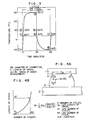
- The equivalent strain amplitude can be defined as follows. When the connection is subjected to the temperature cycle as shown in Fig. 3, the stress-strain curve occurring in the solder at the connection changes in accordance with the temperature change ① to ⑦ in this temperature cycle. This change in the stress-strain curve is shown as ① to ⑦ in Fig. 2 which can be acquired by the finite-element method three-dimensional thermal elastic/plastic analysis taking into consideration the temperature dependency of the real stress-real strain of the solder. Specifically, when in Fig. 3, temperature rises from the
initial state ① to 50°C (②), the maximum stress-strain of the solder (e.g. ②) stays anywhere in the real stress-real strain curve from ① to 50°C in Fig. 2. Likewise, one cycle of temperature change of 150°C → 50°C → 20°C → -50°C → 20°C results in the change in the stress-strain of ③ - ④ - ⑤ - ⑥ - ⑦. Then, assuming that this change corresponds to the stress-strain hysterisis curve shown in Fig. 1, its maximum equivalent amplitude Δεeqmax is defined as the strain range between ahigh temperature 150°C to a low temperature -50°C as shown in Fig. 2. The maximum equivalent amplitude Δεeqmax thus defined and the life Nf can be correlated with high accuracy irrespectively of the shape of the connection and the temperature range, as disclosed in the above mentioned extended abstracts. - Another object of the present invention is to provide a criterion equation for evaluating the life and a criterion equation for evaluating the degree of a crack using the maximum equivalent amplitude Δεeqmax and an equation representative of the speed of crack advancement; this crack advancement speed can be experimentally acquired in temperature cycle test by observing the braking face of the solder with the crack advanced by an electron microscope.
- In order to attain another object of the present invention, an approximation equation for acquiring the maximum equivalent strain amplitude Δεeqmax is simply obtained using the size of electronic components, the characteristic of the solder, and the condition of the temperature cycle; this approximation equation is programmed for a computer.
- The crack advancement speed equation permits the life of the connection to its final breakdown to be estimated before the final breakdown.
- The life evaluation criterion equation and the crack advancement criterion equation can give the number of temperature cycles for the degree of crack advancement permitted for assuring a remaining sectional area, and so gives the life of the connection. Contrary to this, these equations can also give the degree of crack advancement for the number of necessary cycles to know the remaining sectional area; a product can be designed so that it will not become poor within its life.
- The approximation equation for acquiring the maximum equivalent strain amplitude can give the maximum equivalent strain amplitude by a simple operation for a short time so that the life evaluation criterion equation and the crack advancement criterion equation acquired using the value of the maximum equivalent strain amplitude permits the life and the degree of crack advancement to be calculated, thereby designing an electronic device with high accuracy.
-
- Fig. 1 is a view of the conventional stress-strain hysterisis curve due to fatigue;
- Fig. 2 is a graph of the equivalent stress-strain curve of thermal fatigue which is adopted in an embodiment of the present invention;
- Fig. 3 is a graph showing the temperature profile used in an embodiment of the present invention;
- Fig. 4A is a conceptual view of the crack occurring in the solder between a semiconductor integrated circuit and a substrate in an embodiment of the present invention;
- Fig. 4B is a graph showing the relation between the length a of a crack and the number N of cycles giving rise to the life on the basis of the model of Fig. 4A;
- Fig. 5 is a side view of the solder connection between the semiconductor integrated circuit and the substrate which is a basis of the partially enlarged model of Fig. 4A;
- Fig. 6A is a graph showing a crack advancement speed equation da/dN = Aa + B which is defined by the relationship between the length a of a crack and a crack advancement speed;
- Figs. 6B and 6C are SEM images at a1 and a2 on the crack, respectively;
- Fig. 6D is a side view of the solder section where the semiconductor integrated circuit is mechanically removed from when the crack advances to point a2;
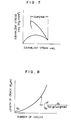
- Fig. 7 is a graph of an equivalent stress-strain curve at a point in a solder connection which is acquired by the method of Fig. 2 through the finite element method three-dimensional thermal elastic/plastic analysis;
- Fig. 8 is a graph showing the criterion for evaluating the life which is defined by the relationship between the crack length a and the cycle number N taking the equivalent strain into consideration;
- Fig. 9 is a side view showing the main size of each of the substrate, the solder and the electronic circuit component;
- Fig. 10 is a graph showing the strain evaluation criterion for acquiring the equivalent strain amplitude from a pure shearing strain;
- Fig. 11 is a flow chart of the program for performing an evaluation processing using the method according to the present invention; and
- Figs. 12A and 12B are views showing examples of display on a display device which are outputted as a result of the program processing of Fig. 11.
- An embodiment of the present invention will be explained with reference to the drawings. Fig. 5 shows the state where a semiconductor integrated
circuit 1 is connected with a circuit substrate through solders. If the temperature cycle of temperature changes due to power on/off of the circuit is repeated, because of a difference between the semiconductor integratedcircuit 1 and thecircuit substrate 2 in their thermal expansion coefficient, strains occur repeatedly in thesolder connections 3; eventually cracks as shown in the partially enlarged view of Fig. 4A. For each of the temperature cycles, this crack will advance by an interval da/dN and also a notch remains on the breaking face on which the crack occurs. The interval da/dN is referred to as a crack advancement speed (DB: diameter of connection). - After the electronic device shown in Fig. 5 has been subjected to 1000 (one thousand) cycles of temperature change, the semiconductor integrated
circuit 1 is mechanically removed therefrom. The faces of thecrack 4 thus formed, as shown in Fig. 6D, are observed using a scanning type electronic microscope (SEM). Figs. 6B and 6C show the observed images. The crack advancement speeds da/dN at the ends of the lengths of a1 and a2, which are obtained from the observed images of Figs. 6B and 6C, are ȧ1 and ȧ2. As a result of these observation results and other observations, as seen from Fig. 6A, the relationship between the crack advancement speed and the crack length a can be approximated as a linear relationship

- The life to breakdown estimated for the number of testing temperature cycles of 1000 is set for 3000 cycles; as a result of testing continued under the same condition, the breakdown was electrically confirmed at 3300 cycles approximate to the estimated 3000 cycles.
- Further, the solder connection structure shown in Fig. 5 is subjected to the temperature change corresponding to the testing temperature cycle of room temperature → +150°C → -50°C → room temperature through the finite element method three-dimensional thermal elastic/plastic analysis as shown in Fig. 2. Then, the
crack 4 as shown in Fig. 4A occurs in the solder connection structure. The hysterisis curve of the equivalent stress-equivalent strain at thecrack 4 is shown in Fig. 7. As seen from Fig. 7, the strain amplitude is defined as the maximum equivalent strain amplitude Δεeqmax. The relationship between the maximum equivalent amplitude Δεeqmax, and the crack advancing speed da/dN and the crack length a acquired in the previous breakdown test can be expressed by
- By integrating Equation (3), the life Nf can be acquired by the life evaluating criterion equation expressed by the following.
- By using Nf for expressing life number of cycles which causes fracture, a0 for an initial defect, af for a crack length when fractured, the above mentioned life evaluating criterion equation is expressed by,


- Further, by calculating backwards from Equation (4)-2, the crack length a after N cycles can be acquired by the crack advancement evaluating equation expressed by equation (5). These relations are exemplified in Fig. 8.

- With respect to poor products, the actual life thereof is 3500 cycles which is very approximate to the life of 3200 cycles acquired from calculation, where values of Δεeqmax ≒ 0.01 (=1%), A: 8.18 x 10⁻³, B: 0.18, C: 0.23, Af: 100 µm and ao: 0 are employed.
- Meanwhile, the maximum equivalent strain amplitude Δεeqmax, which is decisive for the life of the solder connection due to thermal fatigue, greatly depends on the size of the semiconductor integrated circuit and the environmental condition for the same connection structure; to acquire it through the infinite element method three-dimensional elastic/plastic analysis is very troublesome. Then, with reference to Fig. 10, a technique for simply acquiring the maximum equivalent strain amplitude Δεeqmax will be explained. Generally, the shearing strain γ at the connection as shown in Fig. 9 can be expressed by

circuit 1 and thecircuit substrate 2 in their thermal expansion coefficient ΔT is the temperature difference therebetween in their temperature cycles, and E is a correction parameter depending on the shape of the connection. The maximum equivalentstrain amplitudes Δε eqmax1,Δε eqmax2 andΔε eqmax3 corresponding to concrete values γ1, γ2, and γ3 can be simply acquired. The values γ1, γ2, and γ3 are obtained by a manual calculation of a structure model as shown in Figs. 12A, 12B in which certain dimensions are assigned, andΔε 

- In accordance with this embodiment, the life of the solder connection can be evaluated or estimated simply and correctly.
- Now explanation will be given for another embodiment of the present invention which realizes the life evaluation method according to the present invention through a program. The flowchart of the entire program is shown in Fig. 11. The screen image displayed when the shape of the solder connection of the electronic component (flip chip or CCB chip) is input, and that displayed when the result of life evaluation and the degree of crack advancement are output are shown in Figs. 12A and 12B.
- The evaluation through the program is carried out in the following process.
- In
Step 1, an object electronic component is designated by a key operation; for example, CCB is selected from a group consisting of CCB (Controlled Collapse Bonding), QFP (Quad Flat Package), PLCC (Plastic Leaded Chip Carrier), MSP (Mini Square Package), and flip chip etc. The selection operation inStep 1 displays the model of the CCB chip described by trigonometry as shown in Fig. 12A. With respect to thesubstrate 2, theCCB package chip 1 and thesolder 3 connecting them, the items indicated as the shape data to be input for the CCB model are the distance d from the package center to the solder; the width direction distance D and longitudinal direction distance L1 from the package center to the solder; the connecting width DB of thesolder 3 on the side of thepackage 1; that DP thereof on the side of thesubstrate 2; and the height HJ of the package from thesubstrate 2. - In
Step 2, the items or parameters required are input in such a manner that the respective columns of the list displayed for the CCB are filled with the corresponding data by a key operation. By filling the list with the required items in accordance with the items of the package model displayed by trigonometry, they can be surely input. - In
Step 3, thermal expansion coefficients of thesubstrate 2 and the package (CCB) are input. By this step, parameters, except for ΔT, required for calculation in equation (6) are input. - In
Step 4, Equation (4), which is a criterion equation for evaluating the life of the solder connection, and Equation (5), which is an equation for evaluating the crack advancement, are input, and further constants and an index n are input. These equations can be read out from the sub-routine including model equations prepared for each of the substrates and packages, and thereafter the contains and the index are substituted for the equations. - In
Step 5, analysis conditions such as the upper and lower limit temperatures in the temperature cycle, the repetition frequency thereof, and the temperature difference between the substrate and package are input. Then, inStep 6, if the program is operated, γ in equation (6) and Δεeqmax in equation (7) are sequentially calculated according to input parameters and analysis conditions. The obtained values in equations (6) and (7) are used to calculate life time in calculation of life time equation (4)-1 and crack advancement equation (5). - Finally, in
Step 7, the crack advancement on a section of the CCB model and on the solder pad surface as shown in Fig. 12B is displayed. The crack advancement display as shown in Fig. 12B also includes the display of the maximum temperature, the temperature difference between the substrate and package, the repetition frequency, the present number of temperature cycles and the present length of crack advancement. From these displays, the degree of crack advancement in the solder connection and the remaining life thereof can be easily evaluated. - Additionally, the above life evaluation process can be repeated from any step thereof, and can also be applied to a flat package IC and the other chip components.
- In accordance with the present invention, several calculations in the above program can be easily carried out using a large scale computer or a personal computer thereby the design the life of the electronic devices.
- The life number of temperature cycles and the life degree of crack advancement estimated for a sample prepared for life test in accordance with the present invention agree with those actually measured within an error range of ±10%. Also, the time required for estimation is as short as 5 - 10 minutes. this time is much shorter than 2 - 5 hours (measured in the CPU time) required to calculate the maximum equivalent strain amplitude through the infinite element method using a super computer S810 in the previous embodiment. In short, in accordance with the present invention, the process for evaluating the life of the solder connection of an electronic component, which has been difficult, can be carried out in a short time and at low cost using a personal computer or a large scale computer.
- Further, the life of the connection can be evaluated through the infinite element method three-dimensional thermal elastic/plastic analysis for any temperature distribution and environmental condition; it can be evaluated with high accuracy. Thus, the life evaluation method according to the present invention can contribute to enhance the reliability of electronic devices which will be strictly demanded in the future.
Claims (18)
- A method for diagnosing a connection life of a solder connection (3) between a substrate (2) and parts (1) loaded thereon, said method being performed by a computer, said computer having input means for inputting information and processing means for processing said input information and outputting a result of said processing, said method comprising the steps of:a) preparing a plurality of solder connections (3) of the same connection structure with different connection parameters;b) determining by said processing means shearing strains and equivalent strain amplitudes of each of said solder connections (3) to determine an approximated shearing strain/equivalent strain amplitude correlation model pertinent to a corresponding one of said solder connections;c) applying a number of heat cycles to said solder connections (3) to cause cracks in each of said solder connections;d) measuring a total crack length after said heat cycles and a particular crack advancement caused by the very last cycle of said heat cycles to obtain a crack length/crack advancement speed correlation model;e) determining a solder connection life diagnosing model with said equivalent strain amplitude by integrating said crack length/crack advancement speed correlation model;f) measuring a shearing strain of a solder connection (3) to be diagnosed of said same connection structure with a desired parameter to obtain a corresponding equivalent strain amplitude by using said approximated shearing strain/equivalent strain amplitude correlation model; andg) determining a connection life if said solder connection (3) with said desired parameter by applying said equivalent strain amplitude of said solder connection with said desired parameter into said connection life diagnosing model.
- The method for diagnosing a connection life of a solder connection (3) according to claim 1, wherein said relationship between said values of said equivalent strain amplitudes is represented by

- The method for diagnosing a connection life of a solder connection (3) according to claim 1, wherein said connection life diagnosing model is represented by the equation:

- The method for diagnosing a connection life of a solder connection (3) according to claim 1, wherein a model for diagnosing the advancement of a crack is made using said equivalent strain amplitudes, and said equivalent strain amplitude is substituted into said model for diagnosing crack advancement to diagnose the length of the crack.
- The method for diagnosing a connection life for a solder connection life for a solder connection according to claim 4, wherein said model for diagnosing crack advancement is represented by

- The method for diagnosing a connection life of a solder connection according to claim 1, wherein said life of the connection is defined as the number of heat cycles at which the connection is broken.
- The method for diagnosing a connection life of solder connection according to claim 1, wherein said values of said equivalent strain amplitudes are acquired from the relationship between said values of said equivalent strain amplitudes, which are prepared by a finite element method three-dimensional thermal elastic/plastic analysis, and said values of said shearing strains.
- The method for diagnosing a connection life of a solder connection (3) according to claim 1, wherein said parts loaded on said substrate (2) comprise an electronic device, and said shearing strain occurs in said solder connection (3).
- The method for diagnosing a connection life of a solder connection (3) according to claim 5, wherein said parts loaded on said substrate (2) comprise chip parts (1) connected with said substrate through said solder connection (3).
- The method for diagnosing a connection life of a solder connection (3) according to claim 9, wherein said chip parts (1) are any one selected from the group consisting of CCB (Controlled Collapse Bonding), QFP (Quad Flat Package), PLCC (Plastic Leaded Chip Carrier), MSP (Mini Square Package), flip chip, condenser and resister.
- The method for diagnosing a connection life of a solder connection (3) according to claim 5, wherein said shearing strain τ is defined as

- The method for diagnosing a connection life of a solder connection (3) according to claim 1, wherein said result of said processing is displayed at display means, said method comprising the steps of:a) inputting by said input means parameters of a plurality of different solder connections (3) of the same connection structure;b) calculating by said processing means shearing strains of said plurality of different solder connections (3);c) calculating by said processing means equivalent strain amplitude corresponding to thermal fatigue life time for each of the values of said plurality of shearing strains;d) defining by said processing means a relationship between said shearing strains and said equivalent strain amplitudes;e) formulating by said processing means a life evaluation criterion equation expressed using said equivalent strain amplitudes;f) inputting by said input means a total crack length and a particular crack advancement by the very last cycle of a number of heat cycles applied to said plurality of different solder connections (3);g) determining by said processing means a crack length/crack advancement speed correlation model, thereby obtaining solder connection life diagnosing model with said equivalent strain amplitude;h) inputting a desired parameter of said solder connection (3) to be diagnosed of said same connection structure;j) determining by said processing means a corresponding equivalent strain amplitude corresponding to said desired parameter by using a relationship between said shearing strain and said equivalent strain amplitudes;k) substituting said equivalent strain amplitudes for the life evaluation criterion equation to acquire the connection life of said desired parameter; andl) displaying by said display means the life of said connection;i) wherein an equation for diagnosing the advancement of a crack is made using said equivalent strain amplitudes, and said equivalent strain amplitude is substituted for a crack advancement diagnosing equation to calculate the length of the crack;ii) wherein said inputting step includes the steps of defining a member for which the life of the solder connection (3) is to be diagnosed to display on said display means a shape model of the member,m) inputting by said input means required parameters representative of the shape of the connection (3) in accordance with the shape model displayed on said display means;n) inputting required material constants for the member to be evaluated;o) inputting an analysis condition of the member to be evaluated;p) performing by said processing means a calculation in accordance with said solder connection life diagnosing model and said crack advancement diagnosing equation; andq) wherein said displaying step includes the step of displaying the calculation result as a length of the crack on the shape model on the display means, and illustrating said diagnosing result on a solder connection life diagnosing graph representative of the relationship between the number of temperature cycles and the length of the crack.
- The method for diagnosing a connection life of a solder connection (3) according to claim 12, wherein said solder connection life diagnosing model and said crack advancement diagnosing equation are stored in a memory of said computer as a sub-routine after being once obtained.
- The method for diagnosing a connection life of a solder connection (3) according to claim 12, wherein said step of defining the member (1, 2, 3) is performed by selecting a chip part (1); and wherein said chip part is selected from any one of a group consisting of CCB (Controlled Collapse Bonding), QFP (Quad Flat Pakkage), PLCC (Plastic Leaded Chip Carrier), MSP (Mini Square Package), flip chip, condenser and resister.
- The method for diagnosing a connection life of a solder connection (3) according to claim 12, wherein said shape model shows the connection relationship between the members (1, 2, 3) by trigonometry.
- The method for diagnosing a connection life of a solder connection (3) according to claim 12, wherein sa<id parameters comprise the size of each of the members (1, 2, 3) and the size of a gap between said members.
- The method for diagnosing a connection life of a solder connection (3) according to claim 12, wherein said material constants comprise the thermal expansion coefficient of each of said members (1, 2, 3).
- The method for diagnosing a connection life of a solder connection (3) according to claim 12, wherein said analysis condition comprises a temperature difference, and a repetition frequency.
Applications Claiming Priority (2)
| Application Number | Priority Date | Filing Date | Title |
|---|---|---|---|
| JP8792789 | 1989-04-10 | ||
| JP87927/89 | 1989-04-10 |
Publications (3)
| Publication Number | Publication Date |
|---|---|
| EP0392471A2 EP0392471A2 (en) | 1990-10-17 |
| EP0392471A3 EP0392471A3 (en) | 1991-09-11 |
| EP0392471B1 true EP0392471B1 (en) | 1997-01-02 |
Family
ID=13928552
Family Applications (1)
| Application Number | Title | Priority Date | Filing Date |
|---|---|---|---|
| EP19900106875 Expired - Lifetime EP0392471B1 (en) | 1989-04-10 | 1990-04-10 | Method for evaluating life of connection |
Country Status (2)
| Country | Link |
|---|---|
| EP (1) | EP0392471B1 (en) |
| DE (1) | DE69029530T2 (en) |
Cited By (2)
| Publication number | Priority date | Publication date | Assignee | Title |
|---|---|---|---|---|
| WO2011116753A3 (en) * | 2010-03-23 | 2011-11-17 | Mtu Aero Engines Gmbh | Method and device for determining a material response in a structural part |
| CN110579399A (en) * | 2019-09-18 | 2019-12-17 | 中国核动力研究设计院 | Method for predicting quasi-static uniaxial tension real fracture stress of metal material |
Families Citing this family (11)
| Publication number | Priority date | Publication date | Assignee | Title |
|---|---|---|---|---|
| BG64998B1 (en) * | 2001-12-21 | 2006-11-30 | Донка АНГЕЛОВА | Method for testsing structural materials fatigue |
| ES2273195T3 (en) * | 2004-01-27 | 2007-05-01 | Abb Research Ltd. | ESTIMATION OF AN IRREVERSIBLE AGING BEHAVIOR. |
| JP4756033B2 (en) * | 2005-03-18 | 2011-08-24 | 富士通株式会社 | Electronic package evaluation apparatus, electronic package optimization apparatus, and computer-readable recording medium recording electronic package evaluation program |
| DE102010021171A1 (en) * | 2010-05-21 | 2011-11-24 | Siemens Aktiengesellschaft | Device for determining service life of electronic structure e.g. electrical converter, has computing unit computing service life of electronic structure from determined temperature and electrical size of electronic structure |
| JP5641998B2 (en) * | 2011-03-25 | 2014-12-17 | 三菱電機株式会社 | Semiconductor device lifetime estimation method |
| DE102013224527A1 (en) * | 2013-11-29 | 2015-06-03 | Siemens Aktiengesellschaft | A method of determining an optimum axial overlap length for an overlap solder joint and a component having an overlap solder joint |
| DE102014203606A1 (en) * | 2014-02-27 | 2015-08-27 | Robert Bosch Gmbh | Method for monitoring the thermal load of balancing resistors |
| CN112730112B (en) * | 2020-12-18 | 2022-07-01 | 苏州热工研究院有限公司 | Environment fracture evaluation method suitable for reactor structural component material after long-term service |
| CN114330054A (en) * | 2021-12-17 | 2022-04-12 | 江苏龙城精锻集团有限公司 | Method for efficiently determining fatigue life of oil rail part |
| DE102022101537A1 (en) | 2022-01-24 | 2023-07-27 | Bayerische Motoren Werke Aktiengesellschaft | Method and device for determining service life information for a solder joint of an electronic assembly |
| DE102024202570A1 (en) | 2024-03-19 | 2025-09-25 | Robert Bosch Gesellschaft mit beschränkter Haftung | Method and apparatus for estimating a lifetime of a solder joint in an electronic component |
-
1990
- 1990-04-10 EP EP19900106875 patent/EP0392471B1/en not_active Expired - Lifetime
- 1990-04-10 DE DE1990629530 patent/DE69029530T2/en not_active Expired - Fee Related
Cited By (3)
| Publication number | Priority date | Publication date | Assignee | Title |
|---|---|---|---|---|
| WO2011116753A3 (en) * | 2010-03-23 | 2011-11-17 | Mtu Aero Engines Gmbh | Method and device for determining a material response in a structural part |
| CN110579399A (en) * | 2019-09-18 | 2019-12-17 | 中国核动力研究设计院 | Method for predicting quasi-static uniaxial tension real fracture stress of metal material |
| CN110579399B (en) * | 2019-09-18 | 2022-03-01 | 中国核动力研究设计院 | Method for predicting quasi-static uniaxial tension real fracture stress of metal material |
Also Published As
| Publication number | Publication date |
|---|---|
| EP0392471A3 (en) | 1991-09-11 |
| DE69029530T2 (en) | 1997-08-07 |
| DE69029530D1 (en) | 1997-02-13 |
| EP0392471A2 (en) | 1990-10-17 |
Similar Documents
| Publication | Publication Date | Title |
|---|---|---|
| US5291419A (en) | Method for diagnosing the life of a solder connection | |
| Subrahmanyan et al. | A damage integral approach to thermal fatigue of solder joints | |
| EP0392471A2 (en) | Method for evaluating life of connection | |
| US20060294436A1 (en) | Appararus for predicting reliability in electronic device package, program for predicting reliability in electronic device package, and method for predicting reliability in electronic device package | |
| US20090048788A1 (en) | Rapid determination of fatigue failure based on temperature evolution | |
| JP2013058657A (en) | Electronic device life estimation method and electronic device design method using the same | |
| JP2791174B2 (en) | Electronic component solder connection life evaluation method | |
| CN116070476A (en) | A method and system for simulation of solder joint reliability of electronic components | |
| Pang et al. | Sensitivity study of temperature and strain rate dependent properties on solder joint fatigue life | |
| Lall et al. | Mechanical properties of doped solder SAC-Q for high strain rate testing at extreme surrounding temperatures for 6 months of isothermal aging | |
| US20040158450A1 (en) | Solder joint life prediction method | |
| Tien et al. | Creep-fatigue interactions in solders | |
| Wen et al. | Comparison of LCC solder joint life predictions with experimental data | |
| Stolkarts et al. | Constitutive and damage model for solders | |
| Höhne et al. | Effect of temperature on vibration durability of lead-free solder joints | |
| CN114141319A (en) | Method for rapidly and accurately characterizing viscoelastic parameters of material | |
| JP2005148016A (en) | Thermal fatigue life diagnosis method and apparatus for solder joints | |
| Gharaibeh et al. | Anand Model Constants of Sn–Ag–Cu Solders: What Do They Actually Mean? | |
| Kuczynska et al. | Effect of shear and tensile-dominant cyclic loading on failure in SnAgCu solder | |
| Qian et al. | On the life prediction and accelerated testing of solder joints | |
| Jiang | Anisotropic Multi-scale Modeling for Steady-state Creep Behavior of Oligocrystalline SnAgCu (SAC) Solder Joints | |
| CN112417740B (en) | Accurate measurement method for low-temperature fracture elongation of aluminum alloy for aerospace | |
| JP2004085397A (en) | Life estimation method for solder joints | |
| Zukowski et al. | Correct modelling of geometry and materials properties in the thermo-mechanical finite-elements-simulation of chip scale packages | |
| Kuczynska et al. | Numerical Prediction of Failure in SnAgCu solder under shear and tensile-dominant cyclic loading |
Legal Events
| Date | Code | Title | Description |
|---|---|---|---|
| PUAI | Public reference made under article 153(3) epc to a published international application that has entered the european phase |
Free format text: ORIGINAL CODE: 0009012 |
|
| 17P | Request for examination filed |
Effective date: 19900410 |
|
| AK | Designated contracting states |
Kind code of ref document: A2 Designated state(s): DE NL |
|
| PUAL | Search report despatched |
Free format text: ORIGINAL CODE: 0009013 |
|
| RAP1 | Party data changed (applicant data changed or rights of an application transferred) |
Owner name: HITACHI MICROCOMPUTER SYSTEM LTD. Owner name: HITACHI, LTD. |
|
| AK | Designated contracting states |
Kind code of ref document: A3 Designated state(s): DE NL |
|
| RHK1 | Main classification (correction) |
Ipc: G01N 3/00 |
|
| 17Q | First examination report despatched |
Effective date: 19931216 |
|
| GRAG | Despatch of communication of intention to grant |
Free format text: ORIGINAL CODE: EPIDOS AGRA |
|
| GRAH | Despatch of communication of intention to grant a patent |
Free format text: ORIGINAL CODE: EPIDOS IGRA |
|
| GRAH | Despatch of communication of intention to grant a patent |
Free format text: ORIGINAL CODE: EPIDOS IGRA |
|
| GRAH | Despatch of communication of intention to grant a patent |
Free format text: ORIGINAL CODE: EPIDOS IGRA |
|
| GRAA | (expected) grant |
Free format text: ORIGINAL CODE: 0009210 |
|
| AK | Designated contracting states |
Kind code of ref document: B1 Designated state(s): DE NL |
|
| REF | Corresponds to: |
Ref document number: 69029530 Country of ref document: DE Date of ref document: 19970213 |
|
| PLBE | No opposition filed within time limit |
Free format text: ORIGINAL CODE: 0009261 |
|
| STAA | Information on the status of an ep patent application or granted ep patent |
Free format text: STATUS: NO OPPOSITION FILED WITHIN TIME LIMIT |
|
| 26N | No opposition filed | ||
| PGFP | Annual fee paid to national office [announced via postgrant information from national office to epo] |
Ref country code: DE Payment date: 20080606 Year of fee payment: 19 |
|
| PGFP | Annual fee paid to national office [announced via postgrant information from national office to epo] |
Ref country code: NL Payment date: 20080326 Year of fee payment: 19 |
|
| NLV4 | Nl: lapsed or anulled due to non-payment of the annual fee |
Effective date: 20091101 |
|
| PG25 | Lapsed in a contracting state [announced via postgrant information from national office to epo] |
Ref country code: DE Free format text: LAPSE BECAUSE OF NON-PAYMENT OF DUE FEES Effective date: 20091103 |
|
| PG25 | Lapsed in a contracting state [announced via postgrant information from national office to epo] |
Ref country code: NL Free format text: LAPSE BECAUSE OF NON-PAYMENT OF DUE FEES Effective date: 20091101 |