EP0391026A2 - Device for decoupling two pipe parts - Google Patents
Device for decoupling two pipe parts Download PDFInfo
- Publication number
- EP0391026A2 EP0391026A2 EP90101256A EP90101256A EP0391026A2 EP 0391026 A2 EP0391026 A2 EP 0391026A2 EP 90101256 A EP90101256 A EP 90101256A EP 90101256 A EP90101256 A EP 90101256A EP 0391026 A2 EP0391026 A2 EP 0391026A2
- Authority
- EP
- European Patent Office
- Prior art keywords
- damper
- cushion
- damper cushion
- pipe
- contour
- Prior art date
- Legal status (The legal status is an assumption and is not a legal conclusion. Google has not performed a legal analysis and makes no representation as to the accuracy of the status listed.)
- Granted
Links
Images


Classifications
-
- F—MECHANICAL ENGINEERING; LIGHTING; HEATING; WEAPONS; BLASTING
- F16—ENGINEERING ELEMENTS AND UNITS; GENERAL MEASURES FOR PRODUCING AND MAINTAINING EFFECTIVE FUNCTIONING OF MACHINES OR INSTALLATIONS; THERMAL INSULATION IN GENERAL
- F16L—PIPES; JOINTS OR FITTINGS FOR PIPES; SUPPORTS FOR PIPES, CABLES OR PROTECTIVE TUBING; MEANS FOR THERMAL INSULATION IN GENERAL
- F16L55/00—Devices or appurtenances for use in, or in connection with, pipes or pipe systems
- F16L55/04—Devices damping pulsations or vibrations in fluids
-
- F—MECHANICAL ENGINEERING; LIGHTING; HEATING; WEAPONS; BLASTING
- F01—MACHINES OR ENGINES IN GENERAL; ENGINE PLANTS IN GENERAL; STEAM ENGINES
- F01N—GAS-FLOW SILENCERS OR EXHAUST APPARATUS FOR MACHINES OR ENGINES IN GENERAL; GAS-FLOW SILENCERS OR EXHAUST APPARATUS FOR INTERNAL COMBUSTION ENGINES
- F01N13/00—Exhaust or silencing apparatus characterised by constructional features ; Exhaust or silencing apparatus, or parts thereof, having pertinent characteristics not provided for in, or of interest apart from, groups F01N1/00 - F01N5/00, F01N9/00, F01N11/00
- F01N13/18—Construction facilitating manufacture, assembly, or disassembly
- F01N13/1805—Fixing exhaust manifolds, exhaust pipes or pipe sections to each other, to engine or to vehicle body
- F01N13/1811—Fixing exhaust manifolds, exhaust pipes or pipe sections to each other, to engine or to vehicle body with means permitting relative movement, e.g. compensation of thermal expansion or vibration
-
- F—MECHANICAL ENGINEERING; LIGHTING; HEATING; WEAPONS; BLASTING
- F16—ENGINEERING ELEMENTS AND UNITS; GENERAL MEASURES FOR PRODUCING AND MAINTAINING EFFECTIVE FUNCTIONING OF MACHINES OR INSTALLATIONS; THERMAL INSULATION IN GENERAL
- F16L—PIPES; JOINTS OR FITTINGS FOR PIPES; SUPPORTS FOR PIPES, CABLES OR PROTECTIVE TUBING; MEANS FOR THERMAL INSULATION IN GENERAL
- F16L55/00—Devices or appurtenances for use in, or in connection with, pipes or pipe systems
- F16L55/02—Energy absorbers; Noise absorbers
- F16L55/033—Noise absorbers
- F16L55/0332—Noise absorbers by inserting a body of compressible material in the pipe
Definitions
- the invention relates to a device for the vibration decoupling of two pipe parts, in particular a gas-tight metal bellows coupling between an exhaust pipe of a motor vehicle engine and the exhaust system, with at least one damper cushion pressed from wire mesh, knitted wire mesh, or the like.
- Such devices are known from DE-OS 33 21 382, DE-OS 36 22 481 and EP-OS 208 128.
- the devices have good damping behavior in preferred directions, while the damping behavior in other directions is substantially, in some cases orders of magnitude worse.
- the damper cushion of EP-OS 208 128 cannot dampen any torsional movements that completely penetrate the bellows.
- the latter is avoided with the configuration of DE-OS 36 22 481 by decoupling torsional movements there; damping is therefore not provided here.
- the invention is therefore based on the object of further developing a device of the generic type in such a way that optimal damping in all, at one Such device occurring, directions of movement is achieved.
- the stated object is achieved in a device for vibration-related decoupling of two pipe parts, in particular between an exhaust pipe of a motor vehicle engine and the exhaust system, with at least one damper cushion pressed from wire mesh, knitted wire mesh, or the like, in that the damper cushion is polygonal.
- polygonal in such a spatial damper cushion means that there are corners in which at least three sharp edges converge.
- the polygon distinguishes the subject of the application from cylindrical, cylindrical-shaped, truncated-conical, frustoconical-shaped damper cushions, which have edges as a transition from their lateral surfaces to their base surfaces, but no corners in the aforementioned sense.
- their lateral surfaces are formed continuously and have no edges which are present in them due to the polygonal design of the damper cushions of the subject of the application.
- the damper cushions according to the invention therefore have, in addition to their edges between lateral surfaces and base surfaces, also edges between individual lateral surface areas.
- damper cushions with a circular base surface can in no way absorb circumferential forces acting tangentially on their jacket, this is made possible in the embodiment of the damper cushion according to the invention by the formation of edges in the jacket, so that the housing parts can no longer freely rotate in the jacket region, as is the case with the prior art, but is prevented from doing so by the edges in the jacket.
- the damper cushions designed according to the invention generally have a multiple, but not infinitely countable rotational symmetry axis perpendicular to their base areas. As with a variety of edges in the jacket or corners of the base, the resistance forces exerted on these are reduced against corresponding movements, it is preferably provided that the damper cushion has a hexagonal to hexagonal base plane, the damper cushion having a square base plane.
- the damper cushion basically has a rectangular outer contour, or that the damper cushion has a truncated pyramid-like outer contour.
- the end faces of the damper cushion do not have to form one plane, but it can be provided, for example, that diagonally opposite corners of the end faces with the lateral surfaces each lie in one plane, but are mutually offset in the direction of the axis of the damper cushion itself.
- the housings receiving the damper cushions are fundamentally adapted to the basic shape of the respective damper cushion described.
- a housing receiving the damper cushion is formed by a damper outer socket adapted to the outer contour of the damper cushion and connected to one pipe end and by a damper inner socket adapted to the inner contour of the damper cushion and connected to the other pipe end.
- the outer and inner frames are of shell-like design, it being possible on the one hand to provide that the damper cushions are arranged with their side edges parallel to the axis of symmetry of the pipe ends in the unloaded state or that the damper cushions are parallel to the axis A of the pipe ends Are aligned diagonally.
- the housings also protect the damper cushions and in particular the bellows against stone chipping and splashing water, as well as sound radiation protection, so that additional protection is not required. Furthermore, they can be used as Angular overload protection should be formed, the maximum angle is preferably limited to 5 to 10 °.
- the design according to the invention creates a decoupling device which, regardless of the installation position, ensures optimal damping of all movements that occur and ensures uniform damping over all degrees of freedom.
- a fixation against torsional forces acting on the jacket of the damper cushion and a damping thereof are made possible, whereby damping against angular movements about the axis of symmetry of the damper cushion is achieved.
- two damper cushions are provided diagonally to the main axis of the device and thus the pipe ends, these can also be offset relative to such a linear arrangement around the main pipe axis so that they enclose an angle of less than 180 degrees.
- the preferred density of the cushion is between 1, 4 and 1.8 kg / dm3.
- the preferred cushion height is between 5 and 15 mm with a tube diameter of 50 mm.
- the pillow height should preferably be in a corresponding ratio to these.
- the preferred ratio between pillow thickness a and height 1 is between 2: 1 and 4: 1.
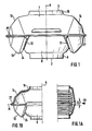
- the device according to the invention for decoupling second pipe parts has two pipe ends 2, 3 in the exemplary embodiment shown on pipe connections 4, 6, which are flexibly connected to one another via a bellows 7 surrounding them.
- a damping transmission body 8 On the pipe socket 4 sits concentrically and firmly connected to it (as by welding), a damping transmission body 8, which is ring-shaped or sleeve-shaped in its fastening area 9 with the pipe socket 4, from which a pyramid-shaped inner frame 11 for a damper cushion 12 extends, that forms an inner or lower part of an enclosure for the damper cushion.
- the outer or upper part of the damper cushion is formed by a correspondingly shaped, truncated pyramid-shaped damper outer mount 13, which is formed on an outer damper transmission body 14, which also has a sleeve or ring section 16 with which it rests on the end 3 of the other pipe section 6 .
- an outer damper transmission body 14 which also has a sleeve or ring section 16 with which it rests on the end 3 of the other pipe section 6 .
- Between the inner and outer frame 11, 13 sits the generally truncated pyramid-shaped damper cushion 12 and lies with its outer and inner side walls 17, 18 on the outer or Inner frame 13, 11, while it is held on its upper and lower end faces 21, 22 by bends 23, 24 of the frame parts 11, 13.
- the damper cushion 12 sits relative to the axis A of the pipe sections 4, 6 (in the unloaded state) in such a way that the diagonal of its base area, as well as its axis of symmetry, is perpendicular to the pipe axis 8.
- the inner frame 11 is with their wing areas for Damper cushion 12 on the side facing the ring area 9 is formed integrally with the ring area 9 relative to the axis-perpendicular central plane M of the arrangement, while the supporting parts of the inner frame lying beyond the center axis M are formed as a separate part and are connected to the aforementioned part by welding (at 26) .
- it can also be formed in one piece with the connecting part 2, as a result of which the number of parts is further reduced in an economical manner.
- pressure joints can also be provided.
- the parts of the outer damper transmission body 14 which are formed between the ring region 16 and the center plane M which is perpendicular to the axis are formed in one piece, while the supporting parts located beyond the center plane are welded in the region of the center plane M (at 27).
- the configuration according to the invention creates a device which enables largely the same vibration damping in all directions or with respect to all occurring movements and has no highlighted directions which do not allow damping, as is the case in the prior art.
- angular movements of the pipe sections 4, 6 about the axis of symmetry of the pillows 12 are absorbed due to the polygonal or polygonal configuration of the pillows.
- FIG. 1 with regard to axial, angular movements of the central axes of the two cushions and torsional movements of the pipe sections 4, 6 about the axis of symmetry A.
- FIGS. 5 to 7 also show an arrangement in which the damper cushions 12 lie diagonally to the axis A, although the damper cushions are not arranged diagonally, but rather their side walls or edges are aligned parallel or perpendicular to the axis of symmetry A. 8 to 10, the damper cushions 12 are aligned in the same way as in the embodiment of FIGS. 5 to 7, but are no longer diagonally opposite, but are offset by a certain angle about the axis of symmetry A of the arrangement, so that they include, for example, a relative angle of 135 degrees to axis A in the illustrated embodiment.
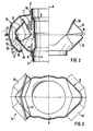
- FIGS. 11 to 13 show vertical side views or a top view of a preferred embodiment of a damper cushion 12, as used, for example, in the embodiment of FIGS. 1 to 4.
- Auxiliary lines are shown in dash-dotted lines, while concealed boundary lines of the pillow 12 are shown interrupted.
- the basic shape of the pillow is that of a pyramid or a pyramid shell, although not (Fig. 13) with a square, but diamond-shaped base.
- the corners of the cushion 12 (in which three edges converge in each case) are not all in one plane perpendicular to the axis of symmetry S of the cushion, but rather in each case diagonal corners are in one plane to the axis S, but opposite one another in the direction of the axis S. are offset.
- the pillow can have different shapes, but it is essential that any cut surface has at least three corners and preferably up to six, most preferably four corners each and does not have an annular, circular or even elliptical contour, as is the case with cylinders, Cylinder jackets, a cone or the like is regularly the case, the circumferential or tangential forces do not regularly absorb and therefore can not dampen.
Abstract
Description
Die Erfindung betrifft eine Vorrichtung zur schwingungstechnischen Entkopplung zweier Rohrteile, insbesondere einer gasdichten Matallbalgentkopplung zwischen einem Abgasrohr eines Kraftfahrzeugmotors und der Abgasanlage, mit mindestens einem aus Drahtgeflecht, -gestricke, -wirrlage oder dergleichen verpreßten Dämpferkissen. Derartige Vorrichtungen sind aus der DE-OS 33 21 382, der DE-OS 36 22 481 und der EP-OS 208 128 bekannt. Die Vorrichtungen weisen ein gutes Dämpfungsverhalten in bevorzugten Richtungen auf, während das Dämpfungsverhalten in anderen Richtungen wesentlich, teilweise um Größenordnungen schlechter ist. So kann beispielsweise das Dämpferkissen der EP-OS 208 128 keinerlei Torsionsbewegungen abdämpfen, die vollständig auf den Balg durchschlagen. Letzteres wird zwar mit der Ausgestaltung der DE-OS 36 22 481 vermieden, indem dort eine Entkopplung von Torsionsbewegungen vorgenommen wird; eine Dämpfung ist hier aber demgemäß gerade nicht vorgesehen. Der Erfindung liegt daher die Aufgabe zugrunde, eine Vorrichtung der gattungsgemäßen Art dahingehend weiterzuentwickeln, daß eine optimal Dämpfung in sämtlichen, bei einer derartigen Vorrichtung auftretenden, Bewegungsrichtungen erzielt wird.The invention relates to a device for the vibration decoupling of two pipe parts, in particular a gas-tight metal bellows coupling between an exhaust pipe of a motor vehicle engine and the exhaust system, with at least one damper cushion pressed from wire mesh, knitted wire mesh, or the like. Such devices are known from DE-OS 33 21 382, DE-OS 36 22 481 and EP-OS 208 128. The devices have good damping behavior in preferred directions, while the damping behavior in other directions is substantially, in some cases orders of magnitude worse. For example, the damper cushion of EP-OS 208 128 cannot dampen any torsional movements that completely penetrate the bellows. The latter is avoided with the configuration of DE-OS 36 22 481 by decoupling torsional movements there; damping is therefore not provided here. The invention is therefore based on the object of further developing a device of the generic type in such a way that optimal damping in all, at one Such device occurring, directions of movement is achieved.
Erfindungsgemäß wird die genannte Aufgabe bei einer Vorrichtung zur schwingungstechnischen Entkopplung zweier Rohrteile, insbesondere zwischen einem Abgasrohr eines Kraftfahrzeugmotors und der Abgasanlage, mit mindestens einem aus Drahtgeflecht, -gestricke, -wirrlage oder dergleichen verpreßten Dämpferkissen dadurch gelöst, daß das Dämpferkissen mehreckig ausgebildet ist.According to the invention, the stated object is achieved in a device for vibration-related decoupling of two pipe parts, in particular between an exhaust pipe of a motor vehicle engine and the exhaust system, with at least one damper cushion pressed from wire mesh, knitted wire mesh, or the like, in that the damper cushion is polygonal.
Die Angabe "mehreckig" beinhaltet bei einem derartigen räumlichen Dämpferkissen, daß Ecken vorhanden sind, in denen mindestens drei scharfe Kanten jeweils zusammenlaufen. Die Mehreckigkeit grenzt den Anmeldungsgegenstand ab gegenüber zylinder-, zylindermantelförmigen, kegelstumpfförmigen, kegelstumpfmantelförmigen Dämpferkissen, die zwar als Übergang von ihren Mantelflächen zu ihren Grundflächen Kanten, aber keine Ecken im vorgenannten Sinne aufweisen. Insbesondere sind ihre Mantelflächen stetig ausgebildet und weisen keine Kanten auf, die durch die vorausgesetzte mehreckige Ausbildung der Dämpferkissen des Anmeldungsgegenstandes bei diesen vorhanden sind. Die erfindungsgemäßen Dämpferkissen weisen daher neben ihren Kanten zwischen Mantelflächen und Grundflächen auch Kanten zwischen einzelnen Mantelflächenbereichen auf. Während die genannten bekannten Dämpferkissen mit kreisförmiger Grundfläche tangential an ihrem Mantel angreifende Umfangskräfte in keiner Weise aufnehmen können, wird dies bei der erfindungsgemäßen Ausgestaltung der Dämpferkissen durch die Ausbildung von Kanten im Mantel ermöglicht, so daß die Gehäuseteile im Mantelbereich sich nicht mehr frei verdrehen können, wie dies beim Stand der Technik der Fall ist, sondern hieran durch die Kanten im Mantel gehindert werden. Die erfindungsgemäß ausgestalteten Dämpferkissen weisen in der Regel eine mehrzählige, aber nicht unendlich zählige Drehsymmetrieachse senkrecht zu ihren Grundflächen auf. Da mit einer Vielzahl von Kanten im Mantel bzw. Ecken der Grundfläche, die an diesen ausgeübten Widerstandskräfte gegen entsprechende Bewegungen reduziert werden, ist vorzugsweise vorgesehen, daß das Dämpferkissen eine zwei- bis sechseckige Grundebene aufweist, wobei das Dämpferkissen eine viereckige Grundebene aufweist. Wenn in letzterem Falle eine Vierzähligkeit der gegebenenfalls vorhandenen Symmetrieachse vorhanden sein kann, so kann in gleicher Weise auch Zweizähligkeit gegeben sein, indem beispielsweise die Grundfläche des Dämpferkissens nicht quadratisch, sondern beispielsweise rautenförmig ausgebildet ist. Weitere bevorzugte Ausgestaltungen sehen vor, daß das Dämpferkissen grundsätzlich quaderförmige Außenkontur, bzw. daß das Dämpferkissen pyramidenstumpfartige Außenkontur aufweist. Dabei müssen die Stirnseiten der Dämpfergskissen nicht eine Ebene bilden, sondern es kann zum Beispiel vorgesehen sein, daß diagonal gegenüberliegende Ecken der Stirnseiten mit den Mantelflächen zwar jeweils in einer Ebene liegen, zueinander aber in Richtung der Achse des Dämpferkissens selbst zueinander versetzt sind.The specification "polygonal" in such a spatial damper cushion means that there are corners in which at least three sharp edges converge. The polygon distinguishes the subject of the application from cylindrical, cylindrical-shaped, truncated-conical, frustoconical-shaped damper cushions, which have edges as a transition from their lateral surfaces to their base surfaces, but no corners in the aforementioned sense. In particular, their lateral surfaces are formed continuously and have no edges which are present in them due to the polygonal design of the damper cushions of the subject of the application. The damper cushions according to the invention therefore have, in addition to their edges between lateral surfaces and base surfaces, also edges between individual lateral surface areas. While the known damper cushions with a circular base surface can in no way absorb circumferential forces acting tangentially on their jacket, this is made possible in the embodiment of the damper cushion according to the invention by the formation of edges in the jacket, so that the housing parts can no longer freely rotate in the jacket region, as is the case with the prior art, but is prevented from doing so by the edges in the jacket. The damper cushions designed according to the invention generally have a multiple, but not infinitely countable rotational symmetry axis perpendicular to their base areas. As with a variety of edges in the jacket or corners of the base, the resistance forces exerted on these are reduced against corresponding movements, it is preferably provided that the damper cushion has a hexagonal to hexagonal base plane, the damper cushion having a square base plane. If, in the latter case, there can be a four-fold number of the axis of symmetry that may be present, then there can be a two-fold number in the same way, for example in that the base area of the damper cushion is not square, but is, for example, diamond-shaped. Further preferred refinements provide that the damper cushion basically has a rectangular outer contour, or that the damper cushion has a truncated pyramid-like outer contour. The end faces of the damper cushion do not have to form one plane, but it can be provided, for example, that diagonally opposite corners of the end faces with the lateral surfaces each lie in one plane, but are mutually offset in the direction of the axis of the damper cushion itself.
Die die Dämpferkissen aufnehmenden Gehäuse sind grundsätzlich an die erläuterte Grundform des jeweiligen Dämpferkissens angepaßt. In bevorzugter Ausgestaltung ist vorgesehen, daß ein die Dämpferkissen aufnehmendes Gehäuse durch eine an die Außenkontur des Dämpferkissens angepaßte, mit einem Rohrende verbundene Dämpferaußenfassung und durch eine an die Innenkontur des Dämpferkissens angepaßte, mit dem anderen Rohrende verbundene Dämpferinnenfassung gebildet ist. Weitere Ausgestaltungen sehen vor, daß Außen- und Innenfassung schalenartig ausgebildet sind, wobei darüberhinaus einerseits vorgesehen sein kann, daß die Dämpferkissen mit ihren Seitenkanten parallel zur symmetrieachse der Rohrenden in unbelastetem Zustand angeordnet sind oder aber, daß die Dämpferkissen mit zur Achse A der Rohrenden paralleler Diagonale ausgerichtet sind.The housings receiving the damper cushions are fundamentally adapted to the basic shape of the respective damper cushion described. In a preferred embodiment it is provided that a housing receiving the damper cushion is formed by a damper outer socket adapted to the outer contour of the damper cushion and connected to one pipe end and by a damper inner socket adapted to the inner contour of the damper cushion and connected to the other pipe end. Further refinements provide that the outer and inner frames are of shell-like design, it being possible on the one hand to provide that the damper cushions are arranged with their side edges parallel to the axis of symmetry of the pipe ends in the unloaded state or that the damper cushions are parallel to the axis A of the pipe ends Are aligned diagonally.
Die Gehäuse gewährleisten neben ihrer Funktion der Kraftaufnahme und -übertragung noch einen Schutz der Dämpferkissen und insbesondere auch des Balgs gegen Steinschlag und Spritzwasser sowie einen Schall-Abstrahlungsschutz, so daß eine zusätzliche Abschützung entfallen kann. Weiterhin können sie als angulare Überlastungssicherung ausgebildet sein, wobei die maximale Auswinkelung vorzugsweise auf 5 bis 10° begrenzt wird.In addition to their function of force absorption and transmission, the housings also protect the damper cushions and in particular the bellows against stone chipping and splashing water, as well as sound radiation protection, so that additional protection is not required. Furthermore, they can be used as Angular overload protection should be formed, the maximum angle is preferably limited to 5 to 10 °.
Während bisherige Entkopplungsvorrichtungen je nach ihrer Ausgestaltung nur bei vertikaler oder horizontaler Einbaulage eine optimale Dämpfung ergaben, wird durch die erfindungsgemäße Ausgestaltung eine Entkopplungseinrichtung geschaffen, die unabhängig von der Einbaulage eine optimale Dämpfung sämtlicher auftretender Bewegungen gewährleistet und eine gleichmäßige Dämpfung über alle Freiheitsgrade sicherstellt. Insbesondere wird eine Fixierung gegen am Mantel des Dämpferkissens angreifenden Torsionskräften und eine Dämpfung derselben ermöglicht, wodurch eine Dämpfung gegen angulare Bewegungen um die Symmetrieachse der Dämpferkissen erreicht wird. Während vorzugsweise zwei Dämpferkissen diagonal zur Hauptachse der Vorrichtung und damit der Rohrenden vorgesehen sind, können diese auch gegenüber einer solchen linearen Anordnung um die Hauptrohrachse versetzt sein, so daß sie einen Winkel von weniger als 180 Grad einschließen.While previous decoupling devices, depending on their design, gave optimal damping only in the vertical or horizontal installation position, the design according to the invention creates a decoupling device which, regardless of the installation position, ensures optimal damping of all movements that occur and ensures uniform damping over all degrees of freedom. In particular, a fixation against torsional forces acting on the jacket of the damper cushion and a damping thereof are made possible, whereby damping against angular movements about the axis of symmetry of the damper cushion is achieved. While preferably two damper cushions are provided diagonally to the main axis of the device and thus the pipe ends, these can also be offset relative to such a linear arrangement around the main pipe axis so that they enclose an angle of less than 180 degrees.
Das bevorzugte Raumgewicht der Dämpferkissen liegt zwischen 1 ,4 und 1,8 kg/dm³. Die bevorzugte Kissenhöhe liegt zwischen 5 und 15 mm bei einem Rohrdurchmesser von 50 mm. Bei anderen Rohrdruchmessern soll die Kissenhöhe vorzugsweise im entsprechenden Verhältnis zu diesen stehen. Das bevorzugte Verhältnis zwischen Kissenstärke a und -höhe 1 liegt zwischen 2:1 und 4:1.The preferred density of the cushion is between 1, 4 and 1.8 kg / dm³. The preferred cushion height is between 5 and 15 mm with a tube diameter of 50 mm. In the case of other pipe diameters, the pillow height should preferably be in a corresponding ratio to these. The preferred ratio between pillow thickness a and
Weitere Vorteile und Merkmale der Erfindung ergeben sich aus den Ansprüchen und aus der nachfolgenden Beschreibung, in der Ausführungsbeispiele der Erfindung unter Bezugnahme auf die Zeichnung im einzelnen erläutert sind. Dabei zeigt bzw. zeigen:
Figur 1 Eine detallierite Seitenansicht einer ersten Ausführungsform der erfindungsgemäßen Vorrichtung;- Figur 1a einen Schnitt durch eine Ausgestaltung mit tonnenförmigem Balg;
- Figur 1b eine Sicht entsprechend dem Pfeil Ib auf die Ausgestaltung der Fig. 1a;
Figur 2 eine schematische Darstellung eines axialen Schnittes des Gegenstands der Fig.1;Figur 3 eine schematische Darstellung eines senkrechten Schnittes des Gegenstands der Fig.1;- Figur 4 eine schematische Darstellung einer Aufsicht entsprechend dem Pfeil IV-IV der Fig.1 (rechte Seite) sowie bei weggebrochener Dämpferaußenfassung die Darstellung der Dämpferinnenfassung (linke Seite);
Figur 5 eine schematische Darstellung ähnlicher der der Fig.2 bei einer anderen Ausführungsform der erfindungsgemäßen Vorrichtung;- Figur 6 ein achssenkrechter Schnitt ähnlich dem der Fig.3 bei der Ausgestaltung der Fig. 5;
Figur 7 eine Aufsicht entsprechend VII auf den Gegenstand der Fig. 5;Figur 8 eine Sicht in Achsrichtung auf eine weitere Ausgestaltung der erfindungsgemäßen Vorrichtung;Figur 9 eine Aufsicht entsprechend der Sicht der Fig.1 auf eine schematische Darstellung einer Hälfte der (hinsichtlich der anderen Hälfte symmetrischen) Ausgestaltung der Fig. 8;- Figur 10 eine Sicht entsprechend X auf den Gegenstand der Fig. 8.
- Figuren 11 - 13 ein benachbartes Dämpferkissen in zwei Seitenansichten und in Aufsicht; und
Figuren 14 und 15 ein Dämpferkissen mit quadratischen Grundflächen in Seitenansicht (Fig.14, teilweise geschnitten) und Aufsicht (Fig.15).
- Figure 1 A detailed side view of a first embodiment of the device according to the invention;
- Figure 1a shows a section through an embodiment with a barrel-shaped bellows;
- Figure 1b is a view corresponding to the arrow Ib on the embodiment of Fig. 1a;
- Figure 2 is a schematic representation of an axial section of the object of Figure 1;
- Figure 3 is a schematic representation of a vertical section of the object of Figure 1;
- Figure 4 is a schematic representation of a top view corresponding to the arrow IV-IV of Figure 1 (right side) and with the damper outer frame broken away, the representation of the damper inner frame (left side);
- Figure 5 is a schematic representation similar to that of Figure 2 in another embodiment of the device according to the invention;
- Figure 6 is an axial section similar to that of Figure 3 in the embodiment of Fig. 5;
- Figure 7 is a supervision according to VII on the subject of Fig. 5;
- FIG. 8 shows a view in the axial direction of a further embodiment of the device according to the invention;
- Figure 9 is a plan view corresponding to the view of Figure 1 on a schematic representation of one half of the (with respect to the other half symmetrical) embodiment of Fig. 8;
- 10 shows a view corresponding to X of the subject of FIG. 8.
- Figures 11-13 an adjacent damper cushion in two side views and in supervision; and
- Figures 14 and 15 a damper cushion with square bases in side view (Fig. 14, partially cut) and top view (Fig. 15).
Die erfindungsgemäße Vorrichtung zum Entkoppeln zweiter Rohrteile weist zwei Rohrenden 2,3 im dargestellten Ausführungsbeispiel an Rohrstutzen 4,6 auf, die über einen sie umgebenden Balg 7 flexibel miteinander verbunden sind. Auf dem Rohrstutzen 4 sitzt konzentrisch und fest mit diesem verbunden (wie durch Schweißen) ein Dämpfungsübertragungskörper 8 auf, der in seinem Befestigungsbereich 9 mit dem Rohrstutzen 4 ring- oder hülsenförmig ausgebildet ist, von dem sich eine pyramidenförmige Innenfassung 11 für ein Dämpferkissen 12 erstreckt, das ein Innen- oder Unterteil einer Einfassung für das Dämpferkissen bildet. Das Außen- oder Oberteil des Dämpferkissens wird durch eine entsprechend geformte, eine pyramidenstumpfförmige Dämpferaußenfassung 13 gebildet, die an einem äußeren Dämpferübertragungskörper 14 ausgebildet ist, der ebenfalls einen Hülsen- oder Ringabschnitt 16 aufweist, mit dem er auf dem Ende 3 des anderen Rohrstücks 6 aufsitzt. Zwischen Innen- und Außenfassung 11,13 sitzt das grundsätzlich pyramidenstumpfmantelförmige Dämpferkissen 12 und liegt mit seinen äußeren und inneren Seitenwandungen 17,18 an der Außenbzw. Innenfassung 13, 11 an, während es an seinen oberen und unteren Stirnseiten 21, 22 durch Abbiegungen 23,24 der Fassungsteile 11,13 gehalten wird. Im dargestellten Ausführungsbeispiel sitzt das Dämpferkissen 12 relativ zur Achse A der Rohrstücke 4,6 (bei unbelastetem Zustand) derart, daß die Diagonale seiner Grundfläche ebenso wie seiner Drehsymmetrieachse senkrecht zur Rohrachse 8 steht. Die Innenfassung 11 ist mit ihren Tragflächenbereichen für das Dämpferkissen 12 auf der dem Ringbereich 9 zugewandten Seite relativ zur achssenkrechten Mittelebene M der Anordnung einstückig mit dem Ringbereich 9 ausgebildet, während die jenseits der Mittelachse M liegenden Tragteile der Innenfassung als separates Teil ausgebildet und mit dem vorgenannten Teil durch Schweißen (bei 26) verbunden sind. Vorzugsweise kann sie auch mit dem Anschlußteil 2 einstückig ausgebildet sein, wodurch in wirtschaftlicher Weise die Teilzahl weiter reduziert wird. Statt Schweißverbindungen können auch Druckfügungen vorgesehen sein.The device according to the invention for decoupling second pipe parts has two
Ähnliches gilt für die Außenfassung 13. Auch hier sind die zwischen Ringbereich 16 und achssenkrechter Mittelebene M ausgebildeten Teile des äußeren Dämpferübertragungskörpers 14 einstückig ausgebildet, während die jenseits der Mittelebene befindlichen Tragteile im Bereich der Mittelebene M (bei 27) angeschweißt sind.The same applies to the
Durch die erfindungsgemäße Ausgestaltung wird eine Vorrichtung geschaffen, die eine weitgehend gleiche Schwingungsdämpfung in allen Richtungen bzw. gegenüber sämtlichen auftretenden Bewegungen ermöglicht und keine herausgehobenen Richtungen aufweist, die keine Dämpfung ermöglichen, wie dies beim Stand der Technik der Fall ist. Insbesondere werden auch angulare Bewegungen der Rohrstücke 4,6 um die achssenkrechte Symmetrieachse der Kissen 12 aufgrund der mehreckigen oder mehrkantigen Ausgestaltung der Kissen dämpfend aufgenommen. Gleiches gilt, wie aus der Fig.1 entnehmbar ist, hinsichtlich axialer, angularer Bewegungen der Mittelachsen der beiden Kissen sowie Torsionsbewegungen der Rohrstücke 4,6 um die Symmetrieachse A.The configuration according to the invention creates a device which enables largely the same vibration damping in all directions or with respect to all occurring movements and has no highlighted directions which do not allow damping, as is the case in the prior art. In particular, angular movements of the pipe sections 4, 6 about the axis of symmetry of the
Die Ausgestaltungen der Figuren 5 bis 7 zeigen ebenfalls eine Anordnung, bei der sich die Dämpferkissen 12 diagonal zur Achse A gegenüberliegen, wobei allerdings die Dämpferkissen nicht diagonal angeordnet sind, sondern ihre Seitenwände bzw. -kanten parallel bzw. senkrecht zur Symmetrieachse A ausgerichtet sind. Bei der Ausgestaltungen der Fig.8 bis 10 sind die Dämpferkissen 12 in gleicher Weise wie bei der Ausgestaltung der Fig. 5 bis 7 ausgerichtet, stehen sich aber nicht mehr diagonal gegenüber, sondern sind um die Symmetrieachse A der Anordnung um einen gewissen Winkel versetzt, so daß sie bei der dargestellten Ausführungsform beispielsweise zur Achse A einen Relativwinkel von 135 Grad einschließen.The configurations of FIGS. 5 to 7 also show an arrangement in which the damper cushions 12 lie diagonally to the axis A, although the damper cushions are not arranged diagonally, but rather their side walls or edges are aligned parallel or perpendicular to the axis of symmetry A. 8 to 10, the damper cushions 12 are aligned in the same way as in the embodiment of FIGS. 5 to 7, but are no longer diagonally opposite, but are offset by a certain angle about the axis of symmetry A of the arrangement, so that they include, for example, a relative angle of 135 degrees to axis A in the illustrated embodiment.
Die Figuren 11 bis 13 zeigen senkrechte Seitenansichten bzw. eine Aufsicht von oben auf eine bevorzugte Ausführungsform eines Dämpferkissens 12, wie es beispielsweise bei der Ausgestaltung der Fig. 1 bis 4 eingesetzt ist. Hilfslinien sind strichpunktiert dargestellt, während an sich verdeckte Begenzungslinien des Kissens 12 unterbrochen dargestellt sind. Es ist ersichtlich, daß die Grundform des Kissens die einer Pyramide oder eines Pyramidenmantels ist, wenn auch nicht (Fig.13) mit quadratischer, sondern rautenförmiger Basis. Weiterhin ist erkennbar, daß die Ecken des Kissens 12 (in denen jeweils drei Kanten zusammenlaufen) nicht sämtlich in einer Ebene senkrecht zur Symmetrieachse S des Kissens liegen, sondern jeweils zur Achse S diagonale Ecken in einer Ebene liegen, aber gegeneinander in Richtung der Achse S versetzt sind. Hierdurch kann eine Anpassung an die zylindermantelförmige Außenkontur der Vorrichtung 1 und insbesondere des Balgs 7 erzielt werden, wie dies auch aus der Fig. 1 ersichtlich ist. Grundsätzlich kann das Kissen verschiedenartige Formen aufweisen, wobei es aber wesentlich ist, daß eine beliebige Schnittfläche mindestens drei Ecken und vorzugsweise bis zu sechs, höchst vorzugsweise jeweils vier Ecken aufweist und nicht eine ringförmige, kreisförmige oder auch elliptische Kontur hat, wie dies bei Zylindern, Zylindermänteln, einem Konus oder dergleichen regelmäßig der Fall ist, die umfangsmäßig oder tangential angreifende Kräfte regelmäßig nicht aufnehmen und daher nicht dämpfen können.FIGS. 11 to 13 show vertical side views or a top view of a preferred embodiment of a
Obwohl vorstehend die Erfindung am Beispiel einer Rohr-Rohr-Verbindung erläutert wurde, ist sie genausogut als Flansch-Rohr- oder als Flansch-Flansch-Verbindung auszugestalten.Although the invention was explained above using the example of a pipe-pipe connection, it can be designed as well as a flange-pipe or flange-flange connection.
Claims (18)
Applications Claiming Priority (2)
| Application Number | Priority Date | Filing Date | Title |
|---|---|---|---|
| DE3911114A DE3911114A1 (en) | 1989-04-06 | 1989-04-06 | DEVICE FOR DECOUPLING TWO PIPE PARTS |
| DE3911114 | 1989-04-06 |
Publications (3)
| Publication Number | Publication Date |
|---|---|
| EP0391026A2 true EP0391026A2 (en) | 1990-10-10 |
| EP0391026A3 EP0391026A3 (en) | 1991-11-06 |
| EP0391026B1 EP0391026B1 (en) | 1993-09-08 |
Family
ID=6377976
Family Applications (1)
| Application Number | Title | Priority Date | Filing Date |
|---|---|---|---|
| EP90101256A Expired - Lifetime EP0391026B1 (en) | 1989-04-06 | 1990-01-23 | Device for decoupling two pipe parts |
Country Status (7)
| Country | Link |
|---|---|
| US (1) | US5083817A (en) |
| EP (1) | EP0391026B1 (en) |
| JP (1) | JPH02286998A (en) |
| KR (1) | KR900016669A (en) |
| BR (1) | BR9001552A (en) |
| DE (2) | DE3911114A1 (en) |
| RU (1) | RU1834979C (en) |
Cited By (2)
| Publication number | Priority date | Publication date | Assignee | Title |
|---|---|---|---|---|
| EP0759502A1 (en) * | 1995-08-16 | 1997-02-26 | Benteler Ag | Compensating system |
| DE19706191A1 (en) * | 1997-02-18 | 1998-08-20 | Witzenmann Metallschlauchfab | Articulated connecting element for pipe parts |
Families Citing this family (12)
| Publication number | Priority date | Publication date | Assignee | Title |
|---|---|---|---|---|
| JP2521192B2 (en) * | 1991-01-28 | 1996-07-31 | 東海ゴム工業株式会社 | Vehicle exhaust pipe support method and structure for implementing the same |
| US5511828A (en) * | 1993-09-28 | 1996-04-30 | Oiles Corporation | Flexible joint for automobile exhaust pipe |
| WO1996014774A1 (en) * | 1994-11-15 | 1996-05-23 | Gabriel Rodney A | Disposable receptacle for removing blades from a scalpel |
| US5658024A (en) * | 1995-02-17 | 1997-08-19 | Bachmann Inc. | Expansion joint with a sloped cavity and improved fabric clamping |
| JP2686241B2 (en) * | 1995-04-04 | 1997-12-08 | 株式会社三五 | Flexible pipe |
| JP3570814B2 (en) * | 1996-03-15 | 2004-09-29 | 三恵技研工業株式会社 | Flexible joint |
| DE29611142U1 (en) * | 1996-06-25 | 1996-09-05 | Burgmann Dichtungswerk Feodor | Decoupling element for vibrations in pipes |
| KR100281630B1 (en) * | 1998-01-20 | 2001-02-15 | 김용호 | Decoupler for Automobile Exhaust Pipe |
| US6390138B2 (en) * | 2000-03-08 | 2002-05-21 | Siemens Canada Limited | Low restriction hose and seal assembly |
| DE10340820B4 (en) | 2003-09-04 | 2018-08-30 | Robert Bosch Gmbh | Device for decoupling a vibration movement |
| US8500172B2 (en) * | 2008-05-13 | 2013-08-06 | American Boa, Inc. | Double cover-center cushion decoupler |
| US20160069487A1 (en) * | 2014-09-09 | 2016-03-10 | International Engine Intellectual Property Company, Llc | Flexible conduit with tapered members |
Citations (4)
| Publication number | Priority date | Publication date | Assignee | Title |
|---|---|---|---|---|
| US2712456A (en) * | 1952-02-28 | 1955-07-05 | Rohr Aircraft Corp | Exhaust duct with detachable bellows |
| GB2125502A (en) * | 1982-08-10 | 1984-03-07 | Iwk Regler Kompensatoren | Pipe coupling |
| DE8521900U1 (en) * | 1985-07-30 | 1988-09-15 | Witzenmann Gmbh, Metallschlauch-Fabrik Pforzheim, 7530 Pforzheim, De | |
| EP0208128B1 (en) * | 1985-07-12 | 1990-02-07 | Witzenmann GmbH Metallschlauch-Fabrik Pforzheim | Articulated connection of pipe parts, particularly in exhaust gas conduits of motor vehicles |
Family Cites Families (6)
| Publication number | Priority date | Publication date | Assignee | Title |
|---|---|---|---|---|
| US623482A (en) * | 1899-04-18 | Packing for piston-rods | ||
| US3430995A (en) * | 1964-05-12 | 1969-03-04 | Trw Inc | Boot seal retainers |
| DE8222490U1 (en) * | 1982-08-10 | 1982-11-11 | IWK Regler und Kompensatoren GmbH, 7513 Stutensee | DEVICE FOR JOINTLY CONNECTING THE ENGINE AND THE EXHAUST SYSTEM |
| US4508018A (en) * | 1983-07-11 | 1985-04-02 | Thyssen-Bornemisza, Inc. | Boot assembly for brake actuator |
| DE3622481A1 (en) * | 1986-07-04 | 1988-01-07 | Iwk Regler Kompensatoren | DEVICE FOR DECOUPLING TORSIONAL MOVEMENTS BETWEEN PIPE PARTS |
| FR2625546B1 (en) * | 1988-01-05 | 1990-03-09 | Acc Jonchere Sa | JOINT JOINT |
-
1989
- 1989-04-06 DE DE3911114A patent/DE3911114A1/en not_active Withdrawn
-
1990
- 1990-01-23 EP EP90101256A patent/EP0391026B1/en not_active Expired - Lifetime
- 1990-01-23 DE DE90101256T patent/DE59002600D1/en not_active Expired - Fee Related
- 1990-02-09 US US07/477,471 patent/US5083817A/en not_active Expired - Fee Related
- 1990-03-16 KR KR1019900003561A patent/KR900016669A/en not_active Application Discontinuation
- 1990-03-19 RU SU904743346A patent/RU1834979C/en active
- 1990-04-04 BR BR909001552A patent/BR9001552A/en unknown
- 1990-04-05 JP JP2089269A patent/JPH02286998A/en active Pending
Patent Citations (4)
| Publication number | Priority date | Publication date | Assignee | Title |
|---|---|---|---|---|
| US2712456A (en) * | 1952-02-28 | 1955-07-05 | Rohr Aircraft Corp | Exhaust duct with detachable bellows |
| GB2125502A (en) * | 1982-08-10 | 1984-03-07 | Iwk Regler Kompensatoren | Pipe coupling |
| EP0208128B1 (en) * | 1985-07-12 | 1990-02-07 | Witzenmann GmbH Metallschlauch-Fabrik Pforzheim | Articulated connection of pipe parts, particularly in exhaust gas conduits of motor vehicles |
| DE8521900U1 (en) * | 1985-07-30 | 1988-09-15 | Witzenmann Gmbh, Metallschlauch-Fabrik Pforzheim, 7530 Pforzheim, De |
Cited By (3)
| Publication number | Priority date | Publication date | Assignee | Title |
|---|---|---|---|---|
| EP0759502A1 (en) * | 1995-08-16 | 1997-02-26 | Benteler Ag | Compensating system |
| DE19706191A1 (en) * | 1997-02-18 | 1998-08-20 | Witzenmann Metallschlauchfab | Articulated connecting element for pipe parts |
| US6296282B1 (en) | 1997-02-18 | 2001-10-02 | Witzenmann Gmbh Metallschlauch-Fabrik Pforzheim | Articulated connecting element for piping elements |
Also Published As
| Publication number | Publication date |
|---|---|
| BR9001552A (en) | 1991-04-30 |
| DE3911114A1 (en) | 1990-10-18 |
| DE59002600D1 (en) | 1993-10-14 |
| JPH02286998A (en) | 1990-11-27 |
| EP0391026B1 (en) | 1993-09-08 |
| EP0391026A3 (en) | 1991-11-06 |
| KR900016669A (en) | 1990-11-14 |
| RU1834979C (en) | 1993-08-15 |
| US5083817A (en) | 1992-01-28 |
Similar Documents
| Publication | Publication Date | Title |
|---|---|---|
| EP0391026B1 (en) | Device for decoupling two pipe parts | |
| DE3737934C2 (en) | ||
| EP0317732B1 (en) | Spring element | |
| DE60121110T2 (en) | Apparatus for absorbing impact energy and motor vehicle door with such a device | |
| DE3321382C2 (en) | Device for the articulated connection of pipe parts in exhaust systems in motor vehicles | |
| DE4011124A1 (en) | VIBRATION DAMPED HANDLE | |
| DE102020132430A1 (en) | Electrical connection arrangement with connection holder | |
| EP0398086B1 (en) | Connector for two pipes of a hot medium conduit | |
| EP0527244B1 (en) | Spacer grid for fuel elements with curved attached springs | |
| DE1096707B (en) | Vibration damper | |
| DE1243923B (en) | Vibration damping device | |
| EP1269564B1 (en) | Device for fixing a vehicle antenna | |
| DE1775472C3 (en) | Carrying device for an object that weakens the transmission of shocks and vibrations to this object | |
| EP0945297B1 (en) | Exhaust system for a motor vehicle | |
| DE2310343A1 (en) | SHOCK ABSORBING EQUIPMENT AND SUPPORTING DEVICE PROVIDED WITH IT ON THE DRIVER'S CABS OF A VEHICLE, IN PARTICULAR TUG | |
| DE2607476C2 (en) | Play device | |
| DE102012214642B4 (en) | Elastomer bearings for office seating, office seating | |
| DE102015106210B4 (en) | Vibration isolation unit | |
| DE10147514B4 (en) | Elastic self-aligning bearing | |
| WO2007012509A1 (en) | Filter device, especially particulate filter for an exhaust gas system of an internal combustion engine | |
| EP1619364B1 (en) | Vibration isolator | |
| DE60100288T2 (en) | Suspension for motor vehicle exhaust systems | |
| DE102019114318A1 (en) | ELASTIC HOLDING DEVICE FOR AN EXHAUST SYSTEM | |
| DE3903530A1 (en) | Mount that provides isolation of structure-borne noise, particularly for an internal combustion engine | |
| DE19928302B4 (en) | Device for fastening cable pull elements |
Legal Events
| Date | Code | Title | Description |
|---|---|---|---|
| PUAI | Public reference made under article 153(3) epc to a published international application that has entered the european phase |
Free format text: ORIGINAL CODE: 0009012 |
|
| AK | Designated contracting states |
Kind code of ref document: A2 Designated state(s): DE FR GB IT |
|
| PUAL | Search report despatched |
Free format text: ORIGINAL CODE: 0009013 |
|
| AK | Designated contracting states |
Kind code of ref document: A3 Designated state(s): DE FR GB IT |
|
| 17P | Request for examination filed |
Effective date: 19911122 |
|
| 17Q | First examination report despatched |
Effective date: 19920518 |
|
| GRAA | (expected) grant |
Free format text: ORIGINAL CODE: 0009210 |
|
| AK | Designated contracting states |
Kind code of ref document: B1 Designated state(s): DE FR GB IT |
|
| PG25 | Lapsed in a contracting state [announced via postgrant information from national office to epo] |
Ref country code: GB Effective date: 19930908 Ref country code: FR Effective date: 19930908 |
|
| REF | Corresponds to: |
Ref document number: 59002600 Country of ref document: DE Date of ref document: 19931014 |
|
| ITF | It: translation for a ep patent filed |
Owner name: DR. ING. A. RACHELI & C |
|
| EN | Fr: translation not filed | ||
| GBV | Gb: ep patent (uk) treated as always having been void in accordance with gb section 77(7)/1977 [no translation filed] |
Effective date: 19930908 |
|
| PLBE | No opposition filed within time limit |
Free format text: ORIGINAL CODE: 0009261 |
|
| STAA | Information on the status of an ep patent application or granted ep patent |
Free format text: STATUS: NO OPPOSITION FILED WITHIN TIME LIMIT |
|
| 26N | No opposition filed | ||
| PGFP | Annual fee paid to national office [announced via postgrant information from national office to epo] |
Ref country code: DE Payment date: 19990127 Year of fee payment: 10 |
|
| PG25 | Lapsed in a contracting state [announced via postgrant information from national office to epo] |
Ref country code: DE Free format text: LAPSE BECAUSE OF NON-PAYMENT OF DUE FEES Effective date: 20001101 |
|
| PG25 | Lapsed in a contracting state [announced via postgrant information from national office to epo] |
Ref country code: IT Free format text: LAPSE BECAUSE OF NON-PAYMENT OF DUE FEES;WARNING: LAPSES OF ITALIAN PATENTS WITH EFFECTIVE DATE BEFORE 2007 MAY HAVE OCCURRED AT ANY TIME BEFORE 2007. THE CORRECT EFFECTIVE DATE MAY BE DIFFERENT FROM THE ONE RECORDED. Effective date: 20050123 |