EP0389623A1 - Indirect-evaporation gas cooling apparatus - Google Patents
Indirect-evaporation gas cooling apparatus Download PDFInfo
- Publication number
- EP0389623A1 EP0389623A1 EP89900368A EP89900368A EP0389623A1 EP 0389623 A1 EP0389623 A1 EP 0389623A1 EP 89900368 A EP89900368 A EP 89900368A EP 89900368 A EP89900368 A EP 89900368A EP 0389623 A1 EP0389623 A1 EP 0389623A1
- Authority
- EP
- European Patent Office
- Prior art keywords
- channels
- capillary
- flow
- jacket
- auxiliary
- Prior art date
- Legal status (The legal status is an assumption and is not a legal conclusion. Google has not performed a legal analysis and makes no representation as to the accuracy of the status listed.)
- Withdrawn
Links
Images
Classifications
-
- F—MECHANICAL ENGINEERING; LIGHTING; HEATING; WEAPONS; BLASTING
- F25—REFRIGERATION OR COOLING; COMBINED HEATING AND REFRIGERATION SYSTEMS; HEAT PUMP SYSTEMS; MANUFACTURE OR STORAGE OF ICE; LIQUEFACTION SOLIDIFICATION OF GASES
- F25D—REFRIGERATORS; COLD ROOMS; ICE-BOXES; COOLING OR FREEZING APPARATUS NOT OTHERWISE PROVIDED FOR
- F25D7/00—Devices using evaporation effects without recovery of the vapour
-
- F—MECHANICAL ENGINEERING; LIGHTING; HEATING; WEAPONS; BLASTING
- F24—HEATING; RANGES; VENTILATING
- F24F—AIR-CONDITIONING; AIR-HUMIDIFICATION; VENTILATION; USE OF AIR CURRENTS FOR SCREENING
- F24F1/00—Room units for air-conditioning, e.g. separate or self-contained units or units receiving primary air from a central station
- F24F1/0007—Indoor units, e.g. fan coil units
- F24F1/0059—Indoor units, e.g. fan coil units characterised by heat exchangers
-
- F—MECHANICAL ENGINEERING; LIGHTING; HEATING; WEAPONS; BLASTING
- F24—HEATING; RANGES; VENTILATING
- F24F—AIR-CONDITIONING; AIR-HUMIDIFICATION; VENTILATION; USE OF AIR CURRENTS FOR SCREENING
- F24F5/00—Air-conditioning systems or apparatus not covered by F24F1/00 or F24F3/00, e.g. using solar heat or combined with household units such as an oven or water heater
- F24F5/0007—Air-conditioning systems or apparatus not covered by F24F1/00 or F24F3/00, e.g. using solar heat or combined with household units such as an oven or water heater cooling apparatus specially adapted for use in air-conditioning
-
- F—MECHANICAL ENGINEERING; LIGHTING; HEATING; WEAPONS; BLASTING
- F28—HEAT EXCHANGE IN GENERAL
- F28D—HEAT-EXCHANGE APPARATUS, NOT PROVIDED FOR IN ANOTHER SUBCLASS, IN WHICH THE HEAT-EXCHANGE MEDIA DO NOT COME INTO DIRECT CONTACT
- F28D5/00—Heat-exchange apparatus having stationary conduit assemblies for one heat-exchange medium only, the media being in contact with different sides of the conduit wall, using the cooling effect of natural or forced evaporation
-
- Y—GENERAL TAGGING OF NEW TECHNOLOGICAL DEVELOPMENTS; GENERAL TAGGING OF CROSS-SECTIONAL TECHNOLOGIES SPANNING OVER SEVERAL SECTIONS OF THE IPC; TECHNICAL SUBJECTS COVERED BY FORMER USPC CROSS-REFERENCE ART COLLECTIONS [XRACs] AND DIGESTS
- Y02—TECHNOLOGIES OR APPLICATIONS FOR MITIGATION OR ADAPTATION AGAINST CLIMATE CHANGE
- Y02B—CLIMATE CHANGE MITIGATION TECHNOLOGIES RELATED TO BUILDINGS, e.g. HOUSING, HOUSE APPLIANCES OR RELATED END-USER APPLICATIONS
- Y02B30/00—Energy efficient heating, ventilation or air conditioning [HVAC]
- Y02B30/54—Free-cooling systems
-
- Y—GENERAL TAGGING OF NEW TECHNOLOGICAL DEVELOPMENTS; GENERAL TAGGING OF CROSS-SECTIONAL TECHNOLOGIES SPANNING OVER SEVERAL SECTIONS OF THE IPC; TECHNICAL SUBJECTS COVERED BY FORMER USPC CROSS-REFERENCE ART COLLECTIONS [XRACs] AND DIGESTS
- Y10—TECHNICAL SUBJECTS COVERED BY FORMER USPC
- Y10S—TECHNICAL SUBJECTS COVERED BY FORMER USPC CROSS-REFERENCE ART COLLECTIONS [XRACs] AND DIGESTS
- Y10S261/00—Gas and liquid contact apparatus
- Y10S261/03—Air cooling
Definitions
- the present invention relates to heat exchange apparatus for indirect evaporative cooling with direct contact of a cooling gas with a liquid.
- the heat is removed from the gas stream, which is referred to as the main stream, through a partition of the apparatus to the liquid, which is cooled by evaporation in the second gas stream, which is referred to as the auxiliary stream.
- the evaporating liquid which is either on the wall of the heat exchange apparatus as a thin film, or in a capillary-permeable substance attached to this wall, serves as the cold source.
- the main air flow flows in channels formed by the walls from a moisture-impermeable material, which are referred to as drying ducts, while the air flow flows in, e.g. B., channels formed by the walls with a thin layer of a capillary-pore water-saturated substance, which are referred to as measuring channels, flows.
- a heat exchange apparatus for indirect evaporative cooling of gases (US, A, 2990696) which contains a jacket with two inlet connections for introducing a main flow and an auxiliary flow perpendicular to each other and with two outlet connections for discharging the main flow and the auxiliary flow. Drying and measuring channels are provided in the jacket, which run perpendicular to one another. The drying channels are designed for the flow of the main flow.
- the wet channels serve for the flow of the auxiliary flow and contain a wettable capillary-porous substance.
- This fabric can be attached to the walls of the wet canal to ensure the flow of the auxiliary flow between the layers of the fabric, or can be applied to the center of the canal to allow the auxiliary flow to flow between the layers. on the side of the outlet nozzle for the main flow an increase in the flow resistance is not guaranteed, which is necessary for the implementation of an effective division.
- a smart construction ensures an increase in cooling efficiency. Due to the fact that a wettable capillary-pored body is attached in the jacket, there is the possibility of an unrestricted mutual arrangement of drying and measuring channels as well as a design of the channels of different embodiment in cross-section, in particular a version of the channels in tubular ends, ge-stretching and painting channels together can be chosen in a wide range.
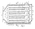
- the apparatus for indirect evaporative cooling of a gas contains a wantel 1 with an inlet nozzle 2 and two outlet nozzles 3 and 4.
- the inlet nozzle 2 is used to initiate a common gas flow, the z. B. is generated by a fan.
- the outlet port 3 serves to discharge the main flow.
- This nozzle has an adjustable slide 5 to reduce the passage cross section of the nozzle.
- the outlet connection 4 arranged in the upper part of the jacket serves to discharge the used auxiliary stream flowing in countercurrent to the main stream into the atmosphere.
- a wettable capillary-porous body 6 is accommodated in the jacket 1.
- Wet channels 7 and drying channels d are embodied in this body and are connected to one another on the side of the outlet connection 3.
- the drying tunnels formed by tubes 9 made of a moisture-impermeable material, which in the wettable capillary-pored body. 6 are introduced.
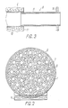
- the drying ducts can, however, be formed by a melted-off moisture-impermeable layer 10, as is shown in FIG. 3. Depending on the distance from the melted moisture-impermeable layer 10, the porosity increases up to a normally predetermined one.
- the projecting ends of the drying channels, which lie outside the body 6, are formed by tubes 11.
- the channels 7 and 8 can have different cross-sectional shapes, in particular a tubular shape.
- the wettable capillary-pored body 6 can, for. B. made of fibers, a powder or similar particles.
- the particles forming the body o can be connected to one another or not connected.
- the capillary-porous body 6 can be produced from a mesh-like, ceramic material, woven material, folded material, cardboard, worn fillings, a material sintered from fibers and powders, etc.
- the wettable capillary-porous body 6 must be permeable, i. that is, it does not have to have closed and sack pores and ensure that the wetting liquid is raised to a sufficiently large height under the action of the capillary forces, which determines the possibilities for the choice of the vertical dimensions of the apparatus. You have to take into account that when using unbound particles in the body there are 6 inserts, e.g. B. must be used from whetches of sufficient rigidity and with permeable walls.
- the capillary-pored body 6 shown in FIG. 1 is made of a metal fiber material that forms a rigid construction with end faces 12 and 13.
- the aforementioned can have any arbitrary shape. When changing the channel length, these surfaces can e.g. B. be formed step-like. If the capillary-porous body made of pourable particles, e.g. B. consists of sand, glass beads, etc., it is also expedient to use front grids that limit the body 6.
- the drying ducts 6 can be filled with a highly porous material (not shown in the figure), which consists of fibers and powders (with a minimal hydraulic (resistance). This intensifies the heat exchange in the ducts.
- the intensification of the heat exchange increases with an increase the thermal conductivity of the fibers and the powders from which this material is made, and in the case of an improvement in the contact of the material particles with one another and with the channel wall, the thermal conductivity of the porous material filling the dry channels being increased.
- An intensification of the heat exchange in the dry channels is also achieved by structuring the inner surface of the channels B according to any desired method.
- a tube plate 16 is provided in the jacket, in which the projecting ends of the tubes forming the drying channels are attached.
- the tube plate 16 is at a distance from the interface 12 of the wettable capillary pore 6 arranged, swipe the Ronrplatte 16 at the interface 12, a chamber 17 is formed for discharging the used auxiliary gas stream, which provides for pre-cooling of the common gas stream and prevents mixing of the common gas stream to be introduced with the used auxiliary gas stream.
- FIG. 3 shows a construction of the apparatus in which 16 tubes 11 are fastened in the tube plate 16, the projecting ends of the drying ducts form.
- each of the tubes 11 1 is located in the chamber 17, one end of each tube being fastened in the wettable capillary-pored body and the other end - in the tube plate 16.
- each of the projecting portions of the tubes 9, which are accommodated in the chamber 17, shown in FIGS. 1 and 3, and the length of each of the tubes 11 0.03 to 0.15 of the length of the associated drying duct o is, that is, it is preferable that the distance of the end face 12 of the wettable capillary parigen body 6 and the tube plate 16 from each other within the same limits. This area of the change in distance is the cheapest with regard to the effectiveness of the heat and mass transfer and the flow resistance of the used auxiliary gas flow.
- the present apparatus for indirect evaporative cooling of a gas has the following mode of operation.
- a fan (not shown in FIG.)
- a common gas flow is introduced into the drying ducts 8 through the inlet connection 2.
- By flowing the common stream through the sections of the tubes 9 located in the chamber 17, it is pre-cooled. This takes place thanks to the heat exchange with the auxiliary flow which is fed into the chamber 17 from the measuring channels 7.
- the precooled common gas stream is then cooled further as it flows through the drying channels 8 in the wettable capillary-pored body 6.
- the common stream is divided into two streams, uz a main stream and an auxiliary stream, an effective division of the common stream into the two streams mentioned is achieved by increasing the flow resistance on the side of the outlet connection 3 by means of the adjustable slide 5, by which Passage cross section of the nozzle 3 is reduced.
- the ratio of the main and the auxiliary gas flow to each other can be changed.
- the main flow is passed through the outlet nozzle 3 to the customer, while the auxiliary flow is introduced into the wet channels 7.
- the auxiliary flow flows in countercurrent to the common flow via these channels.
- the common gas stream is cooled in a temperature range to the dew point without changing the moisture content, while the auxiliary stream is heated (by taking heat from the main stream) and (by evaporation) the moisture from the wettable capillary-porous body 6 is moistened into this auxiliary stream), since at the outlet from the channels 7 the temperature of the auxiliary stream will be slightly below the temperature of the common stream to be introduced due to incomplete recuperation, while its relative air humidity is almost 100% bet
- the auxiliary stream with such characteristic data (before being discharged into the atmosphere) is fed into the chamber 17, in which a superficial heat exchange takes place with the common stream to be fed, the ambient temperature Has.
- the apparatus according to the invention ensures an improvement in operational and construction data by reducing water consumption and by creating more expedient conditions for the introduction and division of the heat-exchanging gas streams.
- the apparatus for indirect evaporative cooling of a gas can be used for air globes in air conditioning systems in social and production rooms, cabins and seating areas of vehicles.
Abstract
Der Apparat zur indirekten Verdampfungskühlung eines Gases enthält einen Mantel (1) mit einem Eintrittsstutzen (2) und Austrittsstutzen (3 und 4). Der Eintrittsstutzen (2) ist zur Einleitung eines gemeinsamen Gasstromes bestimmt. Der Austrittsstutzen (3) dient zur Ableitung des Hauptgasstromes und ist an der Seite angeordnet, wo der Hauptgasstrom dem Abnehmer zugeführt wird. Der Austrittsstutzen (4) ist zur Ableitung des Hilfsgasstromes in die Atmosphäre bestimmt und an der Seite des Eintrittsstutzens (2) angeordnet. Im Mantel (1) befindet sich ein benetzbarer kapillarponger Körper (6). Im Körper (6) sind Naß-kanäle (7) und Trockenkanäle (8) ausgeführt. die an der Seite des Austrittsstutzens (3) miteinander in Verbindung stehen. Dadurch wird es möglich, das Verhältnis der Flächeninhalte der Trocken- und Naßkanäle zueinander frei zu wählen, was zu einer bedeutenden Erhöhung der Wirksamkeit der Abkühlung führt.
Description
Die vorliegende Erfindun bezieht sick auf Wärmeaustauschapparate zur indirekten Verdampfungskühluns mit einem unmittelbaren Kontakt eines Kühlgases mit einer Flüssigkeit.The present invention relates to heat exchange apparatus for indirect evaporative cooling with direct contact of a cooling gas with a liquid.
In den ärmeaustausckapparaten des genannten Typs erfolgt die wärmeabführung voi Gasstrom, der als Hauptstrom bezeichnet wird, durch eine Trennwand des Apparates zu der Flüssigkeit, die durch Verdampfung im zweiten Gasstrom abgekühlt wird, welcher als Hilfsstrom bezeichnet wird. Als Kaltequelle dient die verdampfende Flüssigkeit, die sich entneder an der Wand des Wärmeaustauschapparates als Dünnfilm, oder in einem an dieser Wand befestigten kapillarperigen Stoff befindet. Der Mauptluftstrom fließt in von den Wänden aus einem fouchtigkeitsundurchlässigen Werkstoff gebildeten Kandlen, die als Trockenkanäle bezeichnet werden, während der Milsluftstrom in, z. B., von den Wänden mit einer dünnen Schicht aus einem kapillarporigen wassergesüttigten Stoff gebildeten Kanälen, die als Maβkanäle bezeichnet werden, flieβt.In the heat exchange apparatuses of the type mentioned, the heat is removed from the gas stream, which is referred to as the main stream, through a partition of the apparatus to the liquid, which is cooled by evaporation in the second gas stream, which is referred to as the auxiliary stream. The evaporating liquid, which is either on the wall of the heat exchange apparatus as a thin film, or in a capillary-permeable substance attached to this wall, serves as the cold source. The main air flow flows in channels formed by the walls from a moisture-impermeable material, which are referred to as drying ducts, while the air flow flows in, e.g. B., channels formed by the walls with a thin layer of a capillary-pore water-saturated substance, which are referred to as measuring channels, flows.
Es ist ein Wärmeaustauschapparat sur indirekten Verdampfungskühlung von Gasen (US, A, 2990696) bekannt, der einen Mantel mit zwei Eintrittsstutzen zur Einleitung von jeweils eines Hauptstromsund eines Hilfsstroms senkrecht zueinander und mit zwei Austrittsstutzen zur Ableitung jeweils des Hauptstroms und des Hilfsstroms enthält. Im Mantel sind Trocken- und Maβkanäle vorgesehen, die senkrecht zueinander verlaufen. Die Trockenkanäle sind für das Flieβen des Hauptstroµes vorγesehen. Die Naβkanäle dienen für das Fließen des Hilfsstromes und enthalten einen benetzbaren kapillarporigen Stoff. Dieser Stoff kann an den Wänden des Naßkanals angebracht werden, wodurch ein Fliessen des Hilfsstromes zwischen den Schichten des Stoffes gewährleistet wird, oder er kann in der Kanalmitte angebracht werden, wodurch ein Fließen des Hilfsstromes zwi-


Eine scleke Konstruktion gewährleistet eine Erhöhung der Wirksamkeitn der Abkühlung. Dadurch, daβ im Mantel ein benetzbarer kapillarporiger Mörper angebracht ist, ist die Möglichkeit einer unbegernzten gegenseitigen Anordnung von Trocken- und Maβksnälen sewie einer Ausführung der Kanäle unterschiedlicher Ausführungsform im Querschnitt, insbesendere einer Ausführung der Kanäle in Röhrenderm, ge-Trecken- und Malkanäle zueinsader in einem breiten Zereich gewählt werden. Dabei kann z. B. der Flächeninhalt der
Machstchend wird ein beversugtes Ausführungsbeispiel ler Erfindung angeführt, die anhand den beigefügten Zeichmungen weranschaulicht wird, in denen gleiche Teile mit gleichenBezugszeichen bezeichnet sind. Es zeigen.
- Fig. 1- in schenatischer Darstellung einen erfinlugsgemäβen Apparat zur indirekten Verdampfungskühlung eines Gases in Gehnitt;
- Fig. 2 - den Schnitt nach der Linie II-II in Fig. 1;
- Fig. 3 - eine weitere Äusführungsvariante des Trockenkanals des erfindungsgemäβen Apparates.
- Fig. 1- in schematic representation of a device according to the invention for indirect evaporative cooling of a gas in the cut;
- Fig. 2 - the section along the line II-II in Fig. 1;
- Fig. 3 - another embodiment variant of the drying tunnel of the apparatus according to the invention.
Wie es aus Fig. 1 zu ersehen ist, enthalt der Apparat zur indirekten Verdampfungskühlung eines Gases einen wantel 1 mit einem Eintrittsstutzen 2 und zwei Austrittsstutzen 3 und 4. Der Eintrittsstutzen 2 dient zur Einleitung eines gemeinsamen Gasstromes, der z. B. durch einen Lüfter erzeugt wird. Der Austrittsstutzen 3 dient zur Ableitung des Hauptstromes. Dieser Stutzen hat einen regelbaren Schieber 5 zur Verminderung des Durchgangsquerschnittes des Stutzens. Der im Oberteil des Mantels angeordnete Austrittsstutzen 4 dient zur Ableitung des im Gegenstrom zu dem Hauptstron fließenden verbrauchten Hilfsstromes in die Atmosphäre.As can be seen from Fig. 1, the apparatus for indirect evaporative cooling of a gas contains a
sie in Fig. 1 und 2 dargestellt, ist im Mantel 1 ein benetzbarer kapillarporiger Körper 6 untergebracht. In diesem Körper sind Naβkanäle 7 und Trockenkanäle d ausgeführt, die auf der Seite des Austrittsstutzens 3 miteinander in Verbindung stehen.1 and 2, a wettable capillary-
Im Ausführungs beispiel sind die Trockenkanäle ![]()
![]()
Dadurch, daβ im Mantel 1 der benetzbare käpillarporige Körper 6 angeordnet ist, kann das Vernaltnis der Wärmeaustauschflächen der frocken- und der Waβwanale zueinander geandert werden, weil die die Anordnung dieser Kanale relativ zueinander unbeschränkt ist sowie ihre Form geändert werden kann. Die Kanäle 7 und 8 können unterschiedliche Form des Querschnittes aurweissen, insbesondere eine Röhrenform haben.Because the wettable capillary-
Der benetzbare kapillarporige Körper 6 kann z. B. aus Fasern, einen Pulver oder ähnlichen Teilchen angefertigt werden. Die den Körper o bildenden Teilchen können miteinander verbunden oder nicht verbunden sein. Auf diese weise kann der kapillarporige Körper 6 aus einem netzartigen, Keramischen Stoff, Webstoff, Falzstoff, Karton, verschledenen Schüttungen, einem aus Fasern und Pulvern gesinterten Material usw. hergestellt werden. Dabei muβ der benetzbare kapillarporige Körper 6 durchlässig sein, d. h., er muβ keine geschlossenen und Sackporen aufweisen und die Hebung der Benetzungsflüssigkeit unter Einwirkung der Kapillarkräfte auf eine ausreichend gröβe Höhe gewährleisten, die die Möglichkeiten für die Wahl der Vertikalmaβe des Apparates bestimmt. Man muβ dabei berücksichtigen, daß bei Verwendung von nicht gebundenen Teilchen im Körper 6 Einsätze bestehend, z. B., aus Wetzen von ausreichender Steifigkeit und mit durchlässigen Wänden verwendet werden müssen.The wettable capillary-pored
Der in Fig. 1 dargestellte kapillarporige Körper 6 ist aus einem Metallfasermaterial hergestellt, das eine steife Konstruktion mit Stirnflächen 12 und 13 bildet. Zur eventuellen zusätzlichen Änderung des Verhältnisses der Flächeninhalte der Trocken- und der Naβkanäle 7 und Stirnflächen 8 zueinander können die genannten eine beliebige willkürliche Form haben. Bei einer Änderung der Kanallänge können diese Flächen z. B. stufenförmig ausgebildet werden. Wenn der kapillarporige Körper aus schüttbaren Teilchen, z . B. aus Sand, Glaskügelchen usw. besteht, ist es auβerdem zweckmäβig, Stirngitter zu verwenden, die den Körper 6 begrenzen.The capillary-
Die Trockenkanäle 6 können mit einen hochporösen material (in fig. nicht wiedergegeben) gefüllt werden, das aus Fasern und Pulvern (mit einem minimalen hydraulischen (iderstand) besteht. Dadurch wird der Wärmeaustausch in den Kanälen intensiviert. Die Intensivierung des Warmeaustausches nimmt bei einer Vergrößerung der Wärmeleitfähigkeit der Fasern und der Pulver, aus welchen dieses Material besteht, sowie im Falle einer Verbesserung der Kontakte der Materialteilchen miteinander und mit der Kanalwand zu, wobei die Wärmeleitfähigkeit des die TrockenKanäle füllenden porösen Materials erhöht wird. Eine den Intensivierung des Wärmeaustausches in den Trockenkanälen wird auch durch eine Strukturierung der Innenfläche der Kanäle B nach einem beliebigen Verfahren erzielt. Zu diesem Zweck können z. B., an der Innenfläche Hüten vorgesehen werden.The
Durch die Verwendung des kapillarporigen Körpers 6 wird die Beförderung der Flüssigkeit aus dem Mittel zur Zufuhrung der Benetzungsflüssigkeit zu der Verdampfungsfläche in den Maßkanälen 7 sichergestellt. Nie es in Fig. 1 oder 2 wiedergegeben ist, wird beim vorliegenden Ausführungsbeispiel der Erfindung als Mittel zur Zufuhrung der Flüssigkeit eine mit Wasser gefüllte Auffangschale 14 verwendet, in der der benetzbare kapillarporige Körper 6 mit seinem Unterteil untergebracht ist. Die genannte Auffangschale 14 weist eine Bohrung 15 für die Wasserzuführung in die Kapillare des Körpers 6 auf. Es ist klar, da.3
- * So der Originaltext. Richtig: Der Mantel 1 hat im Bereich . der
Anfangsschale 14Bohrungen 15 zur Wasserzuführung in die Kapillaren desKörpers 6.
anstelle der
- * So the original text. Correct: The
jacket 1 has in the area. theinitial shell 14holes 15 for supplying water to the capillaries of thebody 6.
instead of the
Wie es in Fig. 1 dargestellt ist, ist im Mantel eine Rohrplatte 16 vorgesehen, in der die vorstehenden Enden der die Trockenkanäle bildenden Rohre ![]()
![]()
![]()
![]()
Im Unterschied zu dem oben angeführten Ausführungsbeispiel der Erfindung ist in Fig. 3 eine Konstruktion des Apparates wiedergegeben, bei welcher in der Rohrplatte 16 Rohre 11 befestigt sind, die vorstehende Enden der Trockenkanäle ![]()
![]()
Den auf diesem Gebiet tätigen Fachleuten ist klar daß die Intensität der Vorkuhlung zunimmt, wenn die in der Kammer 17 angeordneten Abschnitte der Rohre 9 und die Rohre 11 mit einem benetzbaren kapillarporigen Material (in Fig. nicht wiedergegeben) uberzogen sind.It will be apparent to those skilled in the art that the pre-cooling intensity increases when the portions of tubes 9 and
Es ist zweckmäßig, daß die Länge jedes der in Fig. 1 und 3 gezeigten vorstehenden Abschnitte der Rohre 9, die in der Kammer 17 untergebracht sind, und die Länge jedes der Rohre 11 0,03 bis 0,15 der Länge des zugenörigen Trockenkanals o beträgt, d. h., es ist vorzuziehen, daß der Abstand der Stirnfläche 12 des benetzbaren kapillarparigen Körpers 6 und der Rohrplatte 16 voneinander in denselben Grenzen liegt. Dieser Bereich der Abstandsänderung ist mit Rücksicht auf die Wirksamkeit der Wärme-und Massenübertragung und auf den Strömungswiderstand des verbrauchten Hilfsgasstromes der günstigste. Berechnungen und experimentelle Daten zeigen, daß bei einer Größe des genannten Abstandes von unter 0,03 der Länge der Trockenkanäle ![]()
![]()
Der vorliegende Apparat zur indirekten Verdampfungskühlung eines Gases hat folgende Wirkungsweise. Mittels eines Lüfters (in Fig. nicht wiedergegeben) wird ein gemeinsamer Gasstrom durch den Eintrittsstutzen 2 in die Trockenkanäle 8 eingeleitet. Indem der gemeinsame Strom durch die in der Kammer 17 befindlichen Abschnitte der Rohre 9 fließt, wird er vorgekühlt. Dies erfolgt dank dem warmeaustauscn mit dem Hilfsstrom, der in die Kammer 17 aus den Maßkanälen 7 zugeführt wird. Der vorgekühlte gemeinsame Gasstrom wird dann bei seinem Fließen durch die Trockenkanäle 8 in dem benetzbaren kapillarporigen Körper 6 weiter gekuhlt. Hier steht die Außenfläche der Trockenkanäle 8 mit dem benetzbaren kapillarporigen Körper 6 in Berührung, der mit dem in der Auffangschale '14 befindlichen Wasser benetzt wird, das durch die Bohrung 15 in die Kapillare des Materials dieses Körpers gelangt. Am Austritt aus den Rohren 9 ist der gemeinsame Gasstrom auf eine im Bereich des Taupunktes liegende Temperatur ge- ![]()
![]()
Hier wird der gemeinsame Strom in zwei ströme, u. z. einen Hauptstrom und einen Hilfsstrom aufgeteilt, Eine wirksameAuf teilung des gemeinsamen Stromes in die zwei genannten Ströme wird durch eine Erhöhung des Strömungswiderstandes an der Seite des Austrittsstutzens 3 mittels des regelbaren Schiebers 5 erzielt, durcn den der Durchgangsquerschnitt des Stutzens 3 vermindert wird. Mit diesem Regelschieber 5 kann das Verhältnis des Haupt- und des Hilfsgasstromes zueinander geändert werden. Der Hauptstrom wird durch den Austrittsstutzen 3 zum Abnehmer geleitet, während der Hilfsstrom in die Naßkanäle 7 eingeleitet wird. Über diese Kanäle fließt der Hilfsstrom im Gegenstrom zu dem gemeinsamen Strom. Beim Fließen des Hilfsstromes in den Naßkanälen 7 findet ein oberflächlicher wärme- und Massenaustausch zwischen dem gemeinsamen Strom (der durch die Rohre 9 fließt und dem im Gegenstrom zu diesem (durch die Kanäle 7) fließenden Hilfsstrom durch die Wärme- und Wassenaustauschflächen der Rohre 9 und die Oberfläche des den Kanal 7 bildenden kapillarporigen Körper 6 statt. Im Ergebnis dieses Prozesses wird der gemeinsame Gasstrom in einem Temperaturbereich bis auf den Taupunkt ohne Anderung des Feuchtigkeitsgehaltes abgekühlt, Während der Hilfsstrom (durch eine Warmeentnahme von dem Hauptstrom) erwärmt und (durch eine Verdampfung der Feuchtigkeit aus dem benetzbaren kapillarporigen Körper 6 in diesen Hilfsstrom) befeuchtet wird. Da bei wird am Austritt aus den Kanälen 7 die Temperatur des Hilfsstromes infolge einer unvollständigen Rekuperation etwas unter der Temperatur des einzuleitenden gemeinsamen Stromes liegen, wänrend dessen relative Luftfeuchtigkeit fast 100% betragen wird. Diese Kenndaten des Hilfsstromes sind vom Standpunkt seines Abkühlungsvermögens aus von Bedeutung. Deshalb wird der Hilfsstrom mit solchen Kenndaten (bevor er in die Atmosphäre abgeleitet wird) in die Kammer 17 zugeführt, in der ein oberflachlicher Wärmeaustausch mit dem zuzuführenden gemeinsamen Strom stattfindet, der Umgebungstemperatur ![]()
![]()
Man muß darauf hinweisen, daß es bei dem erfindungsgemeßen Apparat möglich ist, eine Reihe von betriebstechnischen und Konstruktionsdaten wesentlich zu verbessern. So kann bei der Anderung der Fließrichtung des Hilfsstromes in der Kammer 17 um 90° und der Lenkung dieses Stromes nach oben zur A bf ührung in die Atmosphöre durch den Austrittsstutzen 4 eine wirksamere Abtrennung der Wassertropfen von dem Hilfsluftstrom gewährleistet werden. Dadurch wird es möglich, den Wasserdurchsatz im Wärmeaustauschapparat wesentlich zu reduzieren, was auch zu einer Erhöhung der Wirksamkeit der Abkühlung beiträgt.It must be pointed out that it is possible with the apparatus according to the invention to significantly improve a number of operational and design data. Thus, when the direction of flow of the auxiliary flow in the
Auf diese Weise wird durch die Verwendung des erfindungsgemäßen Apparates zur indirekten Verdampfungs a bkühlung eines Gases eine wesentliche Erhöhung der Wirksamkeit der Abkühlung gewährleistet, wobei eine bedeutende Temperaturerniedrigung des Hauptstromes ohne zusätzlichen Energieaufwand gesichert wird. Außerdem wird bei dem erfindungsgemäßen Apparat eine Verbesserung von betriebstechnischen und Konstruktionsdaten durch eine Verminderung des wasserverbrauches und durch die Schaffung von zweckmaßigeren Bedingungen für die Einleitung und die Einteilung der die Wärme austauschenden Gasströme gewährleistet.In this way, a significant increase in the effectiveness of the cooling is ensured by the use of the apparatus according to the invention for indirect evaporation cooling of a gas, a significant lowering of the temperature of the main stream being ensured without additional energy expenditure. In addition, the apparatus according to the invention ensures an improvement in operational and construction data by reducing water consumption and by creating more expedient conditions for the introduction and division of the heat-exchanging gas streams.
Der Apparat zurindirekten Verdampfungskuhlung eine Gases kann zur Luftkuglung in Klimaanlagen in sozial- und Prokuktionsräumen, Kabinen und Sitzraumen von Fahrzeugen Anwendung finden.The apparatus for indirect evaporative cooling of a gas can be used for air globes in air conditioning systems in social and production rooms, cabins and seating areas of vehicles.
Claims (2)
Applications Claiming Priority (1)
| Application Number | Priority Date | Filing Date | Title |
|---|---|---|---|
| PCT/SU1988/000169 WO1990002305A1 (en) | 1988-08-26 | 1988-08-26 | Indirect-evaporation gas cooling apparatus |
Publications (2)
| Publication Number | Publication Date |
|---|---|
| EP0389623A1 true EP0389623A1 (en) | 1990-10-03 |
| EP0389623A4 EP0389623A4 (en) | 1991-07-24 |
Family
ID=21617298
Family Applications (1)
| Application Number | Title | Priority Date | Filing Date |
|---|---|---|---|
| EP19890900368 Withdrawn EP0389623A4 (en) | 1988-08-26 | 1988-08-26 | Indirect-evaporation gas cooling apparatus |
Country Status (5)
| Country | Link |
|---|---|
| US (1) | US4976113A (en) |
| EP (1) | EP0389623A4 (en) |
| JP (1) | JPH03500923A (en) |
| FI (1) | FI902089A0 (en) |
| WO (1) | WO1990002305A1 (en) |
Families Citing this family (32)
| Publication number | Priority date | Publication date | Assignee | Title |
|---|---|---|---|---|
| DE19910441C1 (en) * | 1999-03-10 | 2000-06-21 | Fraunhofer Ges Forschung | Air humidifier comprises membrane contactor which has at least one tube membrane embedded in hydrophile porous body of ceramic, polymer or fabric preferably of porous thread material with hydrophilic surface |
| US5187946A (en) * | 1991-09-24 | 1993-02-23 | Yefim Rotenberg | Apparatus & Method for indirect evaporative cooling of a fluid |
| US5263337A (en) * | 1992-04-21 | 1993-11-23 | Mcmillan Robert B | Inertial parallel flow air conditioner |
| US5349829A (en) * | 1992-05-21 | 1994-09-27 | Aoc, Inc. | Method and apparatus for evaporatively cooling gases and/or fluids |
| US5315843A (en) * | 1992-08-13 | 1994-05-31 | Acma Limited | Evaporative air conditioner unit |
| US5996976A (en) * | 1993-07-13 | 1999-12-07 | Lynntech, Inc. | Gas humidification system using water permeable membranes |
| AUPM777294A0 (en) * | 1994-08-30 | 1994-09-22 | William Allen Trusts Pty Ltd | Spaced evaporative wicks within an air cooler |
| US5902384A (en) * | 1994-12-23 | 1999-05-11 | Alliedsignal Inc. | Wicking fiber with solid particulates for a high surface area odor removing filter and method of making |
| US5704966A (en) * | 1994-12-23 | 1998-01-06 | Alliedsignal Inc. | Method and apparatus for the continuous capturing and removal of gas molecules |
| US5951744A (en) * | 1994-12-23 | 1999-09-14 | Alliedsignal Inc. | Multicomponent depth odor control filter and method of manufacture |
| ES2138763T3 (en) * | 1994-12-23 | 2000-01-16 | Allied Signal Inc | A FILTRATION DEVICE USING ABSORPTION TO ELIMINATE CONTAMINANTS IN THE GASEOUS PHASE. |
| US5891221A (en) * | 1994-12-23 | 1999-04-06 | Alliedsignal Inc. | Chemical reagent package and method of operation effective at removing a wide range of odors |
| DE19623245C2 (en) * | 1996-05-30 | 1999-07-29 | Herbst Donald | Heat exchanger |
| US5692384A (en) * | 1996-07-15 | 1997-12-02 | Layton; Roy | Evaporative water cooler with heat exchanger in air stream |
| US6497107B2 (en) * | 2000-07-27 | 2002-12-24 | Idalex Technologies, Inc. | Method and apparatus of indirect-evaporation cooling |
| KR100409265B1 (en) * | 2001-01-17 | 2003-12-18 | 한국과학기술연구원 | Regenerative evaporative cooler |
| NL1021812C1 (en) * | 2002-04-26 | 2003-10-28 | Oxycell Holding Bv | Dew point cooler. |
| US20040061245A1 (en) * | 2002-08-05 | 2004-04-01 | Valeriy Maisotsenko | Indirect evaporative cooling mechanism |
| US7016472B2 (en) * | 2002-10-11 | 2006-03-21 | General Electric Company | X-ray tube window cooling apparatus |
| NL1022794C2 (en) | 2002-10-31 | 2004-09-06 | Oxycell Holding Bv | Method for manufacturing a heat exchanger, as well as heat exchanger obtained with the method. |
| US7093452B2 (en) * | 2004-03-24 | 2006-08-22 | Acma Limited | Air conditioner |
| US7181918B2 (en) * | 2004-03-25 | 2007-02-27 | Oxycell Holding B.V. | Vehicle cooler |
| NL1030538C1 (en) * | 2005-11-28 | 2007-05-30 | Eurocore Trading & Consultancy | Device for indirectly cooling an air stream through evaporation. |
| US20070138662A1 (en) * | 2005-12-19 | 2007-06-21 | Chiu Peng C | Closed evaporative cooling tower |
| JP5248629B2 (en) | 2008-01-25 | 2013-07-31 | アライアンス フォー サステイナブル エナジー リミテッド ライアビリティ カンパニー | Indirect evaporative cooler using liquid desiccant contained in membrane for dehumidification |
| KR101405618B1 (en) * | 2008-03-07 | 2014-06-10 | 엘지전자 주식회사 | Air conditioning system |
| US20100077783A1 (en) * | 2008-09-30 | 2010-04-01 | Bhatti Mohinder S | Solid oxide fuel cell assisted air conditioning system |
| JP3159566U (en) * | 2010-02-26 | 2010-05-27 | 株式会社アースクリーン東北 | Indirect vaporization cooling system |
| US20120273171A1 (en) * | 2011-04-27 | 2012-11-01 | Upadhya Girish K | Earthen evaporative heat exchanger |
| US9140471B2 (en) | 2013-03-13 | 2015-09-22 | Alliance For Sustainable Energy, Llc | Indirect evaporative coolers with enhanced heat transfer |
| US9140460B2 (en) | 2013-03-13 | 2015-09-22 | Alliance For Sustainable Energy, Llc | Control methods and systems for indirect evaporative coolers |
| US20180151324A1 (en) * | 2016-11-26 | 2018-05-31 | Varex Imaging Corporation | Heat sink for x-ray tube anode |
Citations (2)
| Publication number | Priority date | Publication date | Assignee | Title |
|---|---|---|---|---|
| US3100386A (en) * | 1959-06-29 | 1963-08-13 | Chausson Usines Sa | Evaporation heat exchanger |
| GB2060156A (en) * | 1979-09-26 | 1981-04-29 | Curtiss Wright Corp | A heat exchange fluid-cooling system and apparatus |
Family Cites Families (6)
| Publication number | Priority date | Publication date | Assignee | Title |
|---|---|---|---|---|
| US2960847A (en) * | 1957-09-04 | 1960-11-22 | Stewart Warner Corp | Heat exchanger |
| US2990696A (en) * | 1957-09-13 | 1961-07-04 | Stewart Warner Corp | Evaporative heat exchanger |
| SU407519A1 (en) * | 1972-05-26 | 1977-06-25 | Специальное Проектно-Конструкторское И Наладочное Бюро Министерства Тракторного И Сельскохозяйственного Машиностроения Ссср | Installation for indirect and evaporative air cooling |
| SU552494A1 (en) * | 1975-12-24 | 1977-03-30 | Одесский Технологический Институт Холодильной Промышленности | Device for indirectly evaporative gas cooling |
| SU620782A2 (en) * | 1976-06-07 | 1978-08-25 | Предприятие П/Я А-1665 | Heat-exchanging apparatus |
| SU659874A1 (en) * | 1978-03-10 | 1979-04-30 | Кондитерско-Булочный Комбинат "Черемушки" | Heat-exchanging apparatus |
-
1988
- 1988-08-26 WO PCT/SU1988/000169 patent/WO1990002305A1/en not_active Application Discontinuation
- 1988-08-26 EP EP19890900368 patent/EP0389623A4/en not_active Withdrawn
- 1988-08-26 JP JP1500095A patent/JPH03500923A/en active Pending
- 1988-08-26 US US07/477,893 patent/US4976113A/en not_active Expired - Fee Related
-
1990
- 1990-04-25 FI FI902089A patent/FI902089A0/en not_active Application Discontinuation
Patent Citations (2)
| Publication number | Priority date | Publication date | Assignee | Title |
|---|---|---|---|---|
| US3100386A (en) * | 1959-06-29 | 1963-08-13 | Chausson Usines Sa | Evaporation heat exchanger |
| GB2060156A (en) * | 1979-09-26 | 1981-04-29 | Curtiss Wright Corp | A heat exchange fluid-cooling system and apparatus |
Non-Patent Citations (1)
| Title |
|---|
| See also references of WO9002305A1 * |
Also Published As
| Publication number | Publication date |
|---|---|
| US4976113A (en) | 1990-12-11 |
| JPH03500923A (en) | 1991-02-28 |
| FI902089A0 (en) | 1990-04-25 |
| WO1990002305A1 (en) | 1990-03-08 |
| EP0389623A4 (en) | 1991-07-24 |
Similar Documents
| Publication | Publication Date | Title |
|---|---|---|
| EP0389623A1 (en) | Indirect-evaporation gas cooling apparatus | |
| DE2739627C2 (en) | Contact body for liquid and gas | |
| DE60109107T2 (en) | Plate heat exchanger | |
| DE102008034122B4 (en) | Heat exchanger, method of operating the heat exchanger and use of the heat exchanger in an air conditioning system | |
| EP0409984A1 (en) | Indirect-evaporation air cooling method | |
| DE3803534C1 (en) | ||
| DE2060178B2 (en) | Grid exchange packing for columns | |
| DD232539A5 (en) | GROUND FLOOR ELEMENTS FOR CONSTRUCTING A STONE PLATE | |
| DE3114195A1 (en) | MIXING DEVICE | |
| DE2623133C3 (en) | Filter for separating higher density material from lower density material | |
| DE102012211223A1 (en) | Micromachined frit and flow distribution devices for liquid chromatography | |
| DE4028806A1 (en) | Cryogenic microtome with reciprocating specimen carrier arm - sealed against cryogen leakage by fine air gap | |
| EP1430530B1 (en) | Heat exchanger | |
| DE3536316A1 (en) | Laminated oil cooler | |
| DE112014002085T5 (en) | Humidifier and humidifier having air conditioning | |
| DE2721197A1 (en) | DEVICE FOR ADJUSTING THE THICKNESS OF A LIQUID COATING OF A CONTINUOUS BELT | |
| DE10141525B4 (en) | Mass and heat exchange reactor | |
| EP0213298B1 (en) | Device for supporting and guiding layers | |
| DE102020210170A1 (en) | Capacitor element and method of manufacturing it | |
| EP3625511B1 (en) | Device for cooling, heating or transferring heat | |
| EP0290627B1 (en) | Heat pipe for cooling substances | |
| WO1999009594A1 (en) | Sintered heat sink | |
| DE2305710C3 (en) | Venturi washer | |
| DE202007012763U1 (en) | Moisturizing heating | |
| DE102008034123B4 (en) | Heat exchanger, method of operating the heat exchanger and use of the heat exchanger in an air conditioning system |
Legal Events
| Date | Code | Title | Description |
|---|---|---|---|
| PUAI | Public reference made under article 153(3) epc to a published international application that has entered the european phase |
Free format text: ORIGINAL CODE: 0009012 |
|
| 17P | Request for examination filed |
Effective date: 19900426 |
|
| AK | Designated contracting states |
Kind code of ref document: A1 Designated state(s): AT CH DE FR GB IT LI NL SE |
|
| A4 | Supplementary search report drawn up and despatched |
Effective date: 19910531 |
|
| AK | Designated contracting states |
Kind code of ref document: A4 Designated state(s): AT CH DE FR GB IT LI NL SE |
|
| 17Q | First examination report despatched |
Effective date: 19910828 |
|
| STAA | Information on the status of an ep patent application or granted ep patent |
Free format text: STATUS: THE APPLICATION IS DEEMED TO BE WITHDRAWN |
|
| 18D | Application deemed to be withdrawn |
Effective date: 19920108 |