EP0389097A2 - Photonic local/metropolitan area network - Google Patents
Photonic local/metropolitan area network Download PDFInfo
- Publication number
- EP0389097A2 EP0389097A2 EP90301571A EP90301571A EP0389097A2 EP 0389097 A2 EP0389097 A2 EP 0389097A2 EP 90301571 A EP90301571 A EP 90301571A EP 90301571 A EP90301571 A EP 90301571A EP 0389097 A2 EP0389097 A2 EP 0389097A2
- Authority
- EP
- European Patent Office
- Prior art keywords
- packet
- optical
- path
- network
- loop
- Prior art date
- Legal status (The legal status is an assumption and is not a legal conclusion. Google has not performed a legal analysis and makes no representation as to the accuracy of the status listed.)
- Granted
Links
Images


Classifications
-
- H—ELECTRICITY
- H04—ELECTRIC COMMUNICATION TECHNIQUE
- H04L—TRANSMISSION OF DIGITAL INFORMATION, e.g. TELEGRAPHIC COMMUNICATION
- H04L12/00—Data switching networks
- H04L12/28—Data switching networks characterised by path configuration, e.g. LAN [Local Area Networks] or WAN [Wide Area Networks]
-
- H—ELECTRICITY
- H04—ELECTRIC COMMUNICATION TECHNIQUE
- H04L—TRANSMISSION OF DIGITAL INFORMATION, e.g. TELEGRAPHIC COMMUNICATION
- H04L12/00—Data switching networks
- H04L12/28—Data switching networks characterised by path configuration, e.g. LAN [Local Area Networks] or WAN [Wide Area Networks]
- H04L12/2852—Metropolitan area networks
Definitions
- This invention relates generally to packet-switched optical communication systems for use in local and/or metropolitan area networks (LAN's or MAN's) and, more particularly, to such networks which are adapted to resolve collisions between advancing packets without buffering the colliding packets within the switching nodes.
- LAN local and/or metropolitan area networks
- MAN's metropolitan area networks
- Packet-switching technology has been advantageously applied to optical communication systems.
- packet-switched networks operating at low transmission speeds, the collisions between advancing packets are resolved by buffering the colliding packets until the output link becomes available.
- Such a scheme is commonly referred to as store-and-forward routing. Since large optical memories are expensive, today's solution for networks that use optical communication is to convert the optical signal to an electrical signal for appropriate buffering and queuing.
- the switching node of "hot-potato” topologies must have the same number of input and output links.
- a network commonly referred to as The Manhattan Street Network (MSN) utilizes the "hot potato” scheme.
- MSN The Manhattan Street Network
- the proposed invention also uses the "hot potato" routing.
- the proposed invention can be built on totally uncontained topologies.
- each path contains a reverse channel, the number of input and output paths to a switching node need not, necessarily, be equal.
- This invention refers to a packet-switched local or metropolitan area optical communications network in which collisions between two or more packets are resolved without local buffering in the switching node.
- a (logical) uni-directional link within a network is replaced by two optical links.
- One optical link which is referred to as the forward link, is capable of transmitting an optical signal in the direction of the original optical uni-directional link.
- the other link which can be referred to as the reverse link, is capable of transmitting an optical signal in the opposite direction.
- These links can be selectively configured to form either a direct path between the nodes (in which case only the forward link is used), or a "loop-back" path between the nodes (in which case both the forward and reverse are used to form a closed optical loop between the two nodes).
- the invention introduces a novel network architecture that is based on switching nodes which do not have local memory.
- the inventive network involves the use of optical fiber media to store packets in transit when a collision between two or more packets at a switching node is imminent.
- each uni-directional link in a conventional network is replaced by a fiber path composed of two links that carry packets in opposite directions. These two opposite-directed links can serve as a forward path or as a "loop-back" path.
- the two opposite-directed links are configured to form a loop on which a blocked packet will circulate until the required output loop at the arriving switching node becomes available.
- This invention avoids the need of large buffers within a switching node that needs to operate at high speeds. This becomes a serious problem as the transmission of the optical media increases.
- the invention is directed toward high performance communication systems, for example, distributed processing systems.
- Such high performance communication systems require the "low delay”, “multi-point”, “on-demand” delivery of large amounts of data.
- the "low-delay" characteristic of high performance communication systems refers to the rapidity with which data can be transmitted from one user of the system to another.
- certain operations - called atomic operations - must be performed without interruption if the integrity of the procedure is to be maintained.
- Exemplary of such operations is the withdrawal of funds from an account and the immediate debiting of said account to reflect such withdrawal.
- any interruption between such withdrawal and such debiting can endanger the integrity of the associated data bases.
- Low delay networks minimize the occurrence of such deleterious delays.
- the term "local area network” refers to a general-purpose network that can serve a wide variety of devices. Local area networks support minicomputers, mainframes, terminals, and other peripheral devices. In many cases, local area networks can carry not only data, but voice, video and graphics.
- One of the common types of a local area network topology which uses optical fiber is the star type of topology.
- a central switching element 10 is coupled to all of the nodes 12, 14, 16, 18, 20 of the network via, for example, optical fibers.
- a station wishing to transmit data sends its transmission to the central switching node 10 which forwards the transmission to the specified nodes by addressing data provided to node 10 by the source node.
- the Manhattan Street Network is based on a grid of alternatingly-directed paths of rows and columns normally referred to as streets and avenues.
- Various nodes 60, 62, 64, 66, 68, 70, 72, 74, 76, 78, 80, 82, 84, 86, 88, 90 exist on the corners of the streets and avenues.
- routing from a particular street and avenue to a destination is straightforward.
- any destination street and avenue destination can be found without asking directions, even when some roads are blocked.
- a Manhattan Street Network does not store-and-forward the data at intermediate nodes, and does require that the packets be immediately forwarded.
- Switching node 100 is coupled to switching nodes 102, 104, 106 via optical fiber paths 108, 110, 112.
- Appropriate hosts 101, 103, 105, 107, 109, 111, 113, 115, 117 are associated with each node.
- Optical fiber paths 108, 110 and 112 can be used to transmit a packet from node 100 directly to nodes 102, 104 and 106 respectively.
- the optical fiber paths can store the optical packet being transmitted by causing it to circulate around the optical path 108, 110, and/or 112. The number of times a packet circulates can be limited by a loop-count field in the header portion of the packet.
- a second optical fiber path is required from node 100 to each of the other nodes 102, 104 and 106.
- double-sided arrows are assigned to the optical fiber paths to indicate that there are two separate paths for serving traffic in opposite directions.
- Each optical fiber path, or loop 108, 110, 112 is a bi-directional channel which serves unidirectional network traffic.
- two loops are required. In a different configuration, a single loop can serve traffic in both directions.
- FIG. 4 there is illustrated a format of a packet which can be used to specify the source route as a series of hop-selects.
- Each hop-select field indicates the output link on which the packet is to be forwarded for that hop.
- the first non-zero hop-select field in the packet is examined to determine the next output link for the packet. If that output path is available for transmission of a new packet, the hop-select field is zeroed and the packet is immediately routed to the available output link.
- the packet When a packet is blocked because the output path that was selected is unavailable at the packet's arrival time, the packet is routed back to the previous switching node on the return portion of the path that the packet arrived on. Upon its arrival at the previous switching node, the return packet is again sent to arrive at the blocking switching node one round-trip time after it first arrives at the node.
- the optical fiber path effectively provides short-term storage of the optical packet and causes the packet to reappear at the blocking switching node a short time later.
- the loopcount field of a packet header is decremented and examined each time a packet is returned. If the loopcount reaches zero, the packet is removed from the network to prevent a packet from indefinitely looping within the network because of a failure or load condition.
- This invention does not require memory in the switching node of the size and speed which is required to store all blocked packets, such as would be required for a conventional store-and-forward design. Additionally, the loop-back technique here disclosed exerts back pressure on the link over which the packet was received because each return packet reduces the availability of the path for receiving and forwarding new packets. In an extreme case, the back pressure can extend back from the point of contention to one or more of the packet sources. Besides alerting the packet sources of congestion, the back pressure provides fast feedback to the source routing mechanism to enable it to react more quickly to network load and topological changes.
- Each optical fiber path 108, 110, 112 comprises two optical links which, when joined end to end forms a loop and together has a total length which is equal to or larger than the length of the packet being transmitted, or to the maximum packet size if variable length packets are used.
- Switches that are used to reconfigure the optical paths are commercial products of, for example, BT&D Technologies, having offices in the United States and in England, and Crystal Technology, Inc., having offices in Palo Alto, California.
- two or more loops can be physically concatenated by a simple switching node with two input and two output loops. If the internodel distance is less than the size of the loop, the excessive length of the loop can be compactly stored. For example, an optical fiber loop located between nodes 100 meters apart can store a packet of 300 bits when the link operates at 1Gbps with a single color transmission.
- each optical path is comprised of two optical links which can be selectively configured to form a straight-through transmission path for an optical packet or a loop-back path for the optical packet to controllably selectively delay its advance.
- Each input path includes a packet detector circuit 120 and a switching delay 122.
- the packet detector circuit scans the input path for syncs. Upon detection of a sync, the packet detector generates a new-packet signal and reports a packet arrival to a Control circuit 121.
- Switching delay 122 which is coupled to report header information to Control circuits 121, can comprise a length of fiber which is long enough to contain the packet header and the number of bits which correspond to the time the control logic requires to do the actual switching.
- Each output path 118 includes a packet detector circuit 124 that scans the output path for a returned packet and is coupled to report this information to Control circuits 121. Upon detection of a returned packet, a returned-packet signal is generated. A loop is considered to be free if it does not contain a packet or any part of a packet.
- the Control circuit can uniquely determine the status of a loop using the returned-packet signal and a timer that can be set for a packet length. (other implementations are also possible.)
- the switching nodes that switch a packet from an input loop 116 to an output loop 118 can be implemented in a switching matrix configuration. However, in those instances where there are a large number of inputs/outputs, an alternate switch architecture, such as a variation of Banyan network, can be used.
- the availability of the output loop is checked.
- An output loop is available if no active connection of any other loop to this loop currently exists and the loop is not occupied by a returned packet.
- the condition that a loop is not occupied by a returned packet can be determined by the timer that is triggered by the sync of every transmitted and/or returned packet. If the output loop is available, the packet is clocked from its input loop onto the output loop by closing switches 126, 128 as illustrated. If, on the other hand, the output loop is busy, the packet is blocked, and it is returned by being clocked out on the same input loop it came in on. This is accomplished by positioning switch 126 as shown by the dotted arrow.
- the successful packet will be the one with the higher priority (if the priority field is implemented in the packet structure) or the one that is chosen randomly in the case of equal priorities.
- Each other packet or packets are clocked out on their loops.
- the input loop terminates at another node and at this other node the loop is referred to as the output loop.
- a blocked packet upon arriving at the other node, sets the timer to indicate that the loop is busy and is clocked out to arrive at the blocking node one round trip later.
- the switching node of FIG. 5 can be implemented as an interconnection of a number of photonic components.
- local I/O packets can be handled in a manner similar to the way that the forwarded packets are handled.
- the local delay line 130 of a local fiber optical loop having two optical links can have a length that is equal to that of the packet size. on the same principle as an insert register in LAN's.
- a new message from the local host can be input to the local loop and circulate in the local loop until it is inserted into the network.
- the schematic of FIG. 6 is similar to that of FIG. 5 with the addition of a local loop and the necessary switches.
- a collision between two packets can be resolved in optical network topologies by replacing each of the various logical links with an optical loop having two substantially parallel optical links which can be selectively configured to form either a direct straight throughput or loop-back path.
- FIG. 7 illustrates a Star-of-Star type of network topology having central switching elements 150, 152, 154, 156, 158 interconnected via optical fiber paths, and nodes 160, 162, 164, 166 of each cluster coupled to an associated central switching element via an optical fiber path having two optical links which can be selectively configured to form either a direct straight through path or a loop-back path.
- collisions of optical packets in network topologies are resolved by using selectively configurable optical fiber paths to couple together the various nodes.
- An optical fiber path when configured to form a loop-back, resolves collisions by delaying the advance of an optical packet.
- the loop-back path effectively functions as a storage medium for the packet.
- a colliding packet can be recirculated around a loop until a preceding packet has been cleared.
Abstract
Description
- This invention relates generally to packet-switched optical communication systems for use in local and/or metropolitan area networks (LAN's or MAN's) and, more particularly, to such networks which are adapted to resolve collisions between advancing packets without buffering the colliding packets within the switching nodes.
- Packet-switching technology has been advantageously applied to optical communication systems. In packet-switched networks operating at low transmission speeds, the collisions between advancing packets are resolved by buffering the colliding packets until the output link becomes available. Such a scheme is commonly referred to as store-and-forward routing. Since large optical memories are expensive, today's solution for networks that use optical communication is to convert the optical signal to an electrical signal for appropriate buffering and queuing.
- While the buffering and queuing techniques have met with some success for optical communication systems, such techniques become commercially impractical when data transmission speeds increase into the Gbps range. This is because of the optical-to-electrical conversion required. Some alternatives to the store-and-forward scheme have been proposed. One such alternative, commonly referred to as "hot-potato" routing, assumes no buffers in the switching nodes. Whenever two or more packets are about to collide, one packet is forwarded to the desired output and other packet or packets are forwarded to another output, which may not be the best route to the packet destination node.
- In general, the switching node of "hot-potato" topologies must have the same number of input and output links. A network, commonly referred to as The Manhattan Street Network (MSN) utilizes the "hot potato" scheme. Unfortunately, a Manhattan Street Network requires a very inflexible grid type of topology. While such a topology may be suitable for some networks, clearly it is not the best choice in many other cases, especially for larger networks.
- The proposed invention also uses the "hot potato" routing. However, as opposed to MSN, for example, the proposed invention can be built on totally uncontained topologies. Moreover, because each path contains a reverse channel, the number of input and output paths to a switching node need not, necessarily, be equal.
- A "hot-potato" switching scheme by the "loop-back" technique, as used in this invention is described in "Blazenet": A Photonic Implemental Wide-Area Network," Department of Computer Science, Stanford University, Technical report No. STAN-CS-87-1185, October 1987. The proposed invention deals with the local/metropolitan area networks, as opposed to wide-area networks in "Blazenet".
- This invention refers to a packet-switched local or metropolitan area optical communications network in which collisions between two or more packets are resolved without local buffering in the switching node.
- In this invention, a (logical) uni-directional link within a network is replaced by two optical links. One optical link, which is referred to as the forward link, is capable of transmitting an optical signal in the direction of the original optical uni-directional link. The other link, which can be referred to as the reverse link, is capable of transmitting an optical signal in the opposite direction. These links can be selectively configured to form either a direct path between the nodes (in which case only the forward link is used), or a "loop-back" path between the nodes (in which case both the forward and reverse are used to form a closed optical loop between the two nodes).
- Prior to advancing a packet through a node to the next occurring node in the inventive system, a determination is made as to whether or not the optical loop which connects this node to that next node is occupied with a packet. If the optical loop is not occupied, the packet is advanced along the forward optical link to the next node. If the optical fiber loop is occupied, then the reverse optical link connected to the previous node is rapidly reconfigured to form a "loop-back" path, and the packet is sent back to the previous node via this "loop-back" path. The packet may be "recirculated" in this "loop-back" path until the optical loop to the next node becomes available.
- In the drawing,
- FIG. 1 is a schematic representation of a prior art local area network having a star topology;
- FIG. 2 is a schematic representation of a prior art local area network commonly referred to as a Manhattan Street Network;
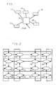
- FIG. 3 is a schematic representation of four nodes coupled together via optical fiber paths in accordance with the principles of the invention;
- FIG. 4 is a schematic representation of a source routed packet format which can be used to route a packet through a network in accordance with the principles of the invention;
- FIG. 5 is a schematic representation of an optical network in accordance with the principles of the invention;
- FIG. 6 is a schematic of an additional input for coupling traffic from a local source to the network of FIG. 5; and
- FIG. 7 is a schematic representation of a Star-of-Star network in accordance with the principles of the invention.
- The invention introduces a novel network architecture that is based on switching nodes which do not have local memory. The inventive network involves the use of optical fiber media to store packets in transit when a collision between two or more packets at a switching node is imminent. According to the invention, each uni-directional link in a conventional network is replaced by a fiber path composed of two links that carry packets in opposite directions. These two opposite-directed links can serve as a forward path or as a "loop-back" path. In the later case, the two opposite-directed links are configured to form a loop on which a blocked packet will circulate until the required output loop at the arriving switching node becomes available. This invention avoids the need of large buffers within a switching node that needs to operate at high speeds. This becomes a serious problem as the transmission of the optical media increases.
- The invention is directed toward high performance communication systems, for example, distributed processing systems. Such high performance communication systems require the "low delay", "multi-point", "on-demand" delivery of large amounts of data.
- The "low-delay" characteristic of high performance communication systems refers to the rapidity with which data can be transmitted from one user of the system to another. For example, certain operations - called atomic operations - must be performed without interruption if the integrity of the procedure is to be maintained. Exemplary of such operations is the withdrawal of funds from an account and the immediate debiting of said account to reflect such withdrawal. Clearly, any interruption between such withdrawal and such debiting can endanger the integrity of the associated data bases. Low delay networks minimize the occurrence of such deleterious delays. The term "local area network" refers to a general-purpose network that can serve a wide variety of devices. Local area networks support minicomputers, mainframes, terminals, and other peripheral devices. In many cases, local area networks can carry not only data, but voice, video and graphics.
- One of the common types of a local area network topology which uses optical fiber is the star type of topology.
- Referring to FIG. 1, there is illustrated a Star network. A
central switching element 10 is coupled to all of thenodes central switching node 10 which forwards the transmission to the specified nodes by addressing data provided tonode 10 by the source node. - Clearly, as the number of users for the network increases, the throughput per user decreases, at least linearly. To help avoid this problem, mesh networks were developed. One such network is the Manhattan Street Network illustrated in FIG. 2. The Manhattan Street Network is based on a grid of alternatingly-directed paths of rows and columns normally referred to as streets and avenues.
Various nodes - An example of a Star type of network topology, in accordance with the principles of this invention, having four nodes is illustrated in FIG. 3.
Switching node 100 is coupled to switchingnodes optical fiber paths Appropriate hosts Optical fiber paths node 100 directly tonodes optical path - To enable the network of FIG. 3 to carry traffic in two directions, a second optical fiber path is required from
node 100 to each of theother nodes loop - To advance packets, fast switching and simple switching logic at each switching node can be implemented with source routing. Referring to FIG. 4, there is illustrated a format of a packet which can be used to specify the source route as a series of hop-selects. Each hop-select field indicates the output link on which the packet is to be forwarded for that hop. When a packet arrives at a switching node, the first non-zero hop-select field in the packet is examined to determine the next output link for the packet. If that output path is available for transmission of a new packet, the hop-select field is zeroed and the packet is immediately routed to the available output link.
- When a packet is blocked because the output path that was selected is unavailable at the packet's arrival time, the packet is routed back to the previous switching node on the return portion of the path that the packet arrived on. Upon its arrival at the previous switching node, the return packet is again sent to arrive at the blocking switching node one round-trip time after it first arrives at the node. Thus, the optical fiber path effectively provides short-term storage of the optical packet and causes the packet to reappear at the blocking switching node a short time later. The loopcount field of a packet header is decremented and examined each time a packet is returned. If the loopcount reaches zero, the packet is removed from the network to prevent a packet from indefinitely looping within the network because of a failure or load condition.
- This invention does not require memory in the switching node of the size and speed which is required to store all blocked packets, such as would be required for a conventional store-and-forward design. Additionally, the loop-back technique here disclosed exerts back pressure on the link over which the packet was received because each return packet reduces the availability of the path for receiving and forwarding new packets. In an extreme case, the back pressure can extend back from the point of contention to one or more of the packet sources. Besides alerting the packet sources of congestion, the back pressure provides fast feedback to the source routing mechanism to enable it to react more quickly to network load and topological changes.
- The simple logic required for hop selection increases its photonic implementation feasibility and makes the switching at gigabit data rate possible.
- Each
optical fiber path - If the distance between nodes exceeds the length which corresponds to the packet size, two or more loops can be physically concatenated by a simple switching node with two input and two output loops. If the internodel distance is less than the size of the loop, the excessive length of the loop can be compactly stored. For example, an optical fiber loop located between
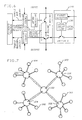
nodes 100 meters apart can store a packet of 300 bits when the link operates at 1Gbps with a single color transmission. - Referring to FIG.5, there is illustrated a schematic of structure in accordance with the principles of the invention. For simplicity, only two switching nodes each having one input path 116 and one
output path 118 are shown. As noted previously, each optical path is comprised of two optical links which can be selectively configured to form a straight-through transmission path for an optical packet or a loop-back path for the optical packet to controllably selectively delay its advance. - Each input path includes a
packet detector circuit 120 and a switchingdelay 122. The packet detector circuit scans the input path for syncs. Upon detection of a sync, the packet detector generates a new-packet signal and reports a packet arrival to aControl circuit 121.Switching delay 122, which is coupled to report header information toControl circuits 121, can comprise a length of fiber which is long enough to contain the packet header and the number of bits which correspond to the time the control logic requires to do the actual switching. - Each
output path 118 includes apacket detector circuit 124 that scans the output path for a returned packet and is coupled to report this information toControl circuits 121. Upon detection of a returned packet, a returned-packet signal is generated. A loop is considered to be free if it does not contain a packet or any part of a packet. The Control circuit can uniquely determine the status of a loop using the returned-packet signal and a timer that can be set for a packet length. (other implementations are also possible.) - The switching nodes that switch a packet from an input loop 116 to an
output loop 118 can be implemented in a switching matrix configuration. However, in those instances where there are a large number of inputs/outputs, an alternate switch architecture, such as a variation of Banyan network, can be used. - When a packet is to be forwarded from an input loop to an output loop, the availability of the output loop is checked. An output loop is available if no active connection of any other loop to this loop currently exists and the loop is not occupied by a returned packet. The condition that a loop is not occupied by a returned packet can be determined by the timer that is triggered by the sync of every transmitted and/or returned packet. If the output loop is available, the packet is clocked from its input loop onto the output loop by closing
switches switch 126 as shown by the dotted arrow. If more than one packet attempts to enter a specific output loop, only one packet will succeed. The successful packet will be the one with the higher priority (if the priority field is implemented in the packet structure) or the one that is chosen randomly in the case of equal priorities. Each other packet or packets are clocked out on their loops. The input loop terminates at another node and at this other node the loop is referred to as the output loop. A blocked packet, upon arriving at the other node, sets the timer to indicate that the loop is busy and is clocked out to arrive at the blocking node one round trip later. - The switching node of FIG. 5 can be implemented as an interconnection of a number of photonic components.
- Referring to FIG. 6, local I/O packets can be handled in a manner similar to the way that the forwarded packets are handled. The
local delay line 130 of a local fiber optical loop having two optical links can have a length that is equal to that of the packet size. on the same principle as an insert register in LAN's. When the current message is inserted into the network, and empties the local loop, a new message from the local host can be input to the local loop and circulate in the local loop until it is inserted into the network. The schematic of FIG. 6 is similar to that of FIG. 5 with the addition of a local loop and the necessary switches. - In accordance with the principles of this invention, a collision between two packets can be resolved in optical network topologies by replacing each of the various logical links with an optical loop having two substantially parallel optical links which can be selectively configured to form either a direct straight throughput or loop-back path.
- FIG. 7 illustrates a Star-of-Star type of network topology having
central switching elements nodes - Thus, collisions of optical packets in network topologies are resolved by using selectively configurable optical fiber paths to couple together the various nodes. An optical fiber path, when configured to form a loop-back, resolves collisions by delaying the advance of an optical packet. By recirculating a packet through the loop-back path, the loop-back path effectively functions as a storage medium for the packet. With appropriate switching control, a colliding packet can be recirculated around a loop until a preceding packet has been cleared.
Claims (12)
Applications Claiming Priority (2)
| Application Number | Priority Date | Filing Date | Title |
|---|---|---|---|
| US314724 | 1989-02-23 | ||
| US07/314,724 US4970717A (en) | 1989-02-23 | 1989-02-23 | Photonic local/metropolitan area network |
Publications (3)
| Publication Number | Publication Date |
|---|---|
| EP0389097A2 true EP0389097A2 (en) | 1990-09-26 |
| EP0389097A3 EP0389097A3 (en) | 1991-12-04 |
| EP0389097B1 EP0389097B1 (en) | 1995-10-04 |
Family
ID=23221168
Family Applications (1)
| Application Number | Title | Priority Date | Filing Date |
|---|---|---|---|
| EP90301571A Expired - Lifetime EP0389097B1 (en) | 1989-02-23 | 1990-02-14 | Photonic local/metropolitan area network |
Country Status (8)
| Country | Link |
|---|---|
| US (1) | US4970717A (en) |
| EP (1) | EP0389097B1 (en) |
| JP (1) | JP2523201B2 (en) |
| KR (1) | KR900013738A (en) |
| CA (1) | CA2005997C (en) |
| DE (1) | DE69022758T2 (en) |
| ES (1) | ES2078940T3 (en) |
| HK (1) | HK33596A (en) |
Cited By (1)
| Publication number | Priority date | Publication date | Assignee | Title |
|---|---|---|---|---|
| GB2321563A (en) * | 1997-01-24 | 1998-07-29 | Plessey Telecomm | Burst mode wavelength controller |
Families Citing this family (13)
| Publication number | Priority date | Publication date | Assignee | Title |
|---|---|---|---|---|
| US5138615A (en) * | 1989-06-22 | 1992-08-11 | Digital Equipment Corporation | Reconfiguration system and method for high-speed mesh connected local area network |
| US5421030A (en) * | 1991-09-17 | 1995-05-30 | Com21, Inc. | Communications system and method for bi-directional communications between an upstream control facility and downstream user terminals |
| US5341415A (en) * | 1992-09-22 | 1994-08-23 | Paul Baran | Method and apparatus for sharing of common in-house wiring to permit multiple telephone carriers to serve the same customer |
| CA2144953A1 (en) * | 1992-09-29 | 1994-04-14 | Paul Baran | Cell based wide area network alternative access telephone and data system |
| US5425027A (en) * | 1993-01-04 | 1995-06-13 | Com21, Inc. | Wide area fiber and TV cable fast packet cell network |
| AU753148B2 (en) * | 1997-09-17 | 2002-10-10 | British Telecommunications Public Limited Company | Communications network |
| US6128113A (en) * | 1998-03-04 | 2000-10-03 | Dynamics Research Corporation | Transparent optical communications switch |
| US6748451B2 (en) | 1998-05-26 | 2004-06-08 | Dow Global Technologies Inc. | Distributed computing environment using real-time scheduling logic and time deterministic architecture |
| US6567429B1 (en) | 1998-06-02 | 2003-05-20 | Dynamics Research Corporation | Wide area multi-service broadband network |
| DE19940565C1 (en) * | 1999-08-26 | 2001-02-01 | Siemens Ag | Connection path control for optic data packet transmission |
| US7145704B1 (en) | 2003-11-25 | 2006-12-05 | Cheetah Omni, Llc | Optical logic gate based optical router |
| US7308002B2 (en) * | 2003-11-24 | 2007-12-11 | Intergrated System Solution Corp. | Packet type arbitrator in WLAN and corresponding arbitrating method |
| US7245831B2 (en) * | 2004-10-04 | 2007-07-17 | Board Of Supervisors Of Louisiana State University And Agricultural And Mechanical College | Optical packet switching |
Citations (3)
| Publication number | Priority date | Publication date | Assignee | Title |
|---|---|---|---|---|
| EP0226417A1 (en) * | 1985-12-06 | 1987-06-24 | BRITISH TELECOMMUNICATIONS public limited company | Operating a multiple-access optical network |
| US4710914A (en) * | 1985-08-29 | 1987-12-01 | Compagnie General D'electricite | Optical fiber telecommunication device |
| EP0269376A2 (en) * | 1986-11-24 | 1988-06-01 | Westinghouse Electric Corporation | A token passing scheme for a predetermined configuration local area network |
Family Cites Families (5)
| Publication number | Priority date | Publication date | Assignee | Title |
|---|---|---|---|---|
| US4674085A (en) * | 1985-03-21 | 1987-06-16 | American Telephone And Telegraph Co. | Local area network |
| US4701907C1 (en) * | 1986-02-03 | 2002-08-27 | Collins Mary | Dynamically reconfigurable time-space-time digital switch and network |
| US4829512A (en) * | 1986-08-26 | 1989-05-09 | Nec Corporation | Loop-back control apparatus for a loop network having duplicate optical fiber transmission lines |
| US4847837A (en) * | 1986-11-07 | 1989-07-11 | The United States Of America As Represented By The Administrator Of The National Aeronautics And Space Administration | Local area network with fault-checking, priorities and redundant backup |
| US4835763A (en) * | 1988-02-04 | 1989-05-30 | Bell Communications Research, Inc. | Survivable ring network |
-
1989
- 1989-02-23 US US07/314,724 patent/US4970717A/en not_active Expired - Lifetime
- 1989-12-19 CA CA002005997A patent/CA2005997C/en not_active Expired - Fee Related
-
1990
- 1990-02-14 EP EP90301571A patent/EP0389097B1/en not_active Expired - Lifetime
- 1990-02-14 ES ES90301571T patent/ES2078940T3/en not_active Expired - Lifetime
- 1990-02-14 DE DE69022758T patent/DE69022758T2/en not_active Expired - Lifetime
- 1990-02-20 KR KR1019900002030A patent/KR900013738A/en not_active Application Discontinuation
- 1990-02-22 JP JP2039902A patent/JP2523201B2/en not_active Expired - Lifetime
-
1996
- 1996-02-29 HK HK33596A patent/HK33596A/en not_active IP Right Cessation
Patent Citations (3)
| Publication number | Priority date | Publication date | Assignee | Title |
|---|---|---|---|---|
| US4710914A (en) * | 1985-08-29 | 1987-12-01 | Compagnie General D'electricite | Optical fiber telecommunication device |
| EP0226417A1 (en) * | 1985-12-06 | 1987-06-24 | BRITISH TELECOMMUNICATIONS public limited company | Operating a multiple-access optical network |
| EP0269376A2 (en) * | 1986-11-24 | 1988-06-01 | Westinghouse Electric Corporation | A token passing scheme for a predetermined configuration local area network |
Non-Patent Citations (1)
| Title |
|---|
| DEPARTEMENT OF COMPUTER SCIENCE, STANFORD UNIVERSITY, TECHNICAL REPORT, No. STAN-CS-87-1185, October 1987, Stanford, USA Z. HAAS et al. " Blazenet: A Photonic Implementable Wide- Area Network" pages 1-21 * |
Cited By (3)
| Publication number | Priority date | Publication date | Assignee | Title |
|---|---|---|---|---|
| GB2321563A (en) * | 1997-01-24 | 1998-07-29 | Plessey Telecomm | Burst mode wavelength controller |
| GB2321563B (en) * | 1997-01-24 | 1999-04-21 | Plessey Telecomm | Burst mode wavelength manager |
| AU727021B2 (en) * | 1997-01-24 | 2000-11-30 | Marconi Communications Limited | Burst mode wavelength manager |
Also Published As
| Publication number | Publication date |
|---|---|
| EP0389097A3 (en) | 1991-12-04 |
| DE69022758D1 (en) | 1995-11-09 |
| HK33596A (en) | 1996-03-08 |
| CA2005997A1 (en) | 1990-08-23 |
| EP0389097B1 (en) | 1995-10-04 |
| JPH02248133A (en) | 1990-10-03 |
| US4970717A (en) | 1990-11-13 |
| KR900013738A (en) | 1990-09-06 |
| JP2523201B2 (en) | 1996-08-07 |
| CA2005997C (en) | 1995-02-14 |
| DE69022758T2 (en) | 1996-03-14 |
| ES2078940T3 (en) | 1996-01-01 |
Similar Documents
| Publication | Publication Date | Title |
|---|---|---|
| EP0724798B1 (en) | Selective congestion control mechanism for information networks | |
| US5901140A (en) | Selective congestion control mechanism for information networks | |
| US6967926B1 (en) | Method and apparatus for using barrier phases to limit packet disorder in a packet switching system | |
| US4970717A (en) | Photonic local/metropolitan area network | |
| US6907041B1 (en) | Communications interconnection network with distributed resequencing | |
| EP1317825B1 (en) | System and method for controlling the multicast traffic of a data packet switch | |
| JP2963316B2 (en) | Packet distribution network | |
| EP0658027A2 (en) | Channel sharing and memory sharing in a packet switching system | |
| JP2918772B2 (en) | Packet switching arrangement | |
| JP4146080B2 (en) | Communication network | |
| KR19980064825A (en) | Distributed buffering system of A.T.M switch | |
| EP0590865B1 (en) | Multistage growable optical packet switching arrangement with bypass | |
| US5285449A (en) | Protocol for hybrid local area networks | |
| AU719413B2 (en) | Logical multicast from a switch configured for spatial multicast | |
| CA2371037C (en) | A node and method for the removal of expired packets from a communication network | |
| WO2000004741A1 (en) | A reliable and robust atm-switch | |
| Chlamtac et al. | Scalable WDM network architecture based on photonic slot routing and switched delay lines | |
| Karol et al. | Performance of the PAC optical packet network | |
| Haas et al. | Blazenet: A packet-switched wide-area network with photonic data path | |
| Wong et al. | Pipeline banyan-a parallel fast packet switch architecture | |
| US7321558B2 (en) | Method and apparatus in a computer network | |
| Haas | Loop concatenation and loop replication to improve Blazelan performance | |
| Haas | BLAZELAN: A photonic local-area network for distributed and parallel processing | |
| Haas et al. | Blazenet: A Phototonic Implementable Wide-area Network | |
| Smit et al. | Multicast and Broadcast in the Rattlesnake ATM Switch. |
Legal Events
| Date | Code | Title | Description |
|---|---|---|---|
| PUAI | Public reference made under article 153(3) epc to a published international application that has entered the european phase |
Free format text: ORIGINAL CODE: 0009012 |
|
| AK | Designated contracting states |
Kind code of ref document: A2 Designated state(s): DE ES FR GB IT NL |
|
| PUAL | Search report despatched |
Free format text: ORIGINAL CODE: 0009013 |
|
| AK | Designated contracting states |
Kind code of ref document: A3 Designated state(s): DE ES FR GB IT NL |
|
| 17P | Request for examination filed |
Effective date: 19911105 |
|
| 17Q | First examination report despatched |
Effective date: 19931018 |
|
| RAP3 | Party data changed (applicant data changed or rights of an application transferred) |
Owner name: AT&T CORP. |
|
| GRAA | (expected) grant |
Free format text: ORIGINAL CODE: 0009210 |
|
| AK | Designated contracting states |
Kind code of ref document: B1 Designated state(s): DE ES FR GB IT NL |
|
| ET | Fr: translation filed | ||
| REF | Corresponds to: |
Ref document number: 69022758 Country of ref document: DE Date of ref document: 19951109 |
|
| ITF | It: translation for a ep patent filed |
Owner name: MODIANO & ASSOCIATI S.R.L. |
|
| REG | Reference to a national code |
Ref country code: ES Ref legal event code: FG2A Ref document number: 2078940 Country of ref document: ES Kind code of ref document: T3 |
|
| RIN2 | Information on inventor provided after grant (corrected) |
Free format text: HAAS, ZYGMUNT |
|
| PLBE | No opposition filed within time limit |
Free format text: ORIGINAL CODE: 0009261 |
|
| STAA | Information on the status of an ep patent application or granted ep patent |
Free format text: STATUS: NO OPPOSITION FILED WITHIN TIME LIMIT |
|
| 26N | No opposition filed | ||
| REG | Reference to a national code |
Ref country code: GB Ref legal event code: IF02 |
|
| PGFP | Annual fee paid to national office [announced via postgrant information from national office to epo] |
Ref country code: NL Payment date: 20020207 Year of fee payment: 13 |
|
| PG25 | Lapsed in a contracting state [announced via postgrant information from national office to epo] |
Ref country code: NL Free format text: LAPSE BECAUSE OF NON-PAYMENT OF DUE FEES Effective date: 20030901 |
|
| NLV4 | Nl: lapsed or anulled due to non-payment of the annual fee |
Effective date: 20030901 |
|
| PG25 | Lapsed in a contracting state [announced via postgrant information from national office to epo] |
Ref country code: IT Free format text: LAPSE BECAUSE OF NON-PAYMENT OF DUE FEES Effective date: 20050214 |
|
| PGFP | Annual fee paid to national office [announced via postgrant information from national office to epo] |
Ref country code: ES Payment date: 20090219 Year of fee payment: 20 |
|
| PGFP | Annual fee paid to national office [announced via postgrant information from national office to epo] |
Ref country code: DE Payment date: 20090219 Year of fee payment: 20 |
|
| PGFP | Annual fee paid to national office [announced via postgrant information from national office to epo] |
Ref country code: GB Payment date: 20090219 Year of fee payment: 20 |
|
| PGFP | Annual fee paid to national office [announced via postgrant information from national office to epo] |
Ref country code: FR Payment date: 20090213 Year of fee payment: 20 |
|
| REG | Reference to a national code |
Ref country code: GB Ref legal event code: PE20 Expiry date: 20100213 |
|
| REG | Reference to a national code |
Ref country code: ES Ref legal event code: FD2A Effective date: 20100215 |
|
| PG25 | Lapsed in a contracting state [announced via postgrant information from national office to epo] |
Ref country code: GB Free format text: LAPSE BECAUSE OF EXPIRATION OF PROTECTION Effective date: 20100213 |
|
| PG25 | Lapsed in a contracting state [announced via postgrant information from national office to epo] |
Ref country code: ES Free format text: LAPSE BECAUSE OF EXPIRATION OF PROTECTION Effective date: 20100215 |
|
| PG25 | Lapsed in a contracting state [announced via postgrant information from national office to epo] |
Ref country code: DE Free format text: LAPSE BECAUSE OF EXPIRATION OF PROTECTION Effective date: 20100214 |