EP0388949A2 - Method and device for the automatic electronic control of the length of moulded articles produced in extruders - Google Patents
Method and device for the automatic electronic control of the length of moulded articles produced in extruders Download PDFInfo
- Publication number
- EP0388949A2 EP0388949A2 EP90105430A EP90105430A EP0388949A2 EP 0388949 A2 EP0388949 A2 EP 0388949A2 EP 90105430 A EP90105430 A EP 90105430A EP 90105430 A EP90105430 A EP 90105430A EP 0388949 A2 EP0388949 A2 EP 0388949A2
- Authority
- EP
- European Patent Office
- Prior art keywords
- length
- signal
- output
- gate
- nand gate
- Prior art date
- Legal status (The legal status is an assumption and is not a legal conclusion. Google has not performed a legal analysis and makes no representation as to the accuracy of the status listed.)
- Granted
Links
Images


Classifications
-
- G—PHYSICS
- G01—MEASURING; TESTING
- G01B—MEASURING LENGTH, THICKNESS OR SIMILAR LINEAR DIMENSIONS; MEASURING ANGLES; MEASURING AREAS; MEASURING IRREGULARITIES OF SURFACES OR CONTOURS
- G01B11/00—Measuring arrangements characterised by the use of optical techniques
- G01B11/02—Measuring arrangements characterised by the use of optical techniques for measuring length, width or thickness
- G01B11/022—Measuring arrangements characterised by the use of optical techniques for measuring length, width or thickness by means of tv-camera scanning
Definitions
- the invention relates to a method and a device for regulating the length of pressed parts produced in extrusion presses according to the preamble of claim 1 and 3 respectively.
- a method with the features of claim 1 is known from DE-A-23 64 046.
- the method is characterized by a first optical system for throwing collimated beams onto an object to be measured, a projection surface with a plurality of photoelectric converters arranged in one plane, a second optical system for generating an image of the object on the projection surface and an operating circuit which, based on signals emitted by the photoelectric transducers and representing the size of the enlarged image, computes the dimension of said object.
- This transmitted light measurement is severely impaired by the mist of lubricants that occurs during extrusion and only allows one or a few measured values, so that errors can also be introduced thereby.
- a fully automatic on-line length control can be provided for pressed parts, which enables wedge setting corrections to be carried out quickly in the event of deviations from the target values and thereby minimizes rejects.
- Lubricant mist, elevated temperature, poor lighting and lighting conditions and vibrations preclude the detection of the length of the pressed part directly at the forming point.
- the pressed parts 1 after the intermittently working forming process from a not shown removal device in shells 2 one Transport means 22 stored, which transports the pressed parts 1 to the following machine.
- the pressed parts 1 are aligned immediately after they emerge from the extrusion press.
- the pressed parts 1 are conveyed to a guide plate 3, which is assigned to the transport means 22, by means of blowing nozzles, not shown. This means that now the distance between the shoulder or the bottom of the pressed part 1 to the guide plate 3 practically corresponds to the jacket length of the pressed part.
- the camera 4 attached above the transport device 22 only needs to detect the position of the shoulder or the bottom of the pressed part 1. This has the advantage that only a light-dark transition has to be evaluated in order to obtain information about the length of the pressed part 1.
- the electronic effort is correspondingly low.
- the bracket 5 of the camera 4 is mounted so that the pressed parts 1 can be detected directly after the alignment station.
- the inclination of the camera viewing angle can be adjusted between 40 and 50 °, based on the direction in which the pressed parts are removed.
- the adjustable height above the transport means 22 results from the scanning distance of 200 to 300 mm.
- the length of the camera is adjusted so that it can be moved across the direction of the pressed part in the appropriate format range.
- the camera 4 needs a good contrast between the pressed part and the background (transport webs which form the shells of the transport means) in order to be able to work exactly.
- the detection area must be illuminated in order to achieve optimal conditions.
- a lamp 6 is placed directly above the means of transport 22 attached at a distance of approximately 100 mm to the pressing parts 1 running past. Furthermore, the lamp 6 must be mounted so that the light reflection generated on the press part 1 appears first at the head and accordingly offset at the end. The lamp 6 is therefore attached as shown in Fig. 2 pivoted about 20 to 30 °.
- the transport webs 7, which form the edges of the shell 2 must be designed accordingly in order to achieve a high contrast. For this reason, wooden walkways are stained dark. Sheet metal webs are made of burnished material.
- the press part 1 does not immediately get into the optimal field of view and the exact depth of field of the camera 4 and a simple comparator circuit would thus deliver different lengths at different points in time while the press part passes through the field of view of the camera 4, the video signal will therefore be at its optimum Sharpness judged, which corresponds to a constant distance between the press part 1 and camera 4.
- a differentiator 8, in conjunction with a first comparator 9 takes over the assessment of when the video signal has the greatest sharpness.
- This comparator 9 compares the amplitude of the differentiated video signal with a predetermined threshold value. If the voltage peaks of the differentiated signal of the comparator 9 exceed the predetermined threshold value, the comparator 9 switches.
- the edge of the pressed part also provides a strong light reflex, which causes the comparator to switch.
- the output signal is due to the time constant of the differentiator 8 in its length. The edge pulse thus extends slightly in length beyond the actual length of the pressed part.
- a signal obtained from this combination "differentiator 8 - first comparator 9" - is logically combined with a signal from a second comparator 10 which arises from the video signal. Due to its low response threshold, this second comparator 10 always delivers an output signal which depends on the current video signal width. The lower threshold is necessary in order to reliably detect the edges of the pressed part 1.
- a signal is generated which triggers a downstream monoflop 12 at the time of the optimal sharpness of the video signal. The duration of the monoflop pulse extends into the next measurement interval and now allows the output signal of the second comparator 10 at the output of the circuit via a gate circuit 13.
- the rectangular pulse now present at the output of the circuit corresponds in terms of its length in time to the length of the measurement object or pressed part 1.
- the two comparators 9, 10 and the differentiator 8 also consist of operational amplifiers appropriate wiring.
- the output signal of the second NAND gate 15 drives the monoflop 12.
- the gate circuit 13 consists of a third and fourth NAND gate 17, 18 and a NOR gate 19. At the input of the third NAND gate 17, the output signal of the second comparator 10 is present.
- the output of the monoflop 12 and the output of the third NAND gate 17 are connected to the fourth NAND gate 18.
- the output of the fourth NAND gate 18 is finally connected to the input of the NOR gate 19, which provides an output signal proportional to the length of the press part.
- the output signal of the video signal processing device described above represents a signal which is proportional to the length of the pressed part and which is compared with a desired value and used to control the electromechanical wedge adjustment.
- the electromechanical wedge adjustment affects the length only indirectly by changing the base or shoulder thickness of the pressed part 1.
- the required values are supplied by coding switches and the control electronics convert the target value length deviation directly into a change in the angle of rotation on the adjusting spindle. An electric motor for spindle actuation is switched on and then switched off again when the spindle has carried out the adjustment with the angular pulse generator coupled.
- the length control device When changing the format, the length control device must be adapted to the changing parameters.
- the outer diameter and the wall thickness are each entered on a coding switching element.
- the length dimension is achieved by moving the camera.
- a scale 23 is attached to the displacement device 24 in such a way that the length dimension can be read directly in mm. It is just as possible to drive this displacement device 24 by means of an electric motor, with the possibility of also entering the length dimension via coding switching elements. If necessary, a correction of the camera tilt is necessary to obtain sufficient depth of field.
- the extrusion press can be put back into operation.
- the control device detects deviations from the set value and then makes the corresponding correction on the wedge adjustment. Furthermore, too large, too small and mostly deformed pressed parts are recognized and registered in order to discharge them later. This means that no manual intervention is necessary during production.
Abstract
Description
Die Erfindung betrifft ein Verfahren sowie eine Vorrichtung zum Regeln der Länge von in Fließpressen hergestellten Preßteilen gemäß dem Oberbegriff des Patentanspruches 1 bzw. 3.3. The invention relates to a method and a device for regulating the length of pressed parts produced in extrusion presses according to the preamble of
Die üblicherweise zum Regeln der Länge von in Fließpressen hergestellten Preßteilen dienenden Arbeitsvorgänge bestehen darin, daß eine Bedienungsperson am Abtransport der FLießpresse steht und ein Preßteil entnimmt. Dieses Preßteil wird mit einem Musterteil verglichen oder von Hand ausgemessen und mit dem Sol lmaß verglichen. Ist eine Korrektur notwendig, so löst eine weitere Bedienungsperson die Verschraubung des Verstellkeils des Pressenstempels der Fließpresse, stellt den Keil nach Gefühl entsprechend von Hand nach und zieht die Keilverschraubung wieder an. Ein neues Preßteil wird nach dem Verstell vorgang von der anderen Bedienungsperson vom Abtransport entnommen und mit dem Muster wieder verglichen. Diese Vorgänge werden wiederholt, bis keine Korrekturen mehr nötig sind. In letzter Zeit sind Einrichtungen entwickelt worden, mit deren Hilfe die Bedienungsperson erforderliche Keilkorrekturen durch Knopfdruck direkt vornehmen kann. Grundsätzlich ist die Handhabung der Preßteile jedoch dadurch erschwert, daß sie durch den Preßvorgang hohe Temperaturen aufweisen können. Es muß dann mit Handschuhen gearbeitet werden. Das Ausschleusen von unbrauchbaren Teilen oder von Teilen, die Störungen in den Folgemaschinen verursachen können, wird durch visuelle Kontrolle und anschließend manuell gesteuertes Herausblasen erreicht. Unter Umständen werden die Falschteile sogar von Hand entnommen. Um besonders sicher zu gehen, daß keine Falschteile weitertransportiert werden, landen oft mehr Teile als nötig in dem Abfallbehälter.The usual operations for regulating the length of extrusions manufactured in extrusion presses are for an operator to stand at the removal of the extrusion press and to remove a extrusion. This pressed part is compared with a sample part or measured by hand and compared with the sol dimension. If a correction is necessary, a further operator loosens the screwing of the adjusting wedge of the press ram of the extrusion press, adjusts the wedge by hand accordingly and tighten the screwing again. A new pressed part is removed after the adjustment process by the other operator from the removal and compared with the sample again. These processes are repeated until corrections are no longer necessary. Recently, facilities have been developed that allow the operator to make required wedge corrections directly at the push of a button. Basically, however, the handling of the pressed parts is complicated by the fact that they can have high temperatures due to the pressing process. You must then work with gloves. Removal of unusable parts or parts that can cause faults in the downstream machines is achieved by visual inspection and then manually controlled blowing out. Under certain circumstances, the wrong parts are even from Hand removed. In order to be particularly sure that no wrong parts are transported further, often more parts than necessary end up in the waste container.
Ein Verfahren mit den Merkmalen des Anspruchs 1 ist aus der DE-A-23 64 046 bekannt. Das Verfahren ist gekennzeichnet durch ein erstes optisches System zum Werfen von kollimierten Strahlen auf einen zu messenden Gegenstand, eine Projektionsfläche mit mehreren photoelektrischen Wandlern, die in einer Ebene angeordnet sind, ein zweites optisches System zum Erzeugen eines Bildes des Gegenstandes auf der Projektionsfläche und eine Operationsschaltung, die auf Grund von Signalen, die von den photoelektrischen Wandlern abgegeben werden und die Größe des vergrößerten Bildes darstellen, die Abmessung des genannten Gegenstands berechnet.A method with the features of claim 1 is known from DE-A-23 64 046. The method is characterized by a first optical system for throwing collimated beams onto an object to be measured, a projection surface with a plurality of photoelectric converters arranged in one plane, a second optical system for generating an image of the object on the projection surface and an operating circuit which, based on signals emitted by the photoelectric transducers and representing the size of the enlarged image, computes the dimension of said object.
Diese Durchlichtmessung wird durch die beim Fließpressen auftretenden Nebel aus Schmiermitteln stark beeinträchtigt und gewährt nur einen oder wenige Meßwerte, so daß auch dadurch Fehler eingeführt werden können.This transmitted light measurement is severely impaired by the mist of lubricants that occurs during extrusion and only allows one or a few measured values, so that errors can also be introduced thereby.
Es ist somit Aufgabe der Erfindung, das Verfahren sowie die Vorrichtung der eingangs genannten Art so weiterzubilden, daß eine vollautomatische Regelung der Längen der Preßteile möglich ist, wobei eine Vielzahl von Messungen möglich ist, und die auf eine Durchlichtmessung verzichtet.It is therefore an object of the invention to develop the method and the device of the type mentioned at the outset in such a way that a fully automatic regulation of the lengths of the pressed parts is possible, a large number of measurements being possible and which dispenses with a transmitted light measurement.
Diese Aufgabe wird verfahrensgemäß durch die Merkmale des Patentanspruches 1 bzw. vorrichtungsgemäß durch die Merkmale Patentanspruches 3 gelöst.This object is achieved according to the method by the features of patent claim 1 and according to the device by the features of
Vorteilhafte Ausgestaltungen hiervon sind Gegenstand von Unteransprüchen.Advantageous refinements of this are the subject of dependent claims.
Mit Hilfe der Erfindung kann eine vollautomatische On-Line-Längenregelung für Preßteile vorgesehen werden, die bei Abweichungen von den Sollwerten eine rasche Vornahme von Keileinstellkorrekturen ermöglicht und dadurch den Ausschuß minimiert.With the aid of the invention, a fully automatic on-line length control can be provided for pressed parts, which enables wedge setting corrections to be carried out quickly in the event of deviations from the target values and thereby minimizes rejects.
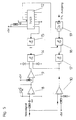
Die Erfindung wird nachstehend anhand der Zeichnung näher erläutert. Es zeigen:
- Fig. 1 ein einer Fließpresse zugeordnetes Transportmittel zum Abführen der Preßteile sowie eine über der Transporteinrichtung an der Meßstelle angeordnete Kamera;
- Fig. 2a, 2b die räumliche Zuordnung von Kamera, Lampe und Meßobjekt (Preßteil) a) in Seitenansicht, b) in Drausicht;
- Fig. 3 den Verlauf des Lichtreflexes auf der Oberseite eines Preßteils;
- Fig. 4 ein Blockschaltbild einer Videosignalverarbeitungseinrichtung; und
- Fig. 5 ein konkretes Schaltbild der Videosignalverarbeitungseinrichtung gemäß Fig. 4.
- 1 shows a transport means assigned to an extrusion press for removing the pressed parts and a camera arranged above the transport device at the measuring point;
- 2a, 2b the spatial assignment of camera, lamp and measuring object (pressed part) a) in side view, b) in plan view;
- 3 shows the course of the light reflex on the top of a pressed part;
- Fig. 4 is a block diagram of a video signal processing device; and
- 5 shows a concrete circuit diagram of the video signal processing device according to FIG. 4.
Schmiermittelnebel, erhöhte Temperatur, schlechte Licht- und Beleuchtungsverhältnisse sowie Erschütterungen schließen die Erfassung der Länge des Preßteils direkt an der Umformstelle aus. Wie aus Fig. 1 ersichtlich, werden die Preßteile 1 nach dem intermittierend arbeitenden Umformprozeß von einer nicht gezeigten Abnahmevorrichtung in Schalen 2 eines Transportmittels 22 abgelegt, das die Preßteile 1 zur Folgemaschine weiterbefördert. Die Preßteile 1 werden unmittelbar nach dem Austritt aus der Fließpresse ausgerichtet. Hierzu werden die Preßteile 1 mittels nicht gezeigten Blasdüsen an ein Leitblech 3 befördert, das dem Transportmittel 22 zugeordnet ist. Dies bedeutet, daß jetzt der Abstand der Schulter bzw. des Bodens des Preßteils 1 zum Leitblech 3 praktisch der Mantellänge des Preßteils entspricht. Deshalb braucht die über der Transporteinrichtung 22 angebrachte Kamera 4 nur die Lage der Schulter bzw. des Bodens des Preßteils 1 erfassen. Dies hat den Vorteil, daß nur ein Hell-Dunkel-Übergang ausgewertet werden muß, um eine Aussage über die Länge des Preßteils 1 zu erhalten. Entsprechend gering ist der elektronische Aufwand. Die Halterung 5 der Kamera 4 ist dabei so angebracht, daß die Preßteile 1 direkt nach der Ausrichtstation erfaßt werden können.Lubricant mist, elevated temperature, poor lighting and lighting conditions and vibrations preclude the detection of the length of the pressed part directly at the forming point. As can be seen from Fig. 1, the pressed parts 1 after the intermittently working forming process from a not shown removal device in shells 2 one Transport means 22 stored, which transports the pressed parts 1 to the following machine. The pressed parts 1 are aligned immediately after they emerge from the extrusion press. For this purpose, the pressed parts 1 are conveyed to a
Zur Einhaltung der Grundstellung gibt es folgende Einstellmöglichkeiten: Die Neigung des Kamerablickwinkels ist zwischen 40 bis 50° einstellbar, und zwar bezogen auf die Abtransportrichtung der Preßteile. Die verstellbare Höhe über dem Transportmittel 22 ergibt sich aus der Abtastentfernung von 200 bis 300 mm. Die Längeneinstellung der Kamera wird querverschiebbar zur Preßteiltransportrichtung im entsprechenden Formatbereich vorgenommen.The following setting options are available for maintaining the basic position: The inclination of the camera viewing angle can be adjusted between 40 and 50 °, based on the direction in which the pressed parts are removed. The adjustable height above the transport means 22 results from the scanning distance of 200 to 300 mm. The length of the camera is adjusted so that it can be moved across the direction of the pressed part in the appropriate format range.
Wie in Fig. 2 dargestellt, benötigt die Kamera 4, um exakt arbeiten zu können, einen guten Kontrast zwischen Preßteil und Hintergrund (Transportstege, die die Schalen des Transportmittels ausbilden). Der Erfassungsbereich muß beleuchtet werden, um optimale Bedingungen zu erreichen. Hierzu wird eine Leuchte 6 direkt über dem Transportmittel 22 in ca. 100 mm Abstand zu den vorbeilaufenden Preßteilen 1 angebracht. Weiterhin muß die Leuchte 6 so montiert sein, daß der erzeugte Lichtreflex auf dem Preßteil 1 zuerst am Kopf und entsprechend versetzt am Ende erscheint. Die Leuchte 6 wird deshalb wie aus Fig. 2 ersichtlich um ca. 20 bis 30° verschwenkt angebracht. Demgegenüber müssen die Transportstege 7, die die Ränder der Schale 2 bilden, entsprechend ausgebildet sein, um einen hohen Kontrast zu erreichen. Holzstege werden aus diesem Grund dunkel gebeizt. Blechstege werden aus bruniertem Material gefertigt.As shown in FIG. 2, the
Die Fig. 3 zeigt den Verlauf des durch die Leuchte sich ergebenden Verlaufs des Lichtreflex auf der Preßteiloberseite.3 shows the course of the course of the light reflection resulting from the lamp on the upper part of the pressed part.
Da das Preßteil 1 nicht sofort in das optimale Blickfeld und in den genauen Schärfentiefenbereich der Kamera 4 gelangt und eine einfache Komparatorschaltung somit zu verschiedenen Zeitpunkten, während das Preßteil das Blickfeld der Kamera 4 durchläuft, verschiedene Längen liefern würde, wird somit das Videosignal nach seiner optimalen Schärfe beurteilt, was somit einem konstanten Abstand zwischen Preßteil 1 und Kamera 4 entspricht.Since the press part 1 does not immediately get into the optimal field of view and the exact depth of field of the
Die Beurteilung, wann das Videosignal die größte Schärfe aufweist, übernimmt, wie aus Fig. 4 ersichtlich, ein Differenzierer 8 in Verbindung mit einem ersten Komparator 9. Dieser Komparator 9 vergleicht die Amplitude des differenzierten Videosignals mit einem vorgegebenen Schwellwert. Überschreiten die Spannungsspitzen des differenzierten Signals des Komparators 9 den vorgegebenen Schwellwert, so schaltet der Komparator 9. Auch die Preßteilkante liefert einen starken Lichtreflex, der den Komparator zum Schalten bringt. Das Ausgangssignal ist aufgrund der Zeitkonstante des Differenzierers 8 in seiner Länge gedeht. Somit reicht der Kantenimpuls geringfügig in seiner Länge über die eigentliche Länge des Preßteils hinaus.4, a
Ein aus dieser Kombination "Differenzierer 8 - erster Komparator 9" - gewonnenes Signal wird mit einem Signal eines zweiten Komparators 10, welches aus dem Videosignal entsteht, logisch verknüpft. Dieser zweite Komparator 10 liefert aufgrund seiner niederen Ansprechschwelle immer ein Ausgangssignal, welches von der momentanen Videosignalbreite abhängt. Der niedere Schwellwert ist notwendig, um die Kanten des Preßteils 1 sicher zu erfassen. Durch die logische Verknüpfung des Längensignals des zweiten Komparators 10 mit dem Schärfesignal des ersten Komparators 9 mittels einer logischen Verknüpfungseinrichtung 11 wird ein Signal erzeugt, das ein nachgeschaltetes Monoflop 12 zum Zeitpunkt der optimalen Schärfe des Videosignal triggert. Die Dauer des Monoflopimpulses reicht zeitlich in das nächste Meßintervall hinein und läßt nun über eine Torschaltung 13 das Ausgangssignal des zweiten Komparators 10 am Ausgang der Schaltung zu. Der am Ausgang der Schaltung nun anliegende Rechteckimpuls entspricht in seiner zeitlichen Länge der Länge des Meßobjekts bzw. Preßteils 1. Liegt andererseits kein Monoflopimpuls am Strobeeingang eines nachfolgend näher beschriebenen NAND-Glieds der Torschaltung 13 an, an dem auch das Signal des zweiten Komparators 10 anliegt, so gelangt kein dosenlängenabhängiges Signal an den Ausgang der Schaltung.A signal obtained from this combination "differentiator 8 -
Wie aus Fig. 5 ersichtlich, die die konkrete Realisierung des in Fig. 4 gezeigten Blockschaltbilds wiedergibt, bestehen die beiden Komparatoren 9, 10 sowie der Differenzierer 8 aus Operationsverstärkern mit entsprechender Beschaltung. Die logische Verknüpfungseinrichtung 11, an deren beiden Eingängen die Ausgangssignale des ersten und zweiten Komparators 9, 10 anliegen, besteht aus einem ersten NAND-Glied 14, dem ein zweites NAND-Glied 15 nachgeschaltet ist. Das Ausgangssignal des zweiten NAND-Glieds 15 steuert das Monoflop 12 an. Die Torschaltung 13 besteht aus einem dritten und vierten NAND-Glied 17, 18 sowie einem NOR-Glied 19. Am Eingang des dritten NAND-Glieds 17 liegt das Ausgangssignal des zweiten Komparators 10 an. Der Ausgang des Monoflops 12 und der Ausgang des dritten NAND-Glieds 17 stehen mit dem vierten NAND-Glied 18 in Verbindung. Der Ausgang des vierten NAND-Glieds 18 ist schließlich mit dem Eingang des NOR-Glieds 19 verbunden, das als Ausgangssignal ein der Preßteillänge proportional es Signal liefert.5, which shows the concrete implementation of the block diagram shown in FIG. 4, the two
Das Ausgangssignal der vorstehend beschriebenen Videosignalverarbeitungseinrichtung stellt ein der Preßteillänge proportionales Signal dar, das mit einem Sollwert verglichen und zur Ansteuerung der elektromechanischen Keilverstellung benutzt wird. Die elektromechanische Keilverstellung beeinflußt die Länge nur indirekt durch Veränderung der Bodendicke bzw. Schulterdicke des Preßteils 1. Zwischen Längenänderung und Dickenänderung besteht ein mathematischer Zusammenhang, in den der Preßteildurchmesser und die Wandstärke einfließen. Die benötigten Werte werden durch Codierschalter zugeführt und die Regelelektronik wandelt die Sol lwertlängenabweichung direkt in eine Drehwinkeländerung an der Verstellspindel um. Ein Elektromotor zur Spindelbetätigung wird eingeschaltet, und dann, wenn die Spindel mit angekoppeltem Winkelimpulsgeber die Verstellung ausgeführt hat, wieder ausgeschaltet.The output signal of the video signal processing device described above represents a signal which is proportional to the length of the pressed part and which is compared with a desired value and used to control the electromechanical wedge adjustment. The electromechanical wedge adjustment affects the length only indirectly by changing the base or shoulder thickness of the pressed part 1. There is a mathematical relationship between the change in length and the change in thickness, into which the diameter of the pressed part and the wall thickness are incorporated. The required values are supplied by coding switches and the control electronics convert the target value length deviation directly into a change in the angle of rotation on the adjusting spindle. An electric motor for spindle actuation is switched on and then switched off again when the spindle has carried out the adjustment with the angular pulse generator coupled.
Bei Formatwechsel muß die Längeregeleinrichtung an die sich ändernden Parameter angepaßt werden. Der Außendurchmesser und die Wanddicke werden jeweils an einem Codierschaltelement eingegeben. Das Längenmaß wird durch Verschieben der Kamera erreicht. Hierzu ist, wie aus Fig. 1 ersichtlich, eine Skala 23 an der Verschiebeeinrichtung 24 so angebracht, daß das Längenmaß direkt in mm ablesbar ist. Genausogut ist es möglich, diese Verschiebeeinrichtung 24 elektromotorisch anzutreiben, mit der Möglichkeit, auch das Längenmaß über Codierschaltelemente einzugeben. Gegebenenfalls ist noch eine Korrektur der Kameraneigung notwendig, um eine ausreichende Tiefenschärfe zu erhalten.When changing the format, the length control device must be adapted to the changing parameters. The outer diameter and the wall thickness are each entered on a coding switching element. The length dimension is achieved by moving the camera. For this purpose, as can be seen from FIG. 1, a
Nach abgeschlossener Formatumstellung kann die Fließpresse wieder in Betrieb gesetzt werden. Die Regelvorrichtung erkennt Abweichungen vom eingestellten Sollwert und nimmt dann die entsprechende Korrektur an der Keilverstellung vor. Weiterhin werden zu große, zu kleine und zumeist deformierte Preßteile erkannt und registriert, um sie später auszuschleusen. Dies bedeutet, daß während der Produktion kein manueller Eingriff nötig ist.After the format change has been completed, the extrusion press can be put back into operation. The control device detects deviations from the set value and then makes the corresponding correction on the wedge adjustment. Furthermore, too large, too small and mostly deformed pressed parts are recognized and registered in order to discharge them later. This means that no manual intervention is necessary during production.
Claims (11)
dadurch gekennzeichnet,
daß die aus der Fließpresse durch das Transportmittel herausgeführten Preßteile einseitig ausgerichtet werden, wobei unmittelbar nach dem Ausrichten während des Vorbeitransports das freiliegende Ende der Preßteile von einer Lichtquelle beleuchtet und das von der Oberfläche reflektierte Licht von einer Kamera zur Verarbeitung in Meßsignale erfaßt wird.1. A method for the automatic electronic control of the length of extrusions such as tubes, cans or the like by measuring the length of the extrusions led out by a means of transport from the extruder, generating a measurement signal, comparing the measurement signal with a specified signal representing the desired size and, if necessary Generating a control signal for adjusting the adjustment part of the press ram of the extrusion press,
characterized by
that the extruded parts led out of the extruder by the transport means are aligned on one side, with the exposed end of the extruded parts being illuminated by a light source immediately after the alignment while being transported past and the light reflected from the surface being detected by a camera for processing in measurement signals.
- einem Transportmittel, das Preßteile aus der Fließpresse herausführt,
- einer Meßeinrichtung zum Feststellen der Preßteillänge,
- einer Vergleichseinrichtung zum Vergleich des der Preßteillänge entsprechenden Signals mit einem Sollwert und
- einer von dem der Abweichung der Preßteillänge vom Sollwert proportionalem Signal angesteuerten Stelleinrichtung, die eine entsprechende Nachstellung des Verstellkeils des Preßstempels der Fließpresse vornimmt,
dadurch gekennzeichnet, daß die Meßeinrichtung aufweist:
- eine dem Transportmittel (22) zugeordnete Preßteil-Ausrichteinrichtung (3),
- eine Beleuchtungseinrichtung (6), die zuerst am Kopf bzw. am Boden des Preßteils (1) und entsprechend versetzt am Ende einen Lichtreflex erzeugt,
- eine Bildaufnahmeeinrichtung (4), die das von der Oberfläche des Preßteils (1) reflektierte Licht erfaßt und ein entsprechende Videosignal erzeugt, und
- eine Videosignalverarbeitungseinrichtung (8 - 13), die das der Abweichung der Preßteillänge vom Sollwert proportionale Signal erzeugt, wobei die Länge des TTL-Signals dem gemessenen Ist-Wert entspricht.3. Device for performing the method according to claim 1 or 2, with
- a means of transport that leads pressed parts out of the extrusion press,
a measuring device for determining the length of the pressed part,
- A comparison device for comparing the signal corresponding to the length of the pressed part with a desired value and
an actuating device which is actuated by the signal proportional to the deviation of the press part length from the target value and which carries out a corresponding adjustment of the adjusting wedge of the press ram of the extrusion press
characterized in that the measuring device comprises:
a pressing part alignment device (3) assigned to the transport means (22),
a lighting device (6) which first generates a light reflex at the head or at the bottom of the pressing part (1) and correspondingly offset at the end,
- An image recording device (4) which detects the light reflected from the surface of the pressing part (1) and generates a corresponding video signal, and
- A video signal processing device (8 - 13) which generates the signal proportional to the deviation of the length of the pressed part from the target value, the length of the TTL signal corresponding to the measured actual value.
daß der Ausgang des zweiten NAND-Glieds (15) mit dem Eingang des Monoflops (12) verbunden ist, daß die Torschaltung (13) ein drittes und viertes NAND-Glied (17 und 18) sowie ein NOR-Glied (19) aufweist, wobei der Ausgang des zweiten Komparators (10) mit dem Eingang des dritten NAND-Glieds (17) verbunden ist und der Ausgang des Monoflops (12) sowie der Ausgang des dritten NAND-Glieds (17) mit den Eingängen des vierten NAND-Glieds verbunden sind und der Ausgang des vierten NAND-Glieds (18) mit dem Eingang des NOR-Glieds (19) in Verbindung steht, das als Ausgangssignal ein der Abweichung der Preßteillänge vom Sollwert proportionales Signal liefert, wobei die Abweichung vom Sollwert mit Hilfe eines Single-board Prozessors ermittelt und dann in eine Stellgröße umgewandelt wird.11. Device according to one of claims 7 to 10, characterized in that the logic circuit consists of a logic logic device (11), a monoflop (12) and a gate circuit (13), that the logic device (11) is a first NAND element (14), the two inputs of which are connected to the outputs of the first and second comparators (9 and 10), as well as a second NAND element (15), the input of which connects to the output of the first NAND element (14) in Connection is established
that the output of the second NAND gate (15) is connected to the input of the monoflop (12), that the gate circuit (13) has a third and fourth NAND gate (17 and 18) and a NOR gate (19), the output of the second comparator (10) being connected to the input of the third NAND gate (17) and the output of the monoflop (12) and the output of the third NAND gate (17) are connected to the inputs of the fourth NAND gate and the output of the fourth NAND gate (18) to the input of the NOR gate (19) is connected, which provides a signal proportional to the deviation of the pressed part length from the setpoint as output signal, the deviation from the setpoint being determined with the aid of a single-board processor and then converted into a manipulated variable.
Applications Claiming Priority (2)
| Application Number | Priority Date | Filing Date | Title |
|---|---|---|---|
| DE3909542A DE3909542A1 (en) | 1989-03-22 | 1989-03-22 | METHOD AND DEVICE FOR REGULATING THE LENGTH OF PRESSING PARTS, LIKE TUBES, CANES OR THE LIKE, MADE IN FLOW PRESSES |
| DE3909542 | 1989-03-22 |
Publications (3)
| Publication Number | Publication Date |
|---|---|
| EP0388949A2 true EP0388949A2 (en) | 1990-09-26 |
| EP0388949A3 EP0388949A3 (en) | 1991-07-31 |
| EP0388949B1 EP0388949B1 (en) | 1993-11-18 |
Family
ID=6377025
Family Applications (1)
| Application Number | Title | Priority Date | Filing Date |
|---|---|---|---|
| EP19900105430 Expired - Lifetime EP0388949B1 (en) | 1989-03-22 | 1990-03-22 | Method and device for the automatic electronic control of the length of moulded articles produced in extruders |
Country Status (2)
| Country | Link |
|---|---|
| EP (1) | EP0388949B1 (en) |
| DE (2) | DE3909542A1 (en) |
Cited By (2)
| Publication number | Priority date | Publication date | Assignee | Title |
|---|---|---|---|---|
| EP3404357A1 (en) | 2017-05-18 | 2018-11-21 | Tech Pro Packag S.L. | Method and apparatus for the control of containers |
| CN110146023A (en) * | 2019-05-31 | 2019-08-20 | 广东斯丹诺智能装备有限公司 | Aluminum alloy pattern plate length laser detection |
Families Citing this family (4)
| Publication number | Priority date | Publication date | Assignee | Title |
|---|---|---|---|---|
| DE29705781U1 (en) * | 1997-04-02 | 1997-05-15 | Festo Kg | Device for recognizing incorrectly oriented and / or parts deviating from a predetermined pattern |
| US6134027A (en) * | 1997-10-23 | 2000-10-17 | Mustek Systems, Inc. | Method and device for determining scanning dimension |
| DE102012101952B4 (en) | 2012-03-08 | 2016-03-03 | Schuler Pressen Gmbh | Press and method for producing a can body with automatic adjustment of the bottom thickness |
| CN112536235A (en) * | 2020-11-11 | 2021-03-23 | 安徽锦希自动化科技有限公司 | Part length detection device applied to automatic cutting machine |
Citations (3)
| Publication number | Priority date | Publication date | Assignee | Title |
|---|---|---|---|---|
| US3109927A (en) * | 1961-04-20 | 1963-11-05 | Florida Tile Ind Inc | Tile size responsive apparatus and control |
| EP0034088A1 (en) * | 1980-02-12 | 1981-08-19 | Supermarket Systems | Apparatus for the identification of objects such as bottles |
| DE3325965A1 (en) * | 1983-07-19 | 1985-02-07 | BFI-Beratungsgesellschaft für Industrie-Elektronik mbH + Co KG, 5600 Wuppertal | Method and device for producing ceramic tiles |
Family Cites Families (3)
| Publication number | Priority date | Publication date | Assignee | Title |
|---|---|---|---|---|
| FR1555808A (en) * | 1967-12-11 | 1969-01-31 | ||
| JPS5737806B2 (en) * | 1972-12-27 | 1982-08-12 | ||
| US4647208A (en) * | 1985-07-22 | 1987-03-03 | Perceptron, Inc. | Method for spatial measurement of holes |
-
1989
- 1989-03-22 DE DE3909542A patent/DE3909542A1/en not_active Withdrawn
-
1990
- 1990-03-22 EP EP19900105430 patent/EP0388949B1/en not_active Expired - Lifetime
- 1990-03-22 DE DE90105430T patent/DE59003498D1/en not_active Expired - Fee Related
Patent Citations (3)
| Publication number | Priority date | Publication date | Assignee | Title |
|---|---|---|---|---|
| US3109927A (en) * | 1961-04-20 | 1963-11-05 | Florida Tile Ind Inc | Tile size responsive apparatus and control |
| EP0034088A1 (en) * | 1980-02-12 | 1981-08-19 | Supermarket Systems | Apparatus for the identification of objects such as bottles |
| DE3325965A1 (en) * | 1983-07-19 | 1985-02-07 | BFI-Beratungsgesellschaft für Industrie-Elektronik mbH + Co KG, 5600 Wuppertal | Method and device for producing ceramic tiles |
Cited By (2)
| Publication number | Priority date | Publication date | Assignee | Title |
|---|---|---|---|---|
| EP3404357A1 (en) | 2017-05-18 | 2018-11-21 | Tech Pro Packag S.L. | Method and apparatus for the control of containers |
| CN110146023A (en) * | 2019-05-31 | 2019-08-20 | 广东斯丹诺智能装备有限公司 | Aluminum alloy pattern plate length laser detection |
Also Published As
| Publication number | Publication date |
|---|---|
| DE59003498D1 (en) | 1993-12-23 |
| DE3909542A1 (en) | 1990-09-27 |
| EP0388949B1 (en) | 1993-11-18 |
| EP0388949A3 (en) | 1991-07-31 |
Similar Documents
| Publication | Publication Date | Title |
|---|---|---|
| DE3543846C2 (en) | ||
| DE3210046A1 (en) | METHOD AND DEVICE FOR AUTOMATICALLY CONTROLLING A CUTTING MACHINE | |
| EP0166351A2 (en) | Device at a machine for deformation work of sheet metals | |
| DE19751862A1 (en) | Method and equipment for identifying and sorting objects transported on belt conveyor | |
| EP0520396A1 (en) | Automatic measuring of a working tool | |
| DE2949642A1 (en) | METHOD AND DEVICE FOR CONTROLLING THE OPERATION OF A COPY CUTTING DEVICE | |
| EP0087644B1 (en) | Turning multiple-winding machine | |
| EP0388949B1 (en) | Method and device for the automatic electronic control of the length of moulded articles produced in extruders | |
| DE3430463A1 (en) | METHOD AND DEVICE FOR AUTOMATIC PUNCHING | |
| EP2228232A1 (en) | Device for monitoring and regulating an adhesive layer to a be applied when producing printed products | |
| CH658211A5 (en) | ARRANGEMENT FOR BASIC ADJUSTMENT, MONITORING AND RE-ADJUSTING THE INCLINATION OF THE NARROW-SIDE PLATES OF AN ADJUSTABLE SLAB-CHOCOLATE. | |
| DE2916115C2 (en) | Electric copy control device | |
| DE2443383B2 (en) | Control device for the grinding carriage infeed speed on cylindrical grinding machines | |
| EP0400476B2 (en) | Laser machining method | |
| DE2850794C2 (en) | ||
| DE3320160C2 (en) | Device for coating ceramic plates, preferably for applying a layer of glaze | |
| DE10355051B4 (en) | Method and apparatus for laser beam welding with reduced marking | |
| EP2050567A2 (en) | Method to align a carrier material that is to be printed | |
| EP1625911A1 (en) | Wire bonder with a camera, a device for image treatment, memoires et comparing means and process using this wire bonder | |
| DE3622845A1 (en) | Method and apparatus for automatically blanking out printed parts from workpiece plates | |
| DE4029827A1 (en) | ELECTRIC WIRE CUT DISCHARGE PROCESSING DEVICE | |
| DE3200075C2 (en) | Method and device for the automatic sorting of screws with heads | |
| CH668135A5 (en) | METHOD AND DEVICE FOR SORTING COINS. | |
| DE3510644A1 (en) | METHOD FOR MEASURING PARTICULAR ROTATION-SYMMETRICAL WORKPIECES | |
| DE4203952A1 (en) | DEVICE AND METHOD FOR POSITIONING THE SENSORS IN A PATTERN CONTROL DEVICE |
Legal Events
| Date | Code | Title | Description |
|---|---|---|---|
| PUAI | Public reference made under article 153(3) epc to a published international application that has entered the european phase |
Free format text: ORIGINAL CODE: 0009012 |
|
| AK | Designated contracting states |
Kind code of ref document: A2 Designated state(s): CH DE FR GB IT LI NL |
|
| PUAL | Search report despatched |
Free format text: ORIGINAL CODE: 0009013 |
|
| AK | Designated contracting states |
Kind code of ref document: A3 Designated state(s): CH DE FR GB IT LI NL |
|
| 17P | Request for examination filed |
Effective date: 19920131 |
|
| 17Q | First examination report despatched |
Effective date: 19930108 |
|
| GRAA | (expected) grant |
Free format text: ORIGINAL CODE: 0009210 |
|
| AK | Designated contracting states |
Kind code of ref document: B1 Designated state(s): CH DE FR GB IT LI NL |
|
| RAP4 | Party data changed (patent owner data changed or rights of a patent transferred) |
Owner name: HERLAN & CO. MASCHINENFABRIK GMBH & CO. KG |
|
| REF | Corresponds to: |
Ref document number: 59003498 Country of ref document: DE Date of ref document: 19931223 |
|
| ITF | It: translation for a ep patent filed |
Owner name: ORGANIZZAZIONE D'AGOSTINI |
|
| GBT | Gb: translation of ep patent filed (gb section 77(6)(a)/1977) |
Effective date: 19940217 |
|
| ET | Fr: translation filed | ||
| PLBE | No opposition filed within time limit |
Free format text: ORIGINAL CODE: 0009261 |
|
| STAA | Information on the status of an ep patent application or granted ep patent |
Free format text: STATUS: NO OPPOSITION FILED WITHIN TIME LIMIT |
|
| 26N | No opposition filed | ||
| PGFP | Annual fee paid to national office [announced via postgrant information from national office to epo] |
Ref country code: GB Payment date: 19950821 Year of fee payment: 6 |
|
| PGFP | Annual fee paid to national office [announced via postgrant information from national office to epo] |
Ref country code: CH Payment date: 19950822 Year of fee payment: 6 |
|
| PGFP | Annual fee paid to national office [announced via postgrant information from national office to epo] |
Ref country code: FR Payment date: 19950828 Year of fee payment: 6 |
|
| PGFP | Annual fee paid to national office [announced via postgrant information from national office to epo] |
Ref country code: NL Payment date: 19950829 Year of fee payment: 6 |
|
| PGFP | Annual fee paid to national office [announced via postgrant information from national office to epo] |
Ref country code: DE Payment date: 19950831 Year of fee payment: 6 |
|
| PG25 | Lapsed in a contracting state [announced via postgrant information from national office to epo] |
Ref country code: GB Effective date: 19960322 |
|
| PG25 | Lapsed in a contracting state [announced via postgrant information from national office to epo] |
Ref country code: LI Effective date: 19960331 Ref country code: CH Effective date: 19960331 |
|
| PG25 | Lapsed in a contracting state [announced via postgrant information from national office to epo] |
Ref country code: NL Effective date: 19961001 |
|
| GBPC | Gb: european patent ceased through non-payment of renewal fee |
Effective date: 19960322 |
|
| REG | Reference to a national code |
Ref country code: CH Ref legal event code: PL |
|
| PG25 | Lapsed in a contracting state [announced via postgrant information from national office to epo] |
Ref country code: FR Effective date: 19961129 |
|
| NLV4 | Nl: lapsed or anulled due to non-payment of the annual fee |
Effective date: 19961001 |
|
| PG25 | Lapsed in a contracting state [announced via postgrant information from national office to epo] |
Ref country code: DE Effective date: 19961203 |
|
| REG | Reference to a national code |
Ref country code: FR Ref legal event code: ST |
|
| PG25 | Lapsed in a contracting state [announced via postgrant information from national office to epo] |
Ref country code: IT Free format text: LAPSE BECAUSE OF NON-PAYMENT OF DUE FEES;WARNING: LAPSES OF ITALIAN PATENTS WITH EFFECTIVE DATE BEFORE 2007 MAY HAVE OCCURRED AT ANY TIME BEFORE 2007. THE CORRECT EFFECTIVE DATE MAY BE DIFFERENT FROM THE ONE RECORDED. Effective date: 20050322 |