EP0388352A1 - One way light barrier arrangement - Google Patents
One way light barrier arrangement Download PDFInfo
- Publication number
- EP0388352A1 EP0388352A1 EP90810116A EP90810116A EP0388352A1 EP 0388352 A1 EP0388352 A1 EP 0388352A1 EP 90810116 A EP90810116 A EP 90810116A EP 90810116 A EP90810116 A EP 90810116A EP 0388352 A1 EP0388352 A1 EP 0388352A1
- Authority
- EP
- European Patent Office
- Prior art keywords
- transmitters
- transmitter
- light barrier
- receivers
- receiver
- Prior art date
- Legal status (The legal status is an assumption and is not a legal conclusion. Google has not performed a legal analysis and makes no representation as to the accuracy of the status listed.)
- Withdrawn
Links
Images


Classifications
-
- G—PHYSICS
- G08—SIGNALLING
- G08B—SIGNALLING OR CALLING SYSTEMS; ORDER TELEGRAPHS; ALARM SYSTEMS
- G08B13/00—Burglar, theft or intruder alarms
- G08B13/18—Actuation by interference with heat, light, or radiation of shorter wavelength; Actuation by intruding sources of heat, light, or radiation of shorter wavelength
- G08B13/181—Actuation by interference with heat, light, or radiation of shorter wavelength; Actuation by intruding sources of heat, light, or radiation of shorter wavelength using active radiation detection systems
- G08B13/183—Actuation by interference with heat, light, or radiation of shorter wavelength; Actuation by intruding sources of heat, light, or radiation of shorter wavelength using active radiation detection systems by interruption of a radiation beam or barrier
-
- G—PHYSICS
- G08—SIGNALLING
- G08B—SIGNALLING OR CALLING SYSTEMS; ORDER TELEGRAPHS; ALARM SYSTEMS
- G08B29/00—Checking or monitoring of signalling or alarm systems; Prevention or correction of operating errors, e.g. preventing unauthorised operation
- G08B29/18—Prevention or correction of operating errors
Definitions
- the invention relates to a one-way light barrier arrangement with a series of monitoring sections or data and / or signal transmission sections, a transmitter and a receiver being provided for each section.
- the one-way light barrier arrangement contains two types of transmitters and receivers, the first type being a linear polarization filter with a first polarization level and the second type has a linear polarization filter with a second polarization level, which is arranged at an angle to the first polarization level, and that the transmitter and receiver are of the same type for the respective route.
- first type being a linear polarization filter with a first polarization level
- second type has a linear polarization filter with a second polarization level, which is arranged at an angle to the first polarization level, and that the transmitter and receiver are of the same type for the respective route.
- a one-way light barrier arrangement is thus possible, in which all transmitters are arranged on one side and all receivers on the other side if the lines are alternately equipped with one or the other type of transmitters and receivers (FIG. 3). With this arrangement, stray light from the neighboring route does not interfere. Only stray light from a third distance could have a disturbing effect, provided that it is still of sufficient intensity.
- An embodiment is even more advantageous, which is characterized in that transmitters or receivers are alternately arranged in groups of two on one side or the other side, and that in successive routes the transmitters and receivers are alternately of the first or the second type ( Fig. 4).
- only the fifth route is in turn configured the same as the first, so that only the receiver of the fifth route could be influenced by stray light from the first route.
- the fifth route is far away, either no stray light falls on the receiver or the striking stray light is so low in intensity that it has no effect.
- the angle between the first and the second plane of polarization is advantageously 90 degrees. At this angle, influencing of a receiver of the second type by a transmitter of the first type is practically impossible, because then practically all striking polarized light is filtered out.
- An advantageous arrangement provides that the even-numbered segments are arranged in a first plane and the odd-numbered segments in a second plane, which extends at a distance parallel to the first plane (FIG. 6). This arrangement is particularly advantageous if the transmitter and receiver have a common fastening axis, which allows such an arrangement.
- the transmitters S1, S2, S3 are arranged on one side, the receivers E1, E2, E3 on the other side. As shown in dash-dotted lines, there is a risk that stray light from a transmitter, e.g. S1, the receiver, e.g. E2, which can affect the neighboring route.
- the transmission directions in the known arrangement from FIG. 2 are alternately different.
- the transmitter S1, the receiver E2 and the transmitter S3 are arranged on the one side, while the receiver E1, the transmitter S2 and the receiver E3 are located on the other side.
- stray light from one route cannot affect the receiver of the neighboring route.
- a number of distances D1, D2, D3 ... are again provided.
- the first type contains a linear polarization filter with a first polarization plane that is indicated with four vertical lines.
- the second type contains a linear polarization filter with a second polarization plane, which is indicated by four horizontal lines.
- the second polarization plane is arranged at an angle of 90 degrees to the first polarization plane.
- the transmitter and the receiver have linear polarization filters with the same polarization level; The transmitter and receiver are thus of the same type.
- the transmitters S1, S2, S3 ... are arranged on one side and the receivers E1, E2, E3 ...
- the lines D1, D2, D3 ... are equipped in sequence with transmitters and receivers of one or the other type. It can be seen that, in these circumstances, the transmitter S1, for example, cannot influence the adjacent receiver E2. Scattered light from the transmitter S1 could only influence the receiver E3, which has the same polarization as the transmitter S1.
- the embodiment of FIG. 3 does not differ from the known prior art according to FIG. 2, but has the advantage that all transmitters can be on one side or all transmitters on the other side, as is appropriate for certain applications.
- the transmitters S1, S2 are alternately of the first or second type. Furthermore, the transmitters S1, S2 are alternately in groups of two arranged on one or the other side. The groups of two are indicated by brackets.
- the same also applies to the receivers E1, E2, ... With this arrangement, for example, scattered light from the transmitter S1 cannot influence the adjacent three receivers E2, E3 and E4. Stray light from the transmitter S1 could only fall onto the receiver E5. However, this is hardly the case because the distance from the distance D1 is relatively large. Scattered light that may fall on the receiver E5 is usually of such a low intensity that it has no interference.
- the embodiment according to FIG. 5 gives the same advantage, where in successive distances D1, D2 ... the transmitters or Receivers are arranged alternately on one side and the other. Again, groups of two transmitters and receivers are provided, the transmitters and receivers being of the same type in such a group of two. The groups of two transmitters and receivers are alternately of the first and the second type, as indicated by the vertical and horizontal lines.
- the odd-numbered lines are arranged in a first plane P1 and the even-numbered lines in a second plane P2, which extends parallel to the first plane at a distance d.
- This arrangement is practical if the housing of the transmitter and receiver have a common fastening axis A1 or A2.
- transmitters S1, S2, ... are alternately of the first or second type. Furthermore, the transmitters S1, S2 are alternately arranged in groups of two on one side or the other. (In the schematic representation above or below in the picture). The same applies to the receivers E1, E2, ... In contrast to FIG. 4, however, the odd-numbered transmitters and receivers are arranged in the level P1 and the even-numbered ones in the level P2.
- the transmitters S1, S2, ... are alternately arranged on one side or the other. (In the schematic representation above or below in the picture). The same also applies to the receivers E1, E2, ... Furthermore, groups of two transmitters and receivers are alternately of the first or second type. In contrast to FIG. 5, however, the odd-numbered transmitters and receivers are in level P1 and the even-numbered ones in the level P2 arranged.
- the transmitter and / or receiver which are on one or the other ren side are each arranged in a common housing.
- the one-way light barrier arrangement in the form of a fork light barrier arrangement. With such a design, the transmitter and receiver can be arranged in a common housing.
- Fig. 9 shows the structure of a one-way light barrier. This consists of the transmitter S and the receiver E.
- a stabilized power supply unit 12 which is designed either for the connection of all-current or only alternating current or only direct current.
- the power supply 12 feeds a transmitter circuit 13, which allows a radiation source 14 to work either with continuous light or pulsed light. Depending on the application, the light emanating from the radiation source 14 is bundled or made slightly divergent or convergent.
- the front lens 15 is used for this purpose.
- a linear polarization filter 17 is located between the radiation source 14 and the front lens 15. The linearly polarized light reaches the receiver E via the transmission path d.
- the receiver E has a housing 21 which is advantageously of the same design as the housing 11 of the transmitter S. Behind the front lens 23 is a linear polarization filter 25, which has the same polarization plane as the polarization filter 17.
- the photoelectric converter 27, whose output signal is fed to an electronic amplifier 29, is used to receive the incident received light beam.
- An electronic evaluation stage 31 is connected to the amplifier 29 and is supplied by the stabilized power supply 33.
- the output 34 which can include a light or dark circuit or an antivalence circuit, experiences a signal change when the photoelectric converter receives a light intensity above a predetermined threshold value.
Landscapes
- Physics & Mathematics (AREA)
- General Physics & Mathematics (AREA)
- Engineering & Computer Science (AREA)
- Computer Security & Cryptography (AREA)
- Optical Communication System (AREA)
Abstract
Description
Die Erfindung betrifft eine Einweg-Lichtschrankenanordnung mit einer Reihe von Ueberwachungsstrecken oder Daten- und/oder Signal-Uebertragungsstrecken, wobei für jede Strecke ein Sender und ein Empfänger vorgesehen sind.The invention relates to a one-way light barrier arrangement with a series of monitoring sections or data and / or signal transmission sections, a transmitter and a receiver being provided for each section.
Wenn bei einer Einweg-Lichtschrankenanordnung zwei relativ nahe beieinanderliegende Ueberwachungs- oder Uebertragungsstrecken vorgesehen sind, besteht die Gefahr, dass Licht einer ersten Strecke auf den Empfänger einer zweiten Strecke fällt und eine Fehlschaltung auslöst (Fig. 1). Dieses Problem kann aber dadurch verhindert werden, dass die Uebertragungsrichtung der zweiten Strecke entgegengesetzt zur Uebertragungsrichtung der ersten Strecke angeordnet wird. Da sich in diesem Fall der Empfänger der zweiten Strecke neben dem Sender der ersten Strecke und der Empfänger der ersten Strecke neben dem Sender der zweiten Strecke befindet, ist eine Beeinflussung des jeweiligen Empfängers durch Streulicht des falschen Senders unmöglich. Probleme ergeben sich aber, wenn mehr als zwei Strecken vorhanden sind. Es ist dann möglich, dass beispielsweise Licht vom ersten Sender den dritten Empfänger beeinflussen kann (Fig. 2). Nachteilig ist also die relativ begrenzte Störsicherheit und der Zwang, immer abwechslungsweise Sender und Empfänger auf verschiedenen Seiten anordnen zu müssen.If, in a one-way light barrier arrangement, two relatively closely spaced monitoring or transmission lines are provided, there is a risk that light from a first line will fall onto the receiver of a second line and trigger a malfunction (FIG. 1). However, this problem can be prevented by arranging the direction of transmission of the second route in the opposite direction to the direction of transmission of the first route. In this case, since the receiver of the second route is next to the transmitter of the first route and the receiver of the first route is next to the transmitter of the second route, it is impossible for the respective receiver to be influenced by stray light from the wrong transmitter. Problems arise, however, if there are more than two routes. It is then possible that, for example, light from the first transmitter can influence the third receiver (FIG. 2). Disadvantages are the relatively limited immunity to interference and the obligation to always have to alternately arrange the transmitter and receiver on different sides.
Es ist daher Aufgabe der vorliegenden Erfindung, eine Einweglichtschrankenanordnung mit einer Vielzahl von Ueberwachungs- oder Uebertragungsstrecken zu schaffen, welche dem Anwender mehr Freiheiten bei der Anordnung der Sender und Empfänger lässt und bei welcher praktisch keine Gefahr besteht, dass die Empfänger durch Streulicht von Sendern anderer Strecken beeinflusst werden.It is therefore an object of the present invention to provide a one-way light barrier arrangement with a multiplicity of monitoring or transmission links which gives the user more freedom in the arrangement of the transmitters and receivers and in which there is practically no risk that the receivers are exposed to stray light from transmitters of others Routes are influenced.
Erfindungsgemäss wird dies dadurch erreicht, dass die Einweg-Lichtschrankenanordnung zwei Arten von Sendern und Empfängern enthält, wobei die erste Art ein lineares Polarisationsfilter mit einer ersten Polarisationsebene und die zweite Art ein lineares Polarisationsfilter mit einer zweiten Polarisationsebene aufweist, die in einem Winkel zur ersten Polarisationsebene angeordnet ist, und dass bei der jeweiligen Strecke Sender und Empfänger von der gleichen Art sind. Dies ermöglicht verschiedene Anordnungen von Sendern und Empfängern, wobei jede Strecke weitgehende Immunität gegen Streulicht von anderen Strecken aufweist.This is achieved according to the invention in that the one-way light barrier arrangement contains two types of transmitters and receivers, the first type being a linear polarization filter with a first polarization level and the second type has a linear polarization filter with a second polarization level, which is arranged at an angle to the first polarization level, and that the transmitter and receiver are of the same type for the respective route. This enables different arrangements of transmitters and receivers, each route having extensive immunity to stray light from other routes.
So ist eine Einweg-Lichtschrankenanordnung möglich, bei der alle Sender auf der einen Seite und alle Empfänger auf der anderen Seite angeordnet sind, wenn die Strecken abwechslungsweise mit der einen bzw. der anderen Art von Sendern und Empfängern ausgerüstet sind (Fig. 3). Bei dieser Anordnung stört Streulicht von der benachbarten Strecke nicht. Erst Streulicht von einer dritten Strecke könnte sich störend auswirken, sofern es noch genügende Intensität aufweist.A one-way light barrier arrangement is thus possible, in which all transmitters are arranged on one side and all receivers on the other side if the lines are alternately equipped with one or the other type of transmitters and receivers (FIG. 3). With this arrangement, stray light from the neighboring route does not interfere. Only stray light from a third distance could have a disturbing effect, provided that it is still of sufficient intensity.
Noch vorteilhafter ist eine Ausführungsform, die dadurch gekennzeichnet ist, dass Sender bzw. Empfänger abwechslungsweise in Zweiergruppen auf der einen Seite bzw. anderen Seite angeordnet sind, und dass in aufeinanderfolgenden Strecken die Sender und Empfänger abwechslungsweise von der ersten bzw. der zweiten Art sind (Fig. 4). Bei dieser Anordnung ist erst die fünfte Strecke wiederum gleich ausgestaltet wie die erste, so dass erst der Empfänger der fünften Strecke durch Streulicht der ersten Strecke beeinflusst werden konnte. Da nun aber die fünfte Strecke weit entfernt ist, fällt auf deren Empfänger entweder kein Streulicht oder das auffallende Streulicht ist von so geringer Intensität, dass es ohne Wirkung bleibt.An embodiment is even more advantageous, which is characterized in that transmitters or receivers are alternately arranged in groups of two on one side or the other side, and that in successive routes the transmitters and receivers are alternately of the first or the second type ( Fig. 4). In this arrangement, only the fifth route is in turn configured the same as the first, so that only the receiver of the fifth route could be influenced by stray light from the first route. However, since the fifth route is far away, either no stray light falls on the receiver or the striking stray light is so low in intensity that it has no effect.
Es ist aber auch möglich, eine Lichtschrankenanordnung der eingangs erwähnten Art, bei welcher in benachbarten Strecken die Uebertragungsrichtung verschieden ist, erfindungsgemäss derart auszugestalten, dass in aufeinanderfolgenden Strecken die Sender bzw. Empfänger abwechslungsweise auf der einen oder anderen Seite angeordnet sind, und dass Zweiergruppen von Sendern bzw. Empfängern abwechslungsweise von der ersten bzw. zweiten Art sind (Fig. 5). Auch bei dieser Anordnung unterscheiden sich die einer beliebigen Strecke vorangehenden oder folgenden drei Strecken durch andere Polarität oder andere Uebertragungsrichtung, so dass sie nicht durch Streulicht der erstgenannten Strecke beeinflusst werden können.However, it is also possible to design a light barrier arrangement of the type mentioned at the outset, in which the transmission direction is different in adjacent routes, in such a way that the transmitters or receivers are arranged alternately on one or the other side in successive routes, and that groups of two of Senders or receivers alternately from the first or are of the second type (Fig. 5). In this arrangement, too, the three routes preceding or following an arbitrary route differ in terms of other polarity or different transmission direction, so that they cannot be influenced by stray light from the first route mentioned.
Der Winkel zwischen der ersten und der zweiten Polarisationsebene beträgt vorteilhaft 90 Grad. Bei diesem Winkel ist eine Beeinflussung eines Empfängers der zweiten Art durch einen Sender der ersten Art praktisch ausgeschlossen, weil dann praktisch alles auffallende polarisierte Licht ausgefiltert wird.The angle between the first and the second plane of polarization is advantageously 90 degrees. At this angle, influencing of a receiver of the second type by a transmitter of the first type is practically impossible, because then practically all striking polarized light is filtered out.
Eine vorteilhafte Anordnung sieht vor, dass die geradzahligen Strecken in einer ersten Ebene und die ungeradzahligen Strecken in einer zweiten Ebene angeordnet sind, die sich in einem Abstand parallel zur ersten Ebene erstreckt (Fig. 6). Diese Anordnung ist besonders vorteilhaft, wenn die Sender und Empfänger eine gemeinsame Befestigungsachse aufweisen, welche eine solche Anordnung erlaubt.An advantageous arrangement provides that the even-numbered segments are arranged in a first plane and the odd-numbered segments in a second plane, which extends at a distance parallel to the first plane (FIG. 6). This arrangement is particularly advantageous if the transmitter and receiver have a common fastening axis, which allows such an arrangement.
Die Erfindung wird nun unter Bezug auf die Zeichnung beschrieben. Es zeigt:
- Fig. 1 Eine erste bekannte Lichtschrankenanordnung,
- Fig. 2 eine zweite bekannte Lichtschrankenanordnung,
- Fig. 3 ein erstes Ausführungsbeispiel der erfindungsgemässen Einweg-Lichtschrankenanordnung,
- Fig. 4 ein zweites Ausführungsbeispiel der erfindungsgemässen Einweg-Lichtschrankenanordnung,
- Fig. 5 ein drittes Ausführungsbeispiel der erfindungsgemässen Einweg-Lichtschrankenanordnung,
- Fig. 6 eine Einweg-Lichtschrankenanordnung, bei welcher die Strecken sich in zwei verschiedenen parallelen Ebenen befinden, die in einem Abstand voneinander angeordnet sind,
- Fig. 7 eine erste Anordnung der Sender und Empfänger und der Polarisationsebenen beim Beispiel von Fig. 6,
- Fig. 8 eine zweite Anordnung der Sender und Empfänger und der Polarisationsebenen beim Beispiel von Fig. 6, und
- Fig. 9 den Aufbau einer Einweg-Lichtschranke
- 1 shows a first known light barrier arrangement,
- 2 shows a second known light barrier arrangement,
- 3 shows a first exemplary embodiment of the one-way light barrier arrangement according to the invention,
- 4 shows a second exemplary embodiment of the one-way light barrier arrangement according to the invention,
- 5 shows a third exemplary embodiment of the one-way light barrier arrangement according to the invention,
- 6 shows a one-way light barrier arrangement in which the distances are in two different parallel planes which are arranged at a distance from one another,
- 7 shows a first arrangement of the transmitter and receiver and the polarization planes in the example of FIG. 6,
- Fig. 8 shows a second arrangement of the transmitter and receiver and the polarization planes in the example of Fig. 6, and
- Fig. 9 shows the structure of a one-way light barrier
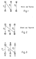
Fig. 1 zeigt eine bekannte Lichtschrankenanordnung mit drei oder mehr Ueberwachungsstrecken oder Daten- und/oder Signal-Uebertragungsstrecken D1, D2, D3..., nachfolgend kurz "Strekken" genannt. Die Sender S1, S2, S3 sind auf einer Seite, die Empfänger E1, E2, E3 auf der anderen Seite angeordnet. Wie strichpunktiert eingezeichnet ist, besteht dabei die Gefahr, dass Streulicht eines Senders, z.B. S1, den Empfänger, z.B. E2, der benachbarten Strecke beeinflussen kann.1 shows a known light barrier arrangement with three or more monitoring links or data and / or signal transmission links D1, D2, D3 ..., hereinafter referred to as "stretches" for short. The transmitters S1, S2, S3 are arranged on one side, the receivers E1, E2, E3 on the other side. As shown in dash-dotted lines, there is a risk that stray light from a transmitter, e.g. S1, the receiver, e.g. E2, which can affect the neighboring route.
Im Gegensatz zur bekannten Anordnung von Fig. 1 sind bei der bekannten Anordnung von Fig. 2 die Uebertragungsrichtungen abwechslungsweise verschieden. Mit anderen Worten, auf der einen Seite ist der Sender S1, der Empfänger E2 und der Sender S3 angeordnet, währenddem auf der anderen Seite sich der Empfänger E1, der Sender S2 und der Empfänger E3 befinden. Bei dieser Anordnung kann Streulicht von einer Strecke den Empfänger der benachbarten Strecke nicht beeinflussen. Möglich ist aber, dass beispielsweise Streulicht des Senders S1 auf den Empfänger E3 fällt.In contrast to the known arrangement from FIG. 1, the transmission directions in the known arrangement from FIG. 2 are alternately different. In other words, the transmitter S1, the receiver E2 and the transmitter S3 are arranged on the one side, while the receiver E1, the transmitter S2 and the receiver E3 are located on the other side. With this arrangement, stray light from one route cannot affect the receiver of the neighboring route. However, it is possible that, for example, stray light from the transmitter S1 falls on the receiver E3.
Beim ersten Ausführungsbeispiel der Einweg-Lichtschrankenanordnung gemäss Fig. 3 sind wiederum eine Anzahl von Strecken D1, D2, D3... vorgesehen. Es sind zwei Arten von Sendern und Empfängern vorgesehen. Die erste Art enthält ein lineares Polarisationsfilter mit einer ersten Polarisationsebene, die mit vier senkrechten Strichen angedeutet ist. Die zweite Art enthält ein lineares Polarisationsfilter mit einer zweiten Polarisationsebene, die mit vier waagrechten Strichen angedeutet ist. Die zweite Polarisationsebene ist in einem Winkel von 90 Grad zur ersten Polarisationsebene angeordnet. Bei der jeweiligen Strecke weisen der Sender und der Empfänger lineare Polarisationsfilter mit der gleichen Polarisationsebene auf; Sender und Empfänger sind somit von der gleichen Art. Die Sender S1, S2, S3... sind auf der einen Seite und die Empfänger E1, E2, E3... auf der anderen Seite angeordnet. Der Reihe nach sind die Strecken D1, D2, D3... mit Sendern und Empfänger der einen bzw. der anderen Art ausgerüstet. Es ist ersichtlich, dass unter diesen Umständen beispielsweise der Sender S1 den benachbarten Empfänger E2 nicht beeinflussen kann. Streulicht vom Sender S1 könnte erst den Empfänger E3, welcher die gleiche Polarisation wie der Sender S1 aufweist, beeinflussen. Insofern unterscheidet sich die Ausführungsform von Fig. 3 nicht vom bekannten Stand der Technik gemäss Fig. 2, hat aber den Vorteil, dass alle Sender auf der einen bzw. alle Sender auf der anderen Seite sein können, wie dies für gewisse Anwendungen zweckmässig ist.In the first exemplary embodiment of the one-way light barrier arrangement according to FIG. 3, a number of distances D1, D2, D3 ... are again provided. There are two types of transmitters and receivers. The first type contains a linear polarization filter with a first polarization plane that is indicated with four vertical lines. The second type contains a linear polarization filter with a second polarization plane, which is indicated by four horizontal lines. The second polarization plane is arranged at an angle of 90 degrees to the first polarization plane. For the respective route, the transmitter and the receiver have linear polarization filters with the same polarization level; The transmitter and receiver are thus of the same type. The transmitters S1, S2, S3 ... are arranged on one side and the receivers E1, E2, E3 ... on the other side. The lines D1, D2, D3 ... are equipped in sequence with transmitters and receivers of one or the other type. It can be seen that, in these circumstances, the transmitter S1, for example, cannot influence the adjacent receiver E2. Scattered light from the transmitter S1 could only influence the receiver E3, which has the same polarization as the transmitter S1. In this respect, the embodiment of FIG. 3 does not differ from the known prior art according to FIG. 2, but has the advantage that all transmitters can be on one side or all transmitters on the other side, as is appropriate for certain applications.
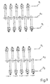
Bei der zweiten, besonders vorteilhaften Ausführungsform von Fig. 4 sind in der Reihe der Strecken D1, D2... die Sender S1, S2... abwechslungsweise von der ersten oder zweiten Art. Ferner sind die Sender S1, S2 abwechslungsweise in Zweiergruppen auf der einen bzw. der anderen Seite angeordnet. Die Zweiergruppen sind durch Klammern angedeutet. Entsprechendes gilt auch für die Empfänger E1, E2,... Bei dieser Anordnung kann beispielsweise Streulicht des Senders S1 die benachbarten drei Empfänger E2, E3 und E4 nicht beeinflussen. Erst auf den Empfänger E5 könnte Streulicht vom Sender S1 fallen. Dies ist jedoch kaum der Fall, weil der Abstand von der Strecke D1 relativ gross ist. Etwaig auf den Empfänger E5 fallendes Streulicht ist aber in der Regel von so geringer Intensität, dass es keinen Störeinfluss besitzt.In the second, particularly advantageous embodiment of FIG. 4, in the series of lines D1, D2 ... the transmitters S1, S2 ... are alternately of the first or second type. Furthermore, the transmitters S1, S2 are alternately in groups of two arranged on one or the other side. The groups of two are indicated by brackets. The same also applies to the receivers E1, E2, ... With this arrangement, for example, scattered light from the transmitter S1 cannot influence the adjacent three receivers E2, E3 and E4. Stray light from the transmitter S1 could only fall onto the receiver E5. However, this is hardly the case because the distance from the distance D1 is relatively large. Scattered light that may fall on the receiver E5 is usually of such a low intensity that it has no interference.
Den gleichen Vorteil ergibt die Ausführungsform gemäss Fig. 5, wo in aufeinanderfolgenden Dtrecken D1, D2... die Sender bzw. Empfänger abwechslungsweise auf der einen und der anderen Seite angeordnet sind. Wiederum sind Zweiergruppen von Sendern und Empfängern vorgesehen, wobei in einer solchen Zweiergruppe die Sender und Empfänger von der gleichen Art sind. Die Zweiergruppen von Sendern und Empfängern sind abwechslungsweise von der ersten bzw. der zweiten Art, wie dies durch die senkrechten bzw. waagrechten Striche angezeigt wird.The embodiment according to FIG. 5 gives the same advantage, where in successive distances D1, D2 ... the transmitters or Receivers are arranged alternately on one side and the other. Again, groups of two transmitters and receivers are provided, the transmitters and receivers being of the same type in such a group of two. The groups of two transmitters and receivers are alternately of the first and the second type, as indicated by the vertical and horizontal lines.
Bei der Anordnung von Fig. 6 sind die ungeradzahligen Strecken in einer ersten Ebene P1 und die geradzahligen Strecken in einer zweiten Ebene P2 angeordnet, die sich in einem Abstand d parallel zur ersten Ebene erstreckt. Diese Anordnung ist praktisch, wenn die Gehäuse der Sender und Empfänger eine gemeinsame Befestigungsachse A1 bzw. A2 aufweisen.6, the odd-numbered lines are arranged in a first plane P1 and the even-numbered lines in a second plane P2, which extends parallel to the first plane at a distance d. This arrangement is practical if the housing of the transmitter and receiver have a common fastening axis A1 or A2.
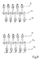
Bei der in Fig. 7 gezeigten Ausführungsform der Anordnung von Fig. 6 sind Sender S1, S2,... abwechslungsweise von der ersten oder zweiten Art. Ferner sind die Sender S1, S2 abwechslungsweise in Zweiergruppen auf der einen oder anderen Seite angeordnet. (Bei der schematischen Darstellung oben bzw. unten im Bild). Entsprechendes gilt auch für die Empfänger E1, E2,... Im Unterschied zu Fig. 4 sind aber die ungeradzahligen Sender und Empfänger in der Ebene P1 und die geradzahligen in der Ebene P2 angeordnet.In the embodiment of the arrangement of FIG. 6 shown in FIG. 7, transmitters S1, S2, ... are alternately of the first or second type. Furthermore, the transmitters S1, S2 are alternately arranged in groups of two on one side or the other. (In the schematic representation above or below in the picture). The same applies to the receivers E1, E2, ... In contrast to FIG. 4, however, the odd-numbered transmitters and receivers are arranged in the level P1 and the even-numbered ones in the level P2.
Bei der in Fig. 8 gezeigten Anordnung sind die Sender S1, S2,... abwechslungsweise auf der einen oder anderen Seite angeordnet. (Bei der schematischen Darstellung oben bzw. unten im Bild). Entsprechendes gilt auch für die Empfänger E1, E2,... Weiter sind Zweiergruppen von Sendern und Empfänger abwechslungsweise von der ersten bzw. zweiten Art. Im Unterschied zu Fig. 5 sind aber die ungeradzahligen Sender und Empfänger in der Ebene P1 und die geradzahligen in der Ebene P2 angeordnet.In the arrangement shown in Fig. 8, the transmitters S1, S2, ... are alternately arranged on one side or the other. (In the schematic representation above or below in the picture). The same also applies to the receivers E1, E2, ... Furthermore, groups of two transmitters and receivers are alternately of the first or second type. In contrast to FIG. 5, however, the odd-numbered transmitters and receivers are in level P1 and the even-numbered ones in the level P2 arranged.
In konstruktiver Hinsicht sind noch verschiedene Ausführungen der Einweg-Lichtschrankenanordnung möglich. So können die Sender und/oder Empfänger, die sich auf der einen bzw. der ande ren Seite befinden, jeweils in einem gemeinsamen Gehäuse angeordnet werden. Entsprechendes gilt auch für die Sender und/oder Empfänger, die sich in einer Ebene P1 oder P2 auf der einen oder anderen Seite befinden. Es ist auch möglich, die Einweg-Lichtschrankenanordnung in Form einer Gabellichtschrankenanordnung auszubilden. Bei einer solchen Ausbildung können Sender und Empfänger in einem gemeinsamen Gehäuse angeordnet sein.In terms of design, various designs of the one-way light barrier arrangement are still possible. So the transmitter and / or receiver, which are on one or the other ren side are each arranged in a common housing. The same applies to the transmitters and / or receivers, which are located on one level P1 or P2 on one side or the other. It is also possible to design the one-way light barrier arrangement in the form of a fork light barrier arrangement. With such a design, the transmitter and receiver can be arranged in a common housing.
Fig. 9 zeigt den Aufbau einer Einweg-Lichtschranke. Diese besteht aus dem Sender S und dem Empfänger E. Im Gehäuse 11 des Senders befindet sich ein stabilisiertes Netzgerät 12, das entweder für den Anschluss von Allstrom oder nur Wechselstrom oder nur Gleichstrom ausgelegt ist. Das Netzgerät 12 speist eine Senderschaltung 13, welche eine Strahlungsquelle 14 entweder mit Dauerlicht oder Pulslicht arbeiten lässt. Das von der Strahlungsquelle 14 ausgehende Licht wird je nach Anwendung gebündelt oder leicht divergent oder konvergent gemacht. Dazu dient die Frontlinse 15. Zwischen der Strahlungsquelle 14 und der Frontlinse 15 befindet sich ein lineares Polarisationsfilter 17. Ueber die Uebertragungsstrecke d gelangt das linear polarisierte Licht zum Empfänger E. Der Empfänger E besitzt ein Gehäuse 21, welches vorteilhaft gleich ausgebildet ist wie das Gehäuse 11 des Senders S. Hinter der Frontlinse 23 ist ein lineares Polarisationsfilter 25, welches die gleiche Polarisationsebene aufweist wie das Polarisationsfilter 17. Der Aufnahme des einfallenden Empfangslichtstrahls dient der fotoelektrische Wandler 27, dessen Ausgangssignal einem elektronischen Verstärker 29 zugeführt wird. An den Verstärker 29 ist eine elektronische Auswertestufe 31 angeschlossen, die vom stabilisierten Netzteil 33 versorgt wird. Der Ausgang 34, der eine Hell- oder Dunkelschaltung oder eine Antivalenzschaltung beinhalten kann, erfährt einen Signalwechsel, wenn der fotoelektrische Wandler eine Lichtstärke oberhalb eines vorgegebenen Schwellwertes empfängt.Fig. 9 shows the structure of a one-way light barrier. This consists of the transmitter S and the receiver E. In the
Claims (10)
Applications Claiming Priority (2)
| Application Number | Priority Date | Filing Date | Title |
|---|---|---|---|
| CH958/89 | 1989-03-15 | ||
| CH95889 | 1989-03-15 |
Publications (1)
| Publication Number | Publication Date |
|---|---|
| EP0388352A1 true EP0388352A1 (en) | 1990-09-19 |
Family
ID=4199132
Family Applications (1)
| Application Number | Title | Priority Date | Filing Date |
|---|---|---|---|
| EP90810116A Withdrawn EP0388352A1 (en) | 1989-03-15 | 1990-02-19 | One way light barrier arrangement |
Country Status (1)
| Country | Link |
|---|---|
| EP (1) | EP0388352A1 (en) |
Cited By (3)
| Publication number | Priority date | Publication date | Assignee | Title |
|---|---|---|---|---|
| EP0629370A1 (en) * | 1993-06-11 | 1994-12-21 | Solar Wide Industrial Ltd. | Monitoring device |
| FR2801400A1 (en) * | 1999-03-17 | 2001-05-25 | British Telecomm | Optical signal intruder detection system, having intense pulse source/target broadcast diffuser multiple photon rays providing and different position detectors detecting signal change |
| EP2012144A1 (en) * | 2007-07-05 | 2009-01-07 | Sick Ag | Light grid and method for operating a light grid |
Citations (3)
| Publication number | Priority date | Publication date | Assignee | Title |
|---|---|---|---|---|
| US3440427A (en) * | 1966-04-12 | 1969-04-22 | Philips Corp | Remote control system with a unitary cell bridge circuit |
| DE2014107A1 (en) * | 1970-03-24 | 1971-10-14 | Sarl Thevon Freres | Photoelectric barrier |
| EP0200186A2 (en) * | 1985-04-30 | 1986-11-05 | Cerberus Ag | Light barrier |
-
1990
- 1990-02-19 EP EP90810116A patent/EP0388352A1/en not_active Withdrawn
Patent Citations (3)
| Publication number | Priority date | Publication date | Assignee | Title |
|---|---|---|---|---|
| US3440427A (en) * | 1966-04-12 | 1969-04-22 | Philips Corp | Remote control system with a unitary cell bridge circuit |
| DE2014107A1 (en) * | 1970-03-24 | 1971-10-14 | Sarl Thevon Freres | Photoelectric barrier |
| EP0200186A2 (en) * | 1985-04-30 | 1986-11-05 | Cerberus Ag | Light barrier |
Cited By (4)
| Publication number | Priority date | Publication date | Assignee | Title |
|---|---|---|---|---|
| EP0629370A1 (en) * | 1993-06-11 | 1994-12-21 | Solar Wide Industrial Ltd. | Monitoring device |
| FR2801400A1 (en) * | 1999-03-17 | 2001-05-25 | British Telecomm | Optical signal intruder detection system, having intense pulse source/target broadcast diffuser multiple photon rays providing and different position detectors detecting signal change |
| FR2801401A1 (en) * | 1999-03-17 | 2001-05-25 | British Telecomm | DETECTION SYSTEM |
| EP2012144A1 (en) * | 2007-07-05 | 2009-01-07 | Sick Ag | Light grid and method for operating a light grid |
Similar Documents
| Publication | Publication Date | Title |
|---|---|---|
| DE60037178T2 (en) | LUMINAIRE, OPTICAL ELEMENT AND METHOD FOR LIGHTING AN OBJECT | |
| AT395914B (en) | PHOTOELECTRIC POSITION MEASURING DEVICE | |
| DE2501373C3 (en) | Arrangement for angle or length measurement | |
| DE10245495A1 (en) | Device for directing electromagnetic radiation | |
| DE2007840A1 (en) | Light barrier with luminescence diodes | |
| EP1003012B1 (en) | Optical position measuring arrangement | |
| DE3512708C1 (en) | Optoelectronic measuring stick | |
| DE3703423C2 (en) | ||
| DE10146639A1 (en) | Light grid with beam splitter | |
| DE2639802B2 (en) | Method and arrangement for non-contact optical measurement of an object cross-section | |
| EP2037296A2 (en) | Light grid | |
| DE202005010358U1 (en) | Optolectronic light barrier for security applications has frame with pairs of lamps separated by pairs of light sensors and has opposed frame with 45 degree mirrors set in two staggered rows | |
| DE102010044875A1 (en) | Illumination device for producing a linear intensity distribution in a working plane | |
| DE823053C (en) | Electromechanical transmitter | |
| EP0264027A2 (en) | Light curtain apparatus | |
| DE2539438C3 (en) | Radiation barrier | |
| EP0388352A1 (en) | One way light barrier arrangement | |
| DE3235253A1 (en) | OPTICAL COUPLING NETWORK FOR COUPLING MULTIPLE SUBSCRIBER TRANSMITTERS TO MULTIPLE SUBSCRIBE RECEIVERS BY MEANS OF OPTICAL STAR COUPLERS | |
| CH681749A5 (en) | ||
| DE202005017006U1 (en) | Light barrier, has electronic and opto-electronic components of one light barrier unit integrated in another unit, and optical fibers coupled at one of light emitters and receivers provided for positioning one monitoring section | |
| EP0281748A2 (en) | Reflective light barrier | |
| DE3013967A1 (en) | ADJUSTMENT ARRANGEMENT FOR LIGHT GRIDS | |
| DE1473965A1 (en) | Orientation device | |
| WO2003028262A1 (en) | Method and device for splitting and/or concentrating electromagnetic waves | |
| DE575553C (en) | Device for image scanning with a single hole spiral using several transmission channels |
Legal Events
| Date | Code | Title | Description |
|---|---|---|---|
| PUAI | Public reference made under article 153(3) epc to a published international application that has entered the european phase |
Free format text: ORIGINAL CODE: 0009012 |
|
| AK | Designated contracting states |
Kind code of ref document: A1 Designated state(s): AT BE CH DE DK ES FR GB GR IT LI LU NL SE |
|
| 17P | Request for examination filed |
Effective date: 19900917 |
|
| 17Q | First examination report despatched |
Effective date: 19930210 |
|
| STAA | Information on the status of an ep patent application or granted ep patent |
Free format text: STATUS: THE APPLICATION IS DEEMED TO BE WITHDRAWN |
|
| 18D | Application deemed to be withdrawn |
Effective date: 19940406 |