EP0386513A2 - Profile frame of an elastomer and method for manufacturing the same - Google Patents
Profile frame of an elastomer and method for manufacturing the same Download PDFInfo
- Publication number
- EP0386513A2 EP0386513A2 EP90103170A EP90103170A EP0386513A2 EP 0386513 A2 EP0386513 A2 EP 0386513A2 EP 90103170 A EP90103170 A EP 90103170A EP 90103170 A EP90103170 A EP 90103170A EP 0386513 A2 EP0386513 A2 EP 0386513A2
- Authority
- EP
- European Patent Office
- Prior art keywords
- profile
- section
- cross
- window
- sealing lip
- Prior art date
- Legal status (The legal status is an assumption and is not a legal conclusion. Google has not performed a legal analysis and makes no representation as to the accuracy of the status listed.)
- Granted
Links
- 238000004519 manufacturing process Methods 0.000 title claims abstract description 10
- 238000000034 method Methods 0.000 title claims description 9
- 229920001971 elastomer Polymers 0.000 title 1
- 239000000806 elastomer Substances 0.000 title 1
- 238000007789 sealing Methods 0.000 claims abstract description 49
- 238000004073 vulcanization Methods 0.000 claims abstract description 5
- 239000013536 elastomeric material Substances 0.000 claims abstract description 3
- 230000007704 transition Effects 0.000 claims description 10
- 230000003014 reinforcing effect Effects 0.000 claims description 7
- XAGFODPZIPBFFR-UHFFFAOYSA-N aluminium Chemical compound [Al] XAGFODPZIPBFFR-UHFFFAOYSA-N 0.000 claims description 6
- 229910052782 aluminium Inorganic materials 0.000 claims description 6
- 229910001220 stainless steel Inorganic materials 0.000 claims description 4
- 239000010935 stainless steel Substances 0.000 claims description 4
- 230000003247 decreasing effect Effects 0.000 claims description 3
- 230000002787 reinforcement Effects 0.000 description 4
- 238000005520 cutting process Methods 0.000 description 2
- 230000007423 decrease Effects 0.000 description 2
- 230000000694 effects Effects 0.000 description 2
- 238000001125 extrusion Methods 0.000 description 2
- 239000000463 material Substances 0.000 description 1
- 238000004904 shortening Methods 0.000 description 1
Images
Classifications
-
- B—PERFORMING OPERATIONS; TRANSPORTING
- B60—VEHICLES IN GENERAL
- B60J—WINDOWS, WINDSCREENS, NON-FIXED ROOFS, DOORS, OR SIMILAR DEVICES FOR VEHICLES; REMOVABLE EXTERNAL PROTECTIVE COVERINGS SPECIALLY ADAPTED FOR VEHICLES
- B60J10/00—Sealing arrangements
- B60J10/20—Sealing arrangements characterised by the shape
- B60J10/22—Sealing arrangements characterised by the shape having varying cross-section in the longitudinal direction
-
- B—PERFORMING OPERATIONS; TRANSPORTING
- B60—VEHICLES IN GENERAL
- B60J—WINDOWS, WINDSCREENS, NON-FIXED ROOFS, DOORS, OR SIMILAR DEVICES FOR VEHICLES; REMOVABLE EXTERNAL PROTECTIVE COVERINGS SPECIALLY ADAPTED FOR VEHICLES
- B60J10/00—Sealing arrangements
- B60J10/20—Sealing arrangements characterised by the shape
- B60J10/21—Sealing arrangements characterised by the shape having corner parts or bends
-
- B—PERFORMING OPERATIONS; TRANSPORTING
- B60—VEHICLES IN GENERAL
- B60J—WINDOWS, WINDSCREENS, NON-FIXED ROOFS, DOORS, OR SIMILAR DEVICES FOR VEHICLES; REMOVABLE EXTERNAL PROTECTIVE COVERINGS SPECIALLY ADAPTED FOR VEHICLES
- B60J10/00—Sealing arrangements
- B60J10/70—Sealing arrangements specially adapted for windows or windscreens
- B60J10/74—Sealing arrangements specially adapted for windows or windscreens for sliding window panes, e.g. sash guides
- B60J10/75—Sealing arrangements specially adapted for windows or windscreens for sliding window panes, e.g. sash guides for sealing the lower part of the panes
Definitions
- the invention relates to a profile frame made of elastomeric material, in particular for movable windows in motor vehicles, with a U-shaped clamping profile having a metallic reinforcing insert and a sealing lip projecting obliquely from the profile base, and a method for producing such profile frames.
- Such profile frames which are plugged onto the door frame surrounding the window in motor vehicles and are used on the one hand to guide the window and on the other hand to seal against rain, generally have a different sealing lip length on each window edge, this being the longest at the bottom edge of the window, since here too Sealing effect must be greatest.
- Such profile frames are usually produced in such a way that a separate profile of different cross-section is made for each edge, cut to length and finished at the window corners via vulcanized transition pieces to form a closed frame.
- Such a window guide profile is known for example from EP-A-0 171 821.
- the present invention is therefore based on the object of creating a profile frame and specifying corresponding production methods with which such a profile frame can be produced in a very simple manner in practically one operation.
- the window opening is surrounded on at least three sides by a one-piece, continuously extruded profile, the sealing lips of which have a different cross section at the profile sections of each window edge, each with a continuous transition in the window corners from one cross section to the next.
- the sealing lips can successively have a shorter length on the lower window edge, the window side edge and the upper window edge.
- the metallic reinforcement insert consists of aluminum or stainless steel and this is arranged within the clamping profile in such a way that it is guided on the outside of the profile leg as a decorative strip.
- the exposed areas of the reinforcement insert made of aluminum can be anodized after the final deformation of the frame.
- the invention provides that the profile surrounding the window opening on at least three sides is first required with a sealing lip in the form of the largest ten cross-section extruded continuously and then the sealing lip is cut back in sections in accordance with the required cross-section at the individual window edges before the vulcanization of the profile.
- the transition area can be formed in accordance with the length of the profile section running along an arc in the window corners.
- the free cross section of the extruder die can be continuously reduced in sections.
- the extruder pressure can be continuously adapted to the changing free cross-sections. However, it is also possible for excess extrudate to be recirculated as the cross section of the extruder die decreases.
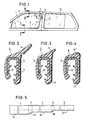
- the window 1 in the front door 2 of a motor vehicle is moved from a continuous profile frame 3 for guiding and sealing the window.
- This profile frame 2 is composed of three profile areas, namely the profile section 4 on the lower edge, the profile section 5 on the side edge of the B-pillar and the profile section 6 along the upper edge of the window 1, which are in the window corners via curved profile sections 7 and 8 stay in contact.
- the rear window 10 has a correspondingly composed profile frame 11.
- the profile frame 3 or 11 has a cross section with respect to the lower profile section, as is shown for the section line II-II in FIG. 2.
- this profile 4 consists of a U-shaped profile part 12 with a metallic reinforcing insert 13 in order to be firmly attached to a corresponding door flange.
- a sealing lip 14 projects laterally, which is relatively long in the profile section 4 at the lower edge of the window in order to achieve a good sealing effect against moisture.
- the profile frame 3 has the same base body 12 in all three profile sections 4, 5 and 6, but the length and cross section of the sealing lip 14 change, namely in the region of the profile section 5 according to FIG. 3 in a shorter one Sealing lip 14 'and in the region of the profile section 6 according to FIG. 4 only a short sealing lip extension 14 ".
- the profile frame 3 is now continuously produced in one piece in the following way:
- the profile is first extruded with a cross section as shown in Fig. 2, i.e. with a sealing lip 14 of the greatest length required.
- a cross section as shown in Fig. 2, i.e. with a sealing lip 14 of the greatest length required.
- the sealing lip 14 is cut back according to the continuous cut 15 to the sealing lip length 14 'with a corresponding cross section .
- the cutting device is then expediently extended again in order to subsequently obtain the next profile frame with the sealing lip 14 which is again complete for the profile section 4 and the subsequent cut-backs.
- flocking 17 can then be applied directly to the profile surface lying against the pane and the profile can finally be divided into the corresponding profile frame.
- the required cut-back is expediently carried out fully automatically, and - as can be seen in particular from FIG. 5 - there is a continuous transition corresponding to the cut edges 15 and 16 from one sealing lip length to the next following one. Since this cut-back is located in the area of the window corners, the appearance is also preserved and the appearance is more uniform than with separate corner sections.
- Fig. 6 shows a cross section through the profile section 20 for the lower edge of the window also in accordance with the cross section II-II of Fig. 1.
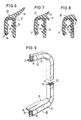
- the inner reinforcing insert 25 which suitably consists of aluminum or stainless steel, is guided so that it is located in the outer leg 26 of the profile 20 on the visible side thereof and thus additionally functions as a decorative strip 27.
- the lower end 28 is expediently returned to the material of the profile leg 26 in order to ensure a firm hold and to prevent peeling.
- the profile shown is also extruded with the largest required cross section, ie initially with the large obliquely projecting sealing lip 30 and the smaller sealing lip 31, which is only shown in broken lines protrudes diagonally downwards.
- the small sealing lip 31 can then be cut off from the associated profile section 20, so that a profile cross section results, as shown in full extension in FIG. 6.
- a cut back is then made for the upper side of the window in accordance with the profile cross section 22 according to FIG. 8, with only the downwardly directed sealing lip 31 remaining.
- Fig. 9 the finished molded profile frame in the area of the B-pillar with the subsequent profile sections 20 and 22 for the top and bottom of the window is then shown in perspective view.
- the cut back from the long sealing lip 30 to the shorter sealing lip 32 along the B-pillar can be seen particularly clearly in the course of the contour 33.
- the exposed area of the reinforcing insert 25, which extends over the entire circumference, can also be seen here as a decorative strip 27.
- the reinforcement insert 25 is made from stainless steel, post-treatment is not necessary because of the permanently shiny surface.
- the exposed trim strip area 27 can then be anodized on the profile frame after the profile frame has finally been deformed, in order to obtain a permanent and color-coordinated surface of this trim strip 27.
- the outlet cross section of the extruder die is set and readjusted in accordance with the required sealing lip cross section.
- the pressure or the speed of the extruder must then be reduced accordingly when the cross-section is reduced. It is also possible, however, to separate and recycle the excess extrudate portion as the cross section of the extruder die decreases, so that the pressure can then be kept constant.
Landscapes
- Engineering & Computer Science (AREA)
- Mechanical Engineering (AREA)
- Seal Device For Vehicle (AREA)
- Extrusion Moulding Of Plastics Or The Like (AREA)
Abstract
Description
Die Erfindung bezieht sich auf einen Profilrahmen aus elastomerem Material, insbesondere für bewegliche Scheiben in Kraftfahrzeugen, mit einem eine metallische Verstärkungseinlage aufweisenden, U-förmigen Klemmprofil und einer von der Profilbasis schräg abragenden Dichtlippe, sowie Verfahren zur Herstellung derartiger Profilrahmen.The invention relates to a profile frame made of elastomeric material, in particular for movable windows in motor vehicles, with a U-shaped clamping profile having a metallic reinforcing insert and a sealing lip projecting obliquely from the profile base, and a method for producing such profile frames.
Derartige Profilrahmen, die auf den das Fenster umgebenden Türrahmen in Kraftfahrzeugen aufgesteckt sind und einerseits zur Fensterführung und andererseits zur Abdichtung gegen Regen dienen, weisen im allgemeinen auf jeder Fensterkante eine unterschiedliche Dichtlippenlänge auf, wobei diese an der Fensterunterkante am längsten ist, da hier auch die Abdichtwirkung am größten sein muß. Üblicherweise werden derartige Profilrahmen derart hergestellt, daß für jede Kante ein gesondertes Profil unterschiedlichen Querschnittes gefertigt wird, auf Länge geschnitten und an den Fensterecken über einvulkanisierte Übergangsstücke zu einem geschlossenen Rahmen fertiggestellt wird.Such profile frames, which are plugged onto the door frame surrounding the window in motor vehicles and are used on the one hand to guide the window and on the other hand to seal against rain, generally have a different sealing lip length on each window edge, this being the longest at the bottom edge of the window, since here too Sealing effect must be greatest. Such profile frames are usually produced in such a way that a separate profile of different cross-section is made for each edge, cut to length and finished at the window corners via vulcanized transition pieces to form a closed frame.
Ein solches Fensterführungsprofil ist beispielsweise aus der EP-A-0 171 821 bekannt.Such a window guide profile is known for example from EP-A-0 171 821.
Ein solcher Profilrahmen ist in der Herstellung jedoch sehr aufwendig, da er eine große Anzahl von Arbeitsschritten erfordert, wodurch eine große Fehlerhäufigkeit und damit eine hohe Ausschußrate möglich ist.However, such a profile frame is very complex to produce, since it requires a large number of work steps, which results in a high frequency of errors and thus a high reject rate is possible.
Der vorliegenden Erfindung liegt daher die Aufgabe zugrunde, einen Profilrahmen zu schaffen und entsprechende Herstellungsverfahren anzugeben, mit denen auf sehr einfache Weise in praktisch einem Arbeitsgang ein solcher Profilrahmen hergestellt werden kann.The present invention is therefore based on the object of creating a profile frame and specifying corresponding production methods with which such a profile frame can be produced in a very simple manner in practically one operation.
Zur Lösung dieser Aufgabe ist erfindungsgemäß vorgesehen, daß die Fensteröffnung auf mindestens drei Seiten von einem einstückigen, kontinuierlich extrudierten Profil umgeben ist, dessen Dichtlippen an den Profilabschnitten jeder Fensterkante einen unterschiedlichen Querschnitt mit jeweils in den Fensterecken kontinuierlichen Übergang von einem Querschnitt auf den nachfolgenden aufweisen.To achieve this object, it is provided according to the invention that the window opening is surrounded on at least three sides by a one-piece, continuously extruded profile, the sealing lips of which have a different cross section at the profile sections of each window edge, each with a continuous transition in the window corners from one cross section to the next.
Dabei können die Dichtlippen aufeinanderfolgend auf Fensterunterkante, Fensterseitenkante und Fensteroberkante jeweils eine kürzere Länge aufweisen.The sealing lips can successively have a shorter length on the lower window edge, the window side edge and the upper window edge.
Bsonders vorteilhaft ist es, wenn bei einem solchen Profilrahmen die metallische Verstärkungseinlage aus Aluminium oder rostfreiem Stahl besteht und diese innerhalb des Klemmprofils so angeordnet ist, daß sie auf der Sicht-Außenseite außen am Profilschenkel als Zierleiste geführt ist.It is particularly advantageous if, with such a profile frame, the metallic reinforcement insert consists of aluminum or stainless steel and this is arranged within the clamping profile in such a way that it is guided on the outside of the profile leg as a decorative strip.
Dabei können die freiliegenden Bereiche der Verstärkungseinlage aus Aluminium nach der Endverformung des Rahmens eloxiert sein.The exposed areas of the reinforcement insert made of aluminum can be anodized after the final deformation of the frame.
Bei einem Verfahren zur Herstellung derartiger Profilrahmen ist erfindungsgemäß vorgesehen, daß das die Fensteröffnung auf mindestens drei Seiten umgebende Profil zunächst mit einer Dichtlippe in Form des größten geforder ten Querschnittes fortlaufend einstückig extrudiert und anschließend vor der Ausvulkanisation des Profils die Dichtlippe abschnittsweise entsprechend dem jeweils geforderten Querschnitt an den einzelnen Fensterkanten zurückgeschnitten wird.In a method for producing such profile frames, the invention provides that the profile surrounding the window opening on at least three sides is first required with a sealing lip in the form of the largest ten cross-section extruded continuously and then the sealing lip is cut back in sections in accordance with the required cross-section at the individual window edges before the vulcanization of the profile.
Mit einem derartigen Verfahren ist es also auf einfache Weise möglich, einen das Fenster auf drei Seiten umgebenen Profilrahmen aus einem Stück herzustellen, wobei die Übergänge auf unterschiedliche Dichtlippenlängen kontinuierlich in einem Arbeitsgang geschaffen werden können, ohne daß gesonderte Zwischenstücke einvulkanisiert werden müssen.With such a method it is thus possible in a simple manner to produce a profile frame surrounding the window on three sides, the transitions to different sealing lip lengths being able to be created continuously in one work step without having to vulcanize in separate intermediate pieces.
Zweckmäßig ist es dabei, wenn die Übergänge der Profilkontur von einem Dichtlippenquerschnitt auf den nächsten im Bereich der Fensterecken mittels eines einen stetig abnehmenden Querschnitt bewirkenden Schnittes erfolgt.It is expedient here if the transitions of the profile contour from one sealing lip cross section to the next in the area of the window corners take place by means of a section which causes a continuously decreasing cross section.
Der Übergangsbereich kann dabei entsprechend der Länge des entlang einem Kreisbogen verlaufenden Profilabschnittes in den Fensterecken ausgebildet werden.The transition area can be formed in accordance with the length of the profile section running along an arc in the window corners.
Bei einem weiteren Verfahren zur Herstellung eines solchen Profilrahmens ist erfindungsgemäß vorgesehen, daß das die Fensteröffnung auf mindestens drei Seiten einstückig umgebende Profil derart extrudiert wird, daß der freie Austrittsquerschnitt des Extrudermundstückes jeweils entsprechend dem geforderten Dichtlippenquerschnitt eingestellt und nachgeregelt wird.In a further method for producing such a profile frame, it is provided according to the invention that the profile surrounding the window opening in one piece on at least three sides is extruded in such a way that the free outlet cross section of the extruder die is adjusted and readjusted in accordance with the required sealing lip cross section.
Damit ist es also möglich, bereits bei der Extrusion die gewünschten unterschiedlichen Dichtlippenlängen bzw. Dichtlippenquerschnitte zu erhalten.It is therefore possible to obtain the desired different sealing lip lengths or sealing lip cross sections during extrusion.
Der freie Querschnitt des Extrudermundstückes kann dabei abschnittsweise kontinuierlich verringert werden.The free cross section of the extruder die can be continuously reduced in sections.
Dabei kann der Extruderdruck kontinuierlich an die sich verändernden freien Querschnitte angepaßt werden. Es ist aber auch möglich, daß bei sich verringerndem Querschnitt des Extrudermundstückes überschüssige Extrudatteilmenge rezirkuliert wird.The extruder pressure can be continuously adapted to the changing free cross-sections. However, it is also possible for excess extrudate to be recirculated as the cross section of the extruder die decreases.
Anhand einer schematischen Zeichnung sind Aufbau und Funktionsweise von Ausführungsbeispielen nach der Erfindung näher erläutert. Dabei zeigen
- Fig. 1 eine Seitenansicht des Fensterbereichs eines Kraftfahrzeuges,
- Fig. 2 einen Querschnitt durch einen Profilrahmen im Bereich der Fensterunterkante entsprechend der Schnittlinie II-II nach Fig. 1,
- Fig. 3 einen Querschnitt durch den Profilrahmen im Bereich der B-Säule entsprechend der Schnittlinie III-III nach Fig. 1,
- Fig. 4 einen Querschnitt durch den Profilrahmen an der Oberkante des Fensters entsprechend der Schnittlinie IV-IV nach Fig. 1,
- Fig. 5 eine Aufsicht in verkürzter Darstellung auf den Profilrahmen mit unterschiedlicher Dichtlippenlänge entsprechend den
Figuren 2 bis 4, - Fig. 6 - 8 entsprechende Querschnitte durch ein ähnliches Profil mit teilweise freiliegender Verstärkungs einlage als Zierleiste und
- Fig. 9 eine perspektivische Teilansicht eines Profils entsprechend Fig. 6 bis 8.
- 1 is a side view of the window area of a motor vehicle,
- 2 shows a cross section through a profile frame in the area of the lower window edge in accordance with the section line II-II according to FIG. 1,
- 3 shows a cross section through the profile frame in the area of the B-pillar according to section line III-III according to FIG. 1,
- 4 shows a cross section through the profile frame on the upper edge of the window corresponding to section line IV-IV according to FIG. 1,
- 5 is a top view in a shortened representation of the profile frame with different sealing lip length corresponding to FIGS. 2 to 4,
- 6 - 8 corresponding cross-sections through a similar profile with partially exposed reinforcement insert as a decorative strip and
- 9 is a partial perspective view of a profile corresponding to FIGS. 6 to 8.
Wie man aus Fig. 1 ersieht, ist das Fenster 1 in der Vordertür 2 eines Kraftfahrzeuges von einem durchgehenden Profilrahmen 3 zur Führung und Abdichtung der Scheibe umzogen. Dieser Profilrahmen 2 setzt sich aus drei Profilbereichen, nämlich dem Profilabschnitt 4 an der Unterkante, dem Profilabschnitt 5 an der Seitenkante der B-Säule und dem Profilabschnitt 6 entlang der Oberkante des Fensters 1 zusammen, die in den Fensterecken über gebogene Profilabschnitte 7 und 8 miteinander in Verbindung stehen. Das Hinterfenster 10 weist dabei einen entsprechend zusammengesetzten Profilrahmen 11 auf.As can be seen from Fig. 1, the window 1 in the
Der Profilrahmen 3 bzw. 11 hat bezüglich des unteren Profilabschnitts einen Querschnitt, wie er für die Schnittlinie II-II in Fig. 2 dargestellt ist. Danach besteht dieses Profil 4 aus einem U-förmigen Profilteil 12 mit einer metallischen Verstärkungseinlage 13, um damit festhaftend auf einen entsprechenden Türflansch aufgesteckt zu werden. Von diesem U-förmigen Profilbereich 12 ragt seitlich eine Dichtlippe 14 ab, die bei dem Profilabschnitt 4 an der Unterkante des Fensters relativ lang ist, um eine gute Dichtwirkung gegen Feuchtigkeit zu erreichen.The
Wie man aus Fig. 1 und den entsprechenden Schnitten nach Fig. 2, 3 und 4 ersieht, weist der Profilrahmen 3 zwar in allen drei Profilabschnitten 4, 5 und 6 den gleichen Grundkörper 12 auf, jedoch ändert sich Länge und Querschnitt der Dichtlippe 14, und zwar weist diese im Bereich des Profilabschnitts 5 nach Fig. 3 in eine kürzere Dichtlippe 14′ und im Bereich des Profilabschnitts 6 entsprechend Fig. 4 nur noch einen kurzen Dichtlippenansatz 14" auf.1 and the corresponding sections according to FIGS. 2, 3 and 4, the
Nach der vorliegenden Erfindung wird nun der Profilrahmen 3 einstückig fortlaufend hergestellt und zwar auf folgende Weise:According to the present invention, the
Das Profil wird zunächst mit einem Querschnitt extrudiert, wie er in Fig. 2 dargestellt ist, d.h. mit einer Dichtlippe 14 von der größten erforderlichen Länge. Unmittelbar anschließend an die Extrusion, d.h. noch vor der Vulkanisation des Profils, wird nach Erreichen der vorgegebenen Länge für den Profilabschnitt 4 - wie in der Aufsicht auf das Profil nach Fig. 5 zu sehen ist - die Dichtlippe 14 entsprechend dem stetigen Schnitt 15 auf die Dichtlippenlänge 14′ mit entsprechendem Querschnitt zurückgeschnitten. Die Verkürzung der Dichtlippe 14 auf die Dichtlippe 14′ erfolgt dabei allein über einen Bereich der unteren Fensterecke, wie er dem Profilabschnitt 7 entspricht.The profile is first extruded with a cross section as shown in Fig. 2, i.e. with a
Nach Erreichen der erforderlichen Länge für den Profilabschnitt 5 erfolgt ein weiterer Rückschnitt 16 auf die Dichtlippenlänge 14" für den oberen Profilabschnitt 6. Dieser Rückschnitt 16 liegt dabei in der oberen Profilecke 8.After the required length for the
Nach Erreichen der erforderlichen Länge für den Profilabschnitt 6 wird dann zweckmäßigerweise die Schneidvorrichtung wieder ausgefahren, um anschließend den nächsten Profilrahmen mit der für den Profilabschnitt 4 wieder vollständigen Dichtlippe 14 und den nachfolgenden Rückschnitten zu erhalten.After the required length for the
Nach anschließender Ausvulkanisation des durchlaufenden Profils kann dann unmittelbar auf die an der Scheibe anliegenden Profilfläche eine Beflockung 17 aufgebracht und schließlich das Profil in die entsprechenden Profilrahmen abgeteilt werden.After subsequent vulcanization of the continuous profile, flocking 17 can then be applied directly to the profile surface lying against the pane and the profile can finally be divided into the corresponding profile frame.
Der jeweils erforderliche Rückschnitt erfolgt dabei zweckmäßigerweise vollautomatisch, wobei - wie insbesondere aus Fig. 5 zu erkennen ist - ein stetiger Übergang entsprechend der Schnittkanten 15 und 16 von einer Dichtlippenlänge auf die nächstnachfolgende vorgesehen ist. Da dieser Rückschnitt jeweils im Bereich der Fensterecken liegt, ist damit auch die Optik gewahrt und es ergibt sich ein einheitlicheres Erscheinungsbild als mit gesondert zwischengesetzten Eckabschnitten.The required cut-back is expediently carried out fully automatically, and - as can be seen in particular from FIG. 5 - there is a continuous transition corresponding to the
Eine weitere Ausgestaltungsmöglichkeit eines solchen Profilrahmens ist in den Fig. 6, 7 und 8 dargestellt.Another possible design of such a profile frame is shown in FIGS. 6, 7 and 8.
Fig. 6 zeigt dabei einen Querschnitt durch den Profilabschnitt 20 für die Unterkante des Fensters auch entsprechend dem Querschnitt II-II nach Fig. 1. Dabei ist zunächst die innenliegende Verstärkungseinlage 25, die zweckmäßigerweise aus Aluminium oder rostfreiem Stahl besteht, so geführt, daß sie im außenliegenden Schenkel 26 des Profils 20 auf dessen Sichtseite außen liegt und damit zusätzlich als Zierleiste 27 fungiert. Das untere Ende 28 ist dabei zweckmäßigerweise in das Material des Profilschenkels 26 zurückgeführt, um einen festen Halt zu gewährleisten und ein Abschälen zu verhindern.Fig. 6 shows a cross section through the
Das dargestellte Profil wird ebenfalls mit dem größten erforderlichen Querschnitt extrudiert, d.h. zunächst mit der großen schräg abragenden Dichtlippe 30 und der kleineren, nur gestrichelt dargestellten Dichtlippe 31, die schräg nach unten abragt. Für die Unterseite des Fensters kann dann von dem zugehörigen Profilabschnitt 20 die kleine Dichtlippe 31 abgeschnitten werden, so daß sich ein Profilquerschnitt ergibt, wie er in Fig. 6 voll ausgezogen dargestellt ist.The profile shown is also extruded with the largest required cross section, ie initially with the large obliquely projecting
Im Übergangsbereich zum nachfolgenden Profilabschnitt 21 entlang der B-Säule entsprechend Fig. 7 wird dann die große Dichtlippe 30 aus Fig. 6 auf eine kleinere Dichtlippe 32 zurückgeschnitten und die ursprünglich extrudierte, nach unten abragende Dichtlippe 31 stehengelassen.7, the
Für die Oberseite des Fensters erfolgt dann ein Rückschnitt entsprechend dem Profilquerschnitt 22 nach Fig. 8, wobei jetzt nur noch die nach unten gerichtete Dichtlippe 31 stehenbleibt.A cut back is then made for the upper side of the window in accordance with the
In Fig. 9 ist in perspektivischer Ansicht dann der fertig geformte Profilrahmen im Breich der B-Säule mit den anschließenden Profilabschnitten 20 und 22 für Ober- und Unterseite des Fensters gezeigt. Besonders deutlich erkennt man dabei am Verlauf der Kontur 33 den Rückschnitt von der langen Dichtlippe 30 auf die kürzere Dichtlippe 32 entlang der B-Säule. Hier ist auch der sich über den gesamten Umfang erstreckende freiliegende Bereich der Verstärkungseinlage 25 als Zierleiste 27 zu erkennen. Bei einer Herstellung der Verstärkungseinlage 25 aus rostfreiem Stahl ist eine Nachbehandlung wegen der dauerhaft glänzenden Oberfläche nicht erforderlich. Bei einer Herstellung aus Aluminium kann jedoch dann der freiliegende Zierleistenbereich 27 nach abschließender Verformung des Profilrahmens noch am Profilrahmen eloxiert werden, um damit eine dauerhafte und farbmäßig abgestimmte Oberfläche dieser Zierleist 27 zu erhalten.In Fig. 9, the finished molded profile frame in the area of the B-pillar with the
Anstelle eines automatischen Zurückschneidens der Dichtlippe nach der Extrusion des Profils und vor seiner endgültigen Vulkanisation ist es aber auch möglich, das Profil gleich mit der entsprechenden Kontur zu extrudieren. Dazu wird der Austrittsquerschnitt des Extrudermundstückes jeweils entsprechend dem geforderten Dichtlippenquerschnitt eingestellt und nachgeregelt. Dabei wird zweckmäßigerweise jeweils mit dem größten Profilquerschnitt angefangen und an den jeweiligen Übergangsbereichen der Austritsquerschnitt des Extrudermundstückes kontinuierlich so weit zugefahren, bis der nachfolgende Profilquerschnitt erreicht ist. Damit ergebt sich dann ebenfalls ein Profilverlauf, wie er in Fig. 5 dargestellt ist.Instead of automatically cutting back the sealing lip after extruding the profile and before it is finally vulcanized, it is also possible to extrude the profile with the appropriate contour. For this purpose, the outlet cross section of the extruder die is set and readjusted in accordance with the required sealing lip cross section. In this case, it is expedient to start with the largest profile cross section in each case and at the respective transition regions the exit cross section of the extruder die is continuously closed until the subsequent profile cross section is reached. This then also results in a profile profile, as shown in FIG. 5.
Um eine gleichmäßige Kontur des Profils zu erhalten, muß bei der Querschnittsverringerung dann auch entsprechend der Druck bzw. die Drehzahl des Extruders zurückgefahren werden. Es ist aber auch möglich, die bei sich verringerndem Querschnitt des Extrudermundstückes überschüssige Extrudatteilmenge abzutrennen und zurückzuführen, so daß dann mit konstantem Druck gefahren werden kann.In order to obtain a uniform contour of the profile, the pressure or the speed of the extruder must then be reduced accordingly when the cross-section is reduced. It is also possible, however, to separate and recycle the excess extrudate portion as the cross section of the extruder die decreases, so that the pressure can then be kept constant.
Mit den beschriebenen Verfahren ist es also auf einfache Weise möglich, einen Profilrahmen mit unterschiedlicher Dichtlippenlänge auf den verschiedenen Profilbereichen entlang des Fensterausschnittes zu erhalten. Gleichzeitig kann dabei in einem Arbeitsgang auch eine integrale Zierleiste erhalten werden, ohne daß dafür zusätzliche Manipulationen erforderlich wären.With the methods described, it is therefore possible in a simple manner to obtain a profile frame with different sealing lip lengths on the different profile areas along the window cutout. At the same time, an integral trim strip can also be obtained in one work step without additional manipulations being required.
Claims (11)
Applications Claiming Priority (4)
| Application Number | Priority Date | Filing Date | Title |
|---|---|---|---|
| DE3907691 | 1989-03-09 | ||
| DE3907691 | 1989-03-09 | ||
| DE4002026A DE4002026A1 (en) | 1989-03-09 | 1990-01-24 | PROFILE FRAME MADE OF ELASTOMERIC MATERIAL AND METHOD FOR THE PRODUCTION THEREOF |
| DE4002026 | 1990-01-24 |
Publications (3)
| Publication Number | Publication Date |
|---|---|
| EP0386513A2 true EP0386513A2 (en) | 1990-09-12 |
| EP0386513A3 EP0386513A3 (en) | 1992-02-26 |
| EP0386513B1 EP0386513B1 (en) | 1994-06-01 |
Family
ID=25878643
Family Applications (1)
| Application Number | Title | Priority Date | Filing Date |
|---|---|---|---|
| EP90103170A Expired - Lifetime EP0386513B1 (en) | 1989-03-09 | 1990-02-19 | Profile frame of an elastomer and method for manufacturing the same |
Country Status (3)
| Country | Link |
|---|---|
| EP (1) | EP0386513B1 (en) |
| DE (2) | DE4002026A1 (en) |
| ES (1) | ES2054118T3 (en) |
Cited By (9)
| Publication number | Priority date | Publication date | Assignee | Title |
|---|---|---|---|---|
| EP0625446A1 (en) * | 1993-05-20 | 1994-11-23 | Draftex Industries Limited | Sealing, trimming and finishing strips |
| FR2724602A1 (en) * | 1994-09-21 | 1996-03-22 | Mesnel Sa Ets | EXTRUDED ELASTOMER PROFILE, WITH METAL REINFORCING, FOR MOTOR VEHICLE, AND PROCESS FOR PRODUCING THE SAME |
| GB2334990A (en) * | 1998-03-03 | 1999-09-08 | Draftex Ind Ltd | A sealing strip for a sunroof comprising a water-directing lip along part of its length |
| WO1999048714A1 (en) | 1997-03-19 | 1999-09-30 | Metzeler Automotive Profiles Gmbh | Sealing profile for motor vehicles |
| US6612074B1 (en) | 1999-05-27 | 2003-09-02 | Schlegel Corporation | Glass run surround cap |
| DE102008026922A1 (en) * | 2008-06-05 | 2009-12-10 | Henniges Automotive Gmbh & Co. Kg | Decorative profile, in particular for the window region of a motor vehicle |
| FR2961161A1 (en) * | 2010-06-14 | 2011-12-16 | Peugeot Citroen Automobiles Sa | Seal joint for sealing between half-foot type and frameless type swiveling side door assembled on foot of rear opening assembly of body shell of motor vehicle, has section equipped with sealing lip directed according to direction |
| CN107791801A (en) * | 2017-11-16 | 2018-03-13 | 建新赵氏集团有限公司 | Cut for water outside the integral type variable cross-section of car rear window |
| DE102012002146B4 (en) | 2012-02-04 | 2022-02-17 | Audi Ag | window arrangement |
Families Citing this family (4)
| Publication number | Priority date | Publication date | Assignee | Title |
|---|---|---|---|---|
| DE19632843C1 (en) * | 1996-08-14 | 1997-09-25 | Metzeler Automotive Profiles | Profile frame for a moving window |
| JP2006502048A (en) | 2002-10-02 | 2006-01-19 | ジーディーエックス・ノース・アメリカ・インコーポレーテッド | Sealing, trimming or guiding strip |
| US8493081B2 (en) | 2009-12-08 | 2013-07-23 | Magna Closures Inc. | Wide activation angle pinch sensor section and sensor hook-on attachment principle |
| US9234979B2 (en) | 2009-12-08 | 2016-01-12 | Magna Closures Inc. | Wide activation angle pinch sensor section |
Citations (4)
| Publication number | Priority date | Publication date | Assignee | Title |
|---|---|---|---|---|
| BE551617A (en) * | ||||
| FR2477998A1 (en) * | 1980-03-11 | 1981-09-18 | Nissan Motor | RIGOLE FOR AUTOMOTIVE VEHICLE DOOR ICE |
| US4291076A (en) * | 1979-04-09 | 1981-09-22 | Inoue Gomu Kogyo Kabushiki Kaisha | Trim molding strips for a vehicle |
| EP0171821A1 (en) * | 1984-08-21 | 1986-02-19 | Toyota Jidosha Kabushiki Kaisha | Door glass runs in motor vehicle |
-
1990
- 1990-01-24 DE DE4002026A patent/DE4002026A1/en not_active Withdrawn
- 1990-02-19 DE DE59005856T patent/DE59005856D1/en not_active Expired - Fee Related
- 1990-02-19 EP EP90103170A patent/EP0386513B1/en not_active Expired - Lifetime
- 1990-02-19 ES ES90103170T patent/ES2054118T3/en not_active Expired - Lifetime
Patent Citations (4)
| Publication number | Priority date | Publication date | Assignee | Title |
|---|---|---|---|---|
| BE551617A (en) * | ||||
| US4291076A (en) * | 1979-04-09 | 1981-09-22 | Inoue Gomu Kogyo Kabushiki Kaisha | Trim molding strips for a vehicle |
| FR2477998A1 (en) * | 1980-03-11 | 1981-09-18 | Nissan Motor | RIGOLE FOR AUTOMOTIVE VEHICLE DOOR ICE |
| EP0171821A1 (en) * | 1984-08-21 | 1986-02-19 | Toyota Jidosha Kabushiki Kaisha | Door glass runs in motor vehicle |
Cited By (12)
| Publication number | Priority date | Publication date | Assignee | Title |
|---|---|---|---|---|
| EP0625446A1 (en) * | 1993-05-20 | 1994-11-23 | Draftex Industries Limited | Sealing, trimming and finishing strips |
| FR2724602A1 (en) * | 1994-09-21 | 1996-03-22 | Mesnel Sa Ets | EXTRUDED ELASTOMER PROFILE, WITH METAL REINFORCING, FOR MOTOR VEHICLE, AND PROCESS FOR PRODUCING THE SAME |
| EP0703116A1 (en) * | 1994-09-21 | 1996-03-27 | Etablissements Mesnel Societe Anonyme Dite : | Extruded elastomer profile with metallic armature for vehicles and methode for its production |
| WO1999048714A1 (en) | 1997-03-19 | 1999-09-30 | Metzeler Automotive Profiles Gmbh | Sealing profile for motor vehicles |
| CN1098173C (en) * | 1997-03-19 | 2003-01-08 | 梅策勒汽车型材有限公司 | Sealing profile for motor vehicle |
| GB2334990A (en) * | 1998-03-03 | 1999-09-08 | Draftex Ind Ltd | A sealing strip for a sunroof comprising a water-directing lip along part of its length |
| US6612074B1 (en) | 1999-05-27 | 2003-09-02 | Schlegel Corporation | Glass run surround cap |
| DE102008026922A1 (en) * | 2008-06-05 | 2009-12-10 | Henniges Automotive Gmbh & Co. Kg | Decorative profile, in particular for the window region of a motor vehicle |
| FR2961161A1 (en) * | 2010-06-14 | 2011-12-16 | Peugeot Citroen Automobiles Sa | Seal joint for sealing between half-foot type and frameless type swiveling side door assembled on foot of rear opening assembly of body shell of motor vehicle, has section equipped with sealing lip directed according to direction |
| DE102012002146B4 (en) | 2012-02-04 | 2022-02-17 | Audi Ag | window arrangement |
| CN107791801A (en) * | 2017-11-16 | 2018-03-13 | 建新赵氏集团有限公司 | Cut for water outside the integral type variable cross-section of car rear window |
| CN107791801B (en) * | 2017-11-16 | 2023-09-22 | 建新赵氏科技股份有限公司 | Integrated variable cross-section external water cutter for rear window of car |
Also Published As
| Publication number | Publication date |
|---|---|
| DE4002026A1 (en) | 1990-09-13 |
| ES2054118T3 (en) | 1994-08-01 |
| EP0386513A3 (en) | 1992-02-26 |
| DE59005856D1 (en) | 1994-07-07 |
| EP0386513B1 (en) | 1994-06-01 |
Similar Documents
| Publication | Publication Date | Title |
|---|---|---|
| DE19517756B4 (en) | Method for producing a rail for a door frame for an automobile | |
| DE69508132T2 (en) | Sealing strip arrangement | |
| DE69032289T2 (en) | One-piece sealing strip | |
| DE68911421T2 (en) | Window frame system for motor vehicles. | |
| DE69100989T2 (en) | Process for producing a molded part for car windscreens. | |
| DE69207684T2 (en) | Sealing strip with expandable width | |
| DE19939725C2 (en) | Vehicle convertible roof structure | |
| DE3305088C2 (en) | ||
| DE3843057A1 (en) | GASKET PROFILE BAR | |
| EP0386513B1 (en) | Profile frame of an elastomer and method for manufacturing the same | |
| DE3929159C2 (en) | Sealing profile strip | |
| DE3609099A1 (en) | SEALING STRIP FOR MOTOR VEHICLES AND METHOD AND DEVICE FOR THEIR PRODUCTION | |
| DE69717944T2 (en) | Flange cover with a smooth outer surface | |
| DE69005987T2 (en) | Seal, device and method for their manufacture. | |
| DE2734971A1 (en) | DOOR SEAL FOR MOTOR VEHICLES | |
| DE4034432A1 (en) | Elastomer extrusion | |
| DE69309195T2 (en) | Extruded hollow profiles and manufacturing processes | |
| EP0081093A1 (en) | Extruder | |
| DE10152951A1 (en) | Sealing system for use between plastic profile and aluminum extrusion on car sun roof frame comprises seal which is cast into groove in plastic profile | |
| DE3729108A1 (en) | PROFILE BAR | |
| DE19632843C1 (en) | Profile frame for a moving window | |
| DE19501389C1 (en) | Roof edging for sliding or lifting roof of motor vehicles | |
| DE4335101A1 (en) | Window form part for vehicle - has main section arranged between vehicle body and vehicle window and decorative section connected to main section over its length | |
| DE202007004123U1 (en) | Extruded vacuum sealed or end plate for fastening to motor vehicle, has front and rear end sections and middle section in which, over short longitudinal extension of profile carrier border, no clamping lips are provided in retaining channel | |
| DE69301552T2 (en) | Sealing and guiding device |
Legal Events
| Date | Code | Title | Description |
|---|---|---|---|
| PUAI | Public reference made under article 153(3) epc to a published international application that has entered the european phase |
Free format text: ORIGINAL CODE: 0009012 |
|
| 17P | Request for examination filed |
Effective date: 19900219 |
|
| AK | Designated contracting states |
Kind code of ref document: A2 Designated state(s): DE ES FR GB IT SE |
|
| RAP1 | Party data changed (applicant data changed or rights of an application transferred) |
Owner name: METZELER AUTOMOTIVE PROFILES GMBH |
|
| PUAL | Search report despatched |
Free format text: ORIGINAL CODE: 0009013 |
|
| AK | Designated contracting states |
Kind code of ref document: A3 Designated state(s): DE ES FR GB IT SE |
|
| 17Q | First examination report despatched |
Effective date: 19930616 |
|
| GRAA | (expected) grant |
Free format text: ORIGINAL CODE: 0009210 |
|
| AK | Designated contracting states |
Kind code of ref document: B1 Designated state(s): DE ES FR GB IT SE |
|
| REF | Corresponds to: |
Ref document number: 59005856 Country of ref document: DE Date of ref document: 19940707 |
|
| ITF | It: translation for a ep patent filed | ||
| REG | Reference to a national code |
Ref country code: ES Ref legal event code: FG2A Ref document number: 2054118 Country of ref document: ES Kind code of ref document: T3 |
|
| GBT | Gb: translation of ep patent filed (gb section 77(6)(a)/1977) |
Effective date: 19940712 |
|
| ET | Fr: translation filed | ||
| EAL | Se: european patent in force in sweden |
Ref document number: 90103170.8 |
|
| PLBE | No opposition filed within time limit |
Free format text: ORIGINAL CODE: 0009261 |
|
| STAA | Information on the status of an ep patent application or granted ep patent |
Free format text: STATUS: NO OPPOSITION FILED WITHIN TIME LIMIT |
|
| 26N | No opposition filed | ||
| PGFP | Annual fee paid to national office [announced via postgrant information from national office to epo] |
Ref country code: GB Payment date: 20010205 Year of fee payment: 12 |
|
| PGFP | Annual fee paid to national office [announced via postgrant information from national office to epo] |
Ref country code: FR Payment date: 20010215 Year of fee payment: 12 |
|
| PGFP | Annual fee paid to national office [announced via postgrant information from national office to epo] |
Ref country code: SE Payment date: 20010221 Year of fee payment: 12 Ref country code: ES Payment date: 20010221 Year of fee payment: 12 |
|
| REG | Reference to a national code |
Ref country code: GB Ref legal event code: IF02 |
|
| PG25 | Lapsed in a contracting state [announced via postgrant information from national office to epo] |
Ref country code: GB Free format text: LAPSE BECAUSE OF NON-PAYMENT OF DUE FEES Effective date: 20020219 |
|
| PG25 | Lapsed in a contracting state [announced via postgrant information from national office to epo] |
Ref country code: SE Free format text: LAPSE BECAUSE OF NON-PAYMENT OF DUE FEES Effective date: 20020220 Ref country code: ES Free format text: LAPSE BECAUSE OF NON-PAYMENT OF DUE FEES Effective date: 20020220 |
|
| EUG | Se: european patent has lapsed |
Ref document number: 90103170.8 |
|
| GBPC | Gb: european patent ceased through non-payment of renewal fee |
Effective date: 20020219 |
|
| PG25 | Lapsed in a contracting state [announced via postgrant information from national office to epo] |
Ref country code: FR Free format text: LAPSE BECAUSE OF NON-PAYMENT OF DUE FEES Effective date: 20021031 |
|
| REG | Reference to a national code |
Ref country code: FR Ref legal event code: ST |
|
| REG | Reference to a national code |
Ref country code: ES Ref legal event code: FD2A Effective date: 20030922 |
|
| PG25 | Lapsed in a contracting state [announced via postgrant information from national office to epo] |
Ref country code: IT Free format text: LAPSE BECAUSE OF NON-PAYMENT OF DUE FEES;WARNING: LAPSES OF ITALIAN PATENTS WITH EFFECTIVE DATE BEFORE 2007 MAY HAVE OCCURRED AT ANY TIME BEFORE 2007. THE CORRECT EFFECTIVE DATE MAY BE DIFFERENT FROM THE ONE RECORDED. Effective date: 20050219 |
|
| PGFP | Annual fee paid to national office [announced via postgrant information from national office to epo] |
Ref country code: DE Payment date: 20050224 Year of fee payment: 16 |
|
| PG25 | Lapsed in a contracting state [announced via postgrant information from national office to epo] |
Ref country code: DE Free format text: LAPSE BECAUSE OF NON-PAYMENT OF DUE FEES Effective date: 20060901 |