EP0386329B1 - Cylinder block - Google Patents
Cylinder block Download PDFInfo
- Publication number
- EP0386329B1 EP0386329B1 EP89122254A EP89122254A EP0386329B1 EP 0386329 B1 EP0386329 B1 EP 0386329B1 EP 89122254 A EP89122254 A EP 89122254A EP 89122254 A EP89122254 A EP 89122254A EP 0386329 B1 EP0386329 B1 EP 0386329B1
- Authority
- EP
- European Patent Office
- Prior art keywords
- crankcase
- cylinders
- slots
- cooling
- expansion slots
- Prior art date
- Legal status (The legal status is an assumption and is not a legal conclusion. Google has not performed a legal analysis and makes no representation as to the accuracy of the status listed.)
- Expired - Lifetime
Links
- 239000000498 cooling water Substances 0.000 claims description 11
- 238000002485 combustion reaction Methods 0.000 claims description 7
- 238000005192 partition Methods 0.000 claims description 6
- 229920003023 plastic Polymers 0.000 claims description 6
- 239000004033 plastic Substances 0.000 claims description 6
- 238000007789 sealing Methods 0.000 claims description 6
- 229910001092 metal group alloy Inorganic materials 0.000 claims description 4
- 229920001971 elastomer Polymers 0.000 claims description 2
- 239000000806 elastomer Substances 0.000 claims description 2
- 239000002184 metal Substances 0.000 claims description 2
- 229920001296 polysiloxane Polymers 0.000 claims description 2
- 239000000463 material Substances 0.000 claims 2
- 238000000926 separation method Methods 0.000 claims 1
- 238000000034 method Methods 0.000 description 2
- 238000005266 casting Methods 0.000 description 1
- 238000001816 cooling Methods 0.000 description 1
- 238000003801 milling Methods 0.000 description 1
- 239000000565 sealant Substances 0.000 description 1
- XLYOFNOQVPJJNP-UHFFFAOYSA-N water Substances O XLYOFNOQVPJJNP-UHFFFAOYSA-N 0.000 description 1
Images
Classifications
-
- F—MECHANICAL ENGINEERING; LIGHTING; HEATING; WEAPONS; BLASTING
- F02—COMBUSTION ENGINES; HOT-GAS OR COMBUSTION-PRODUCT ENGINE PLANTS
- F02F—CYLINDERS, PISTONS OR CASINGS, FOR COMBUSTION ENGINES; ARRANGEMENTS OF SEALINGS IN COMBUSTION ENGINES
- F02F1/00—Cylinders; Cylinder heads
- F02F1/02—Cylinders; Cylinder heads having cooling means
- F02F1/10—Cylinders; Cylinder heads having cooling means for liquid cooling
- F02F1/108—Siamese-type cylinders, i.e. cylinders cast together
-
- F—MECHANICAL ENGINEERING; LIGHTING; HEATING; WEAPONS; BLASTING
- F02—COMBUSTION ENGINES; HOT-GAS OR COMBUSTION-PRODUCT ENGINE PLANTS
- F02F—CYLINDERS, PISTONS OR CASINGS, FOR COMBUSTION ENGINES; ARRANGEMENTS OF SEALINGS IN COMBUSTION ENGINES
- F02F7/00—Casings, e.g. crankcases or frames
- F02F7/0002—Cylinder arrangements
- F02F7/0007—Crankcases of engines with cylinders in line
Definitions
- the invention relates to a cylinder crankcase according to the preamble of patent claim 1.
- GB-A-2 010 394 deals with a cylinder crankcase for a multi-cylinder internal combustion engine in the cylinder of which iron-metallic cylinder liners are provided.
- the cylinders are separated by partitions running transversely to the longitudinal direction of the cylinder crankcase and are partially surrounded by cooling water channels. Slots are provided in the partitions, which are introduced from the parting plane between the cylinder head and the cylinder crankcase.
- the object of the invention is to implement targeted thermal expansion measures on a cylinder crankcase comprising a plurality of cylinders and equipped with cooling water channels and made of a light metal alloy. It should be ensured, however, that the stability of the cylinder crankcase is maintained despite these measures.
- the thermal expansion slots compensate for the temperature tolerances occurring during operation of the internal combustion engine on the cylinder crankcase - it consists of a light metal alloy - and mechanical wear, for example caused by the entry of cooling water into the thermal expansion slots Cavitation, due to the elastic sealant between the cooling channels and the thermal expansion slots is counteracted.
- This can be achieved in a simple manner by means of the sealing body or the cushion-like plastic filling the thermal expansion slots.
- the cylinder crankcase 1 is part of a reciprocating internal combustion engine, not shown, with a plurality of cylinders of the series type, which works in the four-stroke process.
- the cylinder crankcase 1 is made of a light metal alloy, iron-metallic cylinder liners 4, 5 being inserted into the individual spaced cylinders 2, 3. 6 and 7 denote the central axes of the cylinders 2, 3.
- the cylinders 2, 3 are surrounded by cooling water channels 8, 9 over a substantial portion.
- the cylinder crankcase 1 is delimited by a parting plane 10, which extends between said housing and a cylinder head 11 (FIG. 4).
- a cylinder head gasket is designated by 12.
- heat-emitting combustion spaces are provided by the upright partitions 13 - they also separate the cooling water channels 8, 9 in the area of the cylinder crankcase - between the cylinders 2, 3 are subject to special temperature stresses.
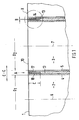
- 13 thermal expansion slots 14 are provided in the dividing walls running transversely to the longitudinal direction C-C. Milling, sawing or the like are introduced. It is sufficient if the thermal expansion slots 14 are approximately between 0.4 and 0.8 mm - dimension B - wide (FIG. 2) and approximately 20 mm deep - dimension C - (FIG. 1).
- the thermal expansion slots 14 open with their two ends 15, 16 into the cooling water channels 8, 9. So that the webs 17, 18 of each partition 3 are not damaged by cavitation during operation of the internal combustion engine, the thermal expansion slots 14 are sealed against water ingress from the cooling water channels 8, 9. This can be done by essentially filling the thermal expansion slots 14 with a cushion-like plastic 19 (FIG. 2), for example silicone.
- the plastic 19 can be introduced by casting or a similar method.
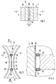
- sealing bodies 20, 21 are provided in the region of the ends 16, 17 of the thermal expansion slots 14, which are made of elastomer or plastic and prevent cooling water from entering the thermal expansion slots 14.
- the sealing bodies 20, 21 have a circular cylindrical basic shape and are fixed in corresponding bores 22, 23 which run parallel to the central axes 6, 7 of the cylinders 2, 3.
Description
Die Erfindung betrifft ein Zylinderkurbelgehäuse nach dem Oberbegriff des Patentanspruchs 1.The invention relates to a cylinder crankcase according to the preamble of patent claim 1.
Es ist bekannt (DE-PS 29 11 628), einzelne Leichtmetallzylinder, die luftgekühlt sind, im an den Zylinderkopf angrenzenden Bereich mit Wärmedehnungseinrichtungen zu versehen, die den dort auftretenden Verwerfungen und Ausbuchtungen entgegenwirken.It is known ( DE-PS 29 11 628 ) to provide individual light metal cylinders which are air-cooled in the area adjacent to the cylinder head with thermal expansion devices which counteract the distortions and bulges occurring there.
Die GB-A-2 010 394 behandelt ein Zylinderkurbelgehäuse für eine mehrzylindrige Brennkraftmaschine in dessen Zylinder eisenmetallische Zylinderlaufbüchsen vorgesehen sind. Die Zylinder sind durch quer zur Längsrichtung des Zylinderkurbelgehäuses verlaufende Trennwände getrennt und abschnittsweise von Kühlwasserkanälen umgeben. In den Trennwänden sind Schlitze vorgesehen, die von der Trennebene zwischen dem Zylinderkopf und dem Zylinderkurbelgehäuse aus eingebracht sind.GB-A-2 010 394 deals with a cylinder crankcase for a multi-cylinder internal combustion engine in the cylinder of which iron-metallic cylinder liners are provided. The cylinders are separated by partitions running transversely to the longitudinal direction of the cylinder crankcase and are partially surrounded by cooling water channels. Slots are provided in the partitions, which are introduced from the parting plane between the cylinder head and the cylinder crankcase.
Aufgabe der Erfindung ist es, an einem mehrere Zylinder umfassenden, mit Kühlwasserkanälen ausgestatteten Zylinderkurbelgehäuse aus einer Leichtmetalllegierung gezielte Wärmedehnungsmaßnahmen zu verwirklichen. Dabei sollte aber sichergestellt sein, daß trotz dieser Maßnahmen die Standfestigkeit des Zylinderkurbelgehäuses erhalten bleibt.The object of the invention is to implement targeted thermal expansion measures on a cylinder crankcase comprising a plurality of cylinders and equipped with cooling water channels and made of a light metal alloy. It should be ensured, however, that the stability of the cylinder crankcase is maintained despite these measures.
Erfindungsgemäß wird diese Aufgabe durch die kennzeichnenden Merkmale des Patentanspruchs 1 gelöst. Weitere, die Erfindung ausgestaltende Merkmale sind in den Unteransprüchen enthalten.According to the invention, this object is achieved by the characterizing features of patent claim 1. Further features embodying the invention are contained in the subclaims.
Die mit der Erfindung hauptsächlich erzielten Vorteile sind darin zu sehen, daß durch die Wärmedehnungsschlitze einerseits die im Betrieb der Brennkraftmaschine am Zylinderkurbelgehäuse - es besteht ja aus einer Leichtmetalllegierung - auftretenden Temperaturtoleranzen ausgeglichen werden und andererseits mechanischer Verschleiß, beispielsweise durch Eintritt von Kühlwasser in die Wärmedehnungsschlitze hervorgerufene Kavitation, aufgrund der elastischen Dichtmittel zwischen den Kühlkanälen und den Wärmedehnungsschlitzen entgegengewirkt ist. Dies kann auf einfache Weise durch die Dichtkörper oder den die Wärmedehnungsschlitze ausfüllenden polsterartigen Kunststoff erreicht werden.The main advantages achieved with the invention are that the thermal expansion slots compensate for the temperature tolerances occurring during operation of the internal combustion engine on the cylinder crankcase - it consists of a light metal alloy - and mechanical wear, for example caused by the entry of cooling water into the thermal expansion slots Cavitation, due to the elastic sealant between the cooling channels and the thermal expansion slots is counteracted. This can be achieved in a simple manner by means of the sealing body or the cushion-like plastic filling the thermal expansion slots.
In der Zeichnung werden Ausführungsbeispiele der Erfindung gezeigt, die nachstehend näher beschrieben sind.In the drawing, exemplary embodiments of the invention are shown, which are described in more detail below.
Es zeigt
- Fig. 1 eine Teilansicht eines Längsschnitts durch ein Brennkraftmaschinen-Zylinderkurbelgehäuse,
- Fig. 2 eine Einzelheit X der Fig. 1 in größerem Maßstab,
- Fig. 3 eine Ansicht in Pfeilrichtung A der Fig. 1,
- Fig. 4 einen Schnitt nach der Linie I -I der Fig. 3.
- 1 is a partial view of a longitudinal section through an internal combustion engine cylinder crankcase,
- 2 shows a detail X of FIG. 1 on a larger scale,
- 3 is a view in the direction of arrow A of FIG. 1,
- 4 shows a section along the line I -I of FIG. 3rd
Das Zylinderkurbelgehäuse 1 ist Bestandteil einer nicht näher dargestellten Hubkolben-Brennkraftmaschine mit mehreren Zylindern der Reihenbauart, die im Viertakt-Verfahren arbeitet. Aus Gewichtsgründen besteht das Zylinderkurbelgehäuse 1 aus einer Leichtmetalllegierung, wobei in die einzelnen beabstandeten Zylinder 2, 3 eisenmetallische Zylinderlaufbüchsen 4, 5 eingesetzt sind. Mit 6 und 7 sind die Mittelachsen der Zylinder 2, 3 bezeichnet. Außerdem sind die Zylinder 2, 3 über einen wesentlichen Teilbereich von Kühlwasserkanälen 8, 9 umgeben.The cylinder crankcase 1 is part of a reciprocating internal combustion engine, not shown, with a plurality of cylinders of the series type, which works in the four-stroke process. For reasons of weight, the cylinder crankcase 1 is made of a light metal alloy, iron-
Darüber hinaus wird das Zylinderkurbelgehäuse 1 von einer Trennebene 10 begrenzt, die sich zwischen besagtem Gehäuse und einem Zylinderkopf 11 erstreckt (Fig. 4). Eine Zylinderkopfdichtung ist mit 12 bezeichnet. Beiderseits der Trennebene 10 sind Wärme abgebende Brennraüme vorgesehen durch die aufrechte Trennwände 13 - sie trennen im Bereich der Zylinderkurbelgehaüses auch die Kühlwasserkanäle 8,9 - zwischen den Zylinder 2, 3 besonderen Temperaturbeanspruchungen unterliegen. Um sie - in Längsrichtung C-C Zylinderkurbelgehäuse gesehenauszugleichen, d.h. um die Durchmesser D₁ und D₂ der Zylinder 2, 3 im Rahmen festgelegter Toleranzen zu halten, sind in den quer zur Längsrichtung C-C verlaufenden Trennwänden 13 Wärmedehnungsschlitze 14 vorgesehen, die von der Trennebene 10 aus mittels mechanischer Verfahren, z.B. Fräsen, Sägen oder dergleichen, eingebracht sind. Dabei genügt es, wenn die Wärmedehnungsschlitze 14 etwa zwischen 0,4 und 0,8 mm - Maß B - breit (Fig. 2) und etwa 20 mm tief - Maß C - sind (Fig. 1).In addition, the cylinder crankcase 1 is delimited by a
Die Wärmedehnungsschlitze 14 münden mit ihren beiden Enden 15, 16 in die Kühlwasserkanäle 8, 9. Damit die Stege 17, 18 jeder Trennwand 3 nicht durch Kavitation während des Betriebs der Brennkraftmaschine beschädigt werden, sind die Wärmedehnungsschlitze 14 gegen Wassereintritt aus den Kühlwasserkanälen 8, 9 abgedichtet. Dies kann dadurch erfolgen, daß die Wärmedehnungsschlitze 14 mit einem polsterkörperartigen Kunststoff 19 (Fig. 2), beispielsweise Silikon, im wesentlichen ausgefüllt sind. Der Kunststoff 19 kann durch Gießen oder ein ähnliches Verfahren eingebracht werden.The
Gemäß Fig. 3 sind im Bereich der Enden 16, 17 der Wärmedehnungsschlitze 14 Dichtkörper 20, 21 vorgesehen, die aus Elastomer oder Kunststoff bestehen und Kühlwassereintritt in die Wärmedehnungsschlitze 14 verhindern. Die Dichtkörper 20, 21 weisen eine kreiszylindrische Grundform auf und sind in korrespondierenden Bohrungen 22, 23 festgesetzt, die parallel zu den Mittelachsen 6, 7 der Zylinder 2, 3 verlaufen.According to FIG. 3,
Claims (5)
Applications Claiming Priority (2)
| Application Number | Priority Date | Filing Date | Title |
|---|---|---|---|
| DE3907099A DE3907099C1 (en) | 1989-03-04 | 1989-03-04 | |
| DE3907099 | 1989-03-04 |
Publications (2)
| Publication Number | Publication Date |
|---|---|
| EP0386329A1 EP0386329A1 (en) | 1990-09-12 |
| EP0386329B1 true EP0386329B1 (en) | 1992-03-11 |
Family
ID=6375610
Family Applications (1)
| Application Number | Title | Priority Date | Filing Date |
|---|---|---|---|
| EP89122254A Expired - Lifetime EP0386329B1 (en) | 1989-03-04 | 1989-12-02 | Cylinder block |
Country Status (5)
| Country | Link |
|---|---|
| US (1) | US4974569A (en) |
| EP (1) | EP0386329B1 (en) |
| JP (1) | JPH02271057A (en) |
| DE (2) | DE3907099C1 (en) |
| ES (1) | ES2030256T3 (en) |
Families Citing this family (11)
| Publication number | Priority date | Publication date | Assignee | Title |
|---|---|---|---|---|
| CN100363703C (en) * | 2001-10-24 | 2008-01-23 | 贝洱两合公司 | Thermal conductor |
| DE10218521A1 (en) * | 2002-04-25 | 2003-11-06 | Behr Gmbh & Co | Exhaust gas heat exchanger, especially for motor vehicles |
| US20050150476A1 (en) * | 2002-08-06 | 2005-07-14 | Uwe Gohrbandt | Combination of cylinder liners consisting of a light metal alloy |
| US7098173B2 (en) * | 2002-11-19 | 2006-08-29 | General Motors Corporation | Thermally stable antifoam agent for use in automatic transmission fluids |
| US20040121921A1 (en) * | 2002-12-20 | 2004-06-24 | Calcut Brent D. | Thermally stable antifoam agent and methods for use in functional fluids |
| US7056870B2 (en) * | 2003-02-12 | 2006-06-06 | General Motors Corporation | Controlled release of antifoam additives from compounded rubber |
| US7087674B2 (en) * | 2003-02-12 | 2006-08-08 | General Motors Corporation | Controlled release of perfluoropolyether antifoam additives from compounded rubber |
| FR2887926B1 (en) * | 2005-06-29 | 2010-08-13 | Peugeot Citroen Automobiles Sa | CYLINDER SHAPER FOR AN INTERNAL COMBUSTION ENGINE AND BLOCK CYLINDERS EQUIPPED WITH SUCH A SHIRT |
| JP4913135B2 (en) * | 2005-07-06 | 2012-04-11 | チーム オリオン ヨーロッパ エス.エー. | 2-stroke engine especially for land craft, water craft or air craft models |
| US7677218B2 (en) * | 2007-07-31 | 2010-03-16 | Caterpillar Inc. | Cylinder head including a stress slot with filler |
| EP2309114B1 (en) * | 2009-07-30 | 2012-09-12 | Ford Global Technologies, LLC | Cooling system |
Family Cites Families (8)
| Publication number | Priority date | Publication date | Assignee | Title |
|---|---|---|---|---|
| DE2756120A1 (en) * | 1977-12-16 | 1979-06-21 | Daimler Benz Ag | CYLINDER BLOCK FOR A PARTICULAR AIR COMPRESSING COMBUSTION MACHINE |
| DE2836810A1 (en) * | 1978-08-23 | 1980-03-06 | Daimler Benz Ag | CYLINDER BLOCK EXISTING FROM LIGHT METAL DIE CASTING |
| DE2911628C2 (en) * | 1979-03-24 | 1982-09-09 | Mahle Gmbh, 7000 Stuttgart | Light metal cylinders for internal combustion engines |
| JPS5985446A (en) * | 1982-11-04 | 1984-05-17 | Fuji Heavy Ind Ltd | Cylinder block of internal-combustion engine with multicylinder |
| DE3408490A1 (en) * | 1984-03-08 | 1985-09-12 | Willibald 8000 München Hiemer | Cylinder block of a water-cooled reciprocating piston internal combustion engine |
| JPS62225751A (en) * | 1986-03-27 | 1987-10-03 | Daihatsu Motor Co Ltd | Cooling device for siamese type cylinder block |
| DE3623742A1 (en) * | 1986-07-14 | 1988-01-28 | Opel Adam Ag | Cylinder block for an internal combustion engine |
| US4856462A (en) * | 1986-11-13 | 1989-08-15 | Honda Giken Kogyo Kabushiki Kaisha | Cylinder block made of fiber-reinforced light alloy for internal combustion engine |
-
1989
- 1989-03-04 DE DE3907099A patent/DE3907099C1/de not_active Expired
- 1989-12-02 DE DE8989122254T patent/DE58900959D1/en not_active Expired - Lifetime
- 1989-12-02 ES ES198989122254T patent/ES2030256T3/en not_active Expired - Lifetime
- 1989-12-02 EP EP89122254A patent/EP0386329B1/en not_active Expired - Lifetime
-
1990
- 1990-02-20 US US07/481,314 patent/US4974569A/en not_active Expired - Fee Related
- 1990-03-02 JP JP2049674A patent/JPH02271057A/en active Pending
Also Published As
| Publication number | Publication date |
|---|---|
| ES2030256T3 (en) | 1992-10-16 |
| DE3907099C1 (en) | 1989-11-16 |
| US4974569A (en) | 1990-12-04 |
| DE58900959D1 (en) | 1992-04-16 |
| EP0386329A1 (en) | 1990-09-12 |
| JPH02271057A (en) | 1990-11-06 |
Similar Documents
| Publication | Publication Date | Title |
|---|---|---|
| EP0386329B1 (en) | Cylinder block | |
| DE3543747C2 (en) | ||
| DE3544215A1 (en) | CYLINDER BLOCK STRUCTURE FOR A MULTI-CYLINDER INTERNAL COMBUSTION ENGINE | |
| EP0882901A2 (en) | Method of manufacturing a bearing assembly and bearing assembly manufactured according to it | |
| DE2638025B2 (en) | Water-cooled internal combustion engine | |
| EP0842356B1 (en) | Engine block for a multi-cylinder internal combustion engine | |
| EP1834075B1 (en) | Cooling jacket for a cylinder head | |
| EP1013948A2 (en) | Crankshaft bearing for a combustion engine | |
| DE10339244A1 (en) | cylinder head | |
| DE3300924C2 (en) | ||
| DE4324609C2 (en) | Crankcase for internal combustion engines | |
| DE1936022A1 (en) | Liquid-cooled reciprocating internal combustion engine | |
| DE102019112918B3 (en) | Core for use in the casting of a crankcase | |
| DE4206165C2 (en) | Crankcase for a reciprocating piston internal combustion engine | |
| DE2727056A1 (en) | DEVICE FOR CAST ENGINE BLOCKS FOR WATER-COOLED TWO-STROKE ENGINES | |
| EP0486463B2 (en) | Casting mold for cylinder block of a V-type internal combustion engine | |
| DE3121408C2 (en) | Liquid-cooled multi-cylinder internal combustion engine | |
| DE10350500B4 (en) | Method for enlarging engine cylinder bores | |
| AT519596B1 (en) | PROCESS FOR MANUFACTURING A CAST, LIQUID-COOLED CYLINDER CRANKCASE | |
| DE10009776C1 (en) | Cylinder head for an IC motor has a slit at the surface towards the crankcase opposite the cylinder dividing web to form part of the coolant circuit | |
| DE102017216694A1 (en) | Internal combustion engine housing with cylinder cooling | |
| EP1674704A2 (en) | Crankshaft bearing beam for an internal combustion engine | |
| DE3542137C2 (en) | ||
| EP1311752B1 (en) | Crankcase for an internal combustion engine, especially for a boxer engine | |
| EP0782667B1 (en) | Combustion air duct of an internal combustion engine |
Legal Events
| Date | Code | Title | Description |
|---|---|---|---|
| PUAI | Public reference made under article 153(3) epc to a published international application that has entered the european phase |
Free format text: ORIGINAL CODE: 0009012 |
|
| AK | Designated contracting states |
Kind code of ref document: A1 Designated state(s): DE ES FR GB IT |
|
| 17P | Request for examination filed |
Effective date: 19901221 |
|
| 17Q | First examination report despatched |
Effective date: 19910325 |
|
| ITF | It: translation for a ep patent filed |
Owner name: DE DOMINICIS & MAYER S.R.L. |
|
| GRAA | (expected) grant |
Free format text: ORIGINAL CODE: 0009210 |
|
| AK | Designated contracting states |
Kind code of ref document: B1 Designated state(s): DE ES FR GB IT |
|
| REF | Corresponds to: |
Ref document number: 58900959 Country of ref document: DE Date of ref document: 19920416 |
|
| GBT | Gb: translation of ep patent filed (gb section 77(6)(a)/1977) | ||
| ET | Fr: translation filed | ||
| REG | Reference to a national code |
Ref country code: ES Ref legal event code: FG2A Ref document number: 2030256 Country of ref document: ES Kind code of ref document: T3 |
|
| PGFP | Annual fee paid to national office [announced via postgrant information from national office to epo] |
Ref country code: ES Payment date: 19921215 Year of fee payment: 4 |
|
| PLBE | No opposition filed within time limit |
Free format text: ORIGINAL CODE: 0009261 |
|
| STAA | Information on the status of an ep patent application or granted ep patent |
Free format text: STATUS: NO OPPOSITION FILED WITHIN TIME LIMIT |
|
| 26N | No opposition filed | ||
| PG25 | Lapsed in a contracting state [announced via postgrant information from national office to epo] |
Ref country code: ES Free format text: LAPSE BECAUSE OF EXPIRATION OF PROTECTION Effective date: 19931203 |
|
| PGFP | Annual fee paid to national office [announced via postgrant information from national office to epo] |
Ref country code: GB Payment date: 19991201 Year of fee payment: 11 |
|
| PGFP | Annual fee paid to national office [announced via postgrant information from national office to epo] |
Ref country code: FR Payment date: 19991230 Year of fee payment: 11 |
|
| PG25 | Lapsed in a contracting state [announced via postgrant information from national office to epo] |
Ref country code: GB Free format text: LAPSE BECAUSE OF NON-PAYMENT OF DUE FEES Effective date: 20001202 |
|
| PGFP | Annual fee paid to national office [announced via postgrant information from national office to epo] |
Ref country code: DE Payment date: 20001214 Year of fee payment: 12 |
|
| REG | Reference to a national code |
Ref country code: ES Ref legal event code: FD2A Effective date: 20010301 |
|
| GBPC | Gb: european patent ceased through non-payment of renewal fee |
Effective date: 20001202 |
|
| PG25 | Lapsed in a contracting state [announced via postgrant information from national office to epo] |
Ref country code: FR Free format text: LAPSE BECAUSE OF NON-PAYMENT OF DUE FEES Effective date: 20010831 |
|
| REG | Reference to a national code |
Ref country code: FR Ref legal event code: ST |
|
| PG25 | Lapsed in a contracting state [announced via postgrant information from national office to epo] |
Ref country code: DE Free format text: LAPSE BECAUSE OF NON-PAYMENT OF DUE FEES Effective date: 20020702 |
|
| PG25 | Lapsed in a contracting state [announced via postgrant information from national office to epo] |
Ref country code: IT Free format text: LAPSE BECAUSE OF NON-PAYMENT OF DUE FEES;WARNING: LAPSES OF ITALIAN PATENTS WITH EFFECTIVE DATE BEFORE 2007 MAY HAVE OCCURRED AT ANY TIME BEFORE 2007. THE CORRECT EFFECTIVE DATE MAY BE DIFFERENT FROM THE ONE RECORDED. Effective date: 20051202 |