EP0386306A2 - Circuit for avoiding step forming in tape winding of a recording and/or reproducing apparatus - Google Patents
Circuit for avoiding step forming in tape winding of a recording and/or reproducing apparatus Download PDFInfo
- Publication number
- EP0386306A2 EP0386306A2 EP89110346A EP89110346A EP0386306A2 EP 0386306 A2 EP0386306 A2 EP 0386306A2 EP 89110346 A EP89110346 A EP 89110346A EP 89110346 A EP89110346 A EP 89110346A EP 0386306 A2 EP0386306 A2 EP 0386306A2
- Authority
- EP
- European Patent Office
- Prior art keywords
- tape
- recording
- motor
- rewound
- circuit arrangement
- Prior art date
- Legal status (The legal status is an assumption and is not a legal conclusion. Google has not performed a legal analysis and makes no representation as to the accuracy of the status listed.)
- Granted
Links
Images

Classifications
-
- G—PHYSICS
- G11—INFORMATION STORAGE
- G11B—INFORMATION STORAGE BASED ON RELATIVE MOVEMENT BETWEEN RECORD CARRIER AND TRANSDUCER
- G11B15/00—Driving, starting or stopping record carriers of filamentary or web form; Driving both such record carriers and heads; Guiding such record carriers or containers therefor; Control thereof; Control of operating function
- G11B15/60—Guiding record carrier
- G11B15/66—Threading; Loading; Automatic self-loading
-
- G—PHYSICS
- G11—INFORMATION STORAGE
- G11B—INFORMATION STORAGE BASED ON RELATIVE MOVEMENT BETWEEN RECORD CARRIER AND TRANSDUCER
- G11B15/00—Driving, starting or stopping record carriers of filamentary or web form; Driving both such record carriers and heads; Guiding such record carriers or containers therefor; Control thereof; Control of operating function
- G11B15/02—Control of operating function, e.g. switching from recording to reproducing
- G11B15/03—Control of operating function, e.g. switching from recording to reproducing by using counters
-
- G—PHYSICS
- G11—INFORMATION STORAGE
- G11B—INFORMATION STORAGE BASED ON RELATIVE MOVEMENT BETWEEN RECORD CARRIER AND TRANSDUCER
- G11B15/00—Driving, starting or stopping record carriers of filamentary or web form; Driving both such record carriers and heads; Guiding such record carriers or containers therefor; Control thereof; Control of operating function
- G11B15/18—Driving; Starting; Stopping; Arrangements for control or regulation thereof
- G11B15/26—Driving record carriers by members acting directly or indirectly thereon
- G11B15/32—Driving record carriers by members acting directly or indirectly thereon through the reels or cores on to which the record carrier is wound
Definitions
- the invention relates to a circuit arrangement for avoiding excessive step formation in the tape winding of a recording and / or reproducing device according to the preamble of claims 1, 2, 3 and 4.
- Answering machines of this type are generally known. However, they have one major disadvantage. During recurring sequences of the announcement, the tape is first moved in the starting direction and then brought back to its starting position by a return. Since this process is repeated very often, steps can occur in the tape wraps in the cassette, with the result, for example, of inadequacies in the tape guide, with the result that the cassette becomes stiff and in extreme cases the tape is damaged.
- the subject of patent application P 37 43 838 provides a counting device which counts the number of announcement cycles.
- the device for controlling the tape transport receives a control signal from the counting device, which first triggers the forwarding and then the returning of the tape, in order only to wind the announcement tape first in the forward and then in the reverse direction.
- an erase circuit is provided which resets the counting device to zero for a new count cycle as soon as the tape has returned to its starting position for an announcement after rewinding.
- the present invention is based on the object, starting from patent application P 37 43 838, to further develop a circuit arrangement such that an excessive step formation of the tape winding can be avoided for any recording and / or reproducing device.
- the circuit arrangement according to claim 1 can be used with any recording and / or playback device, for example answering machine with two magnetic tape memories designed as a cassette or telephone / car telephone with answering machine or information system or dictation machine or magnetic tape device for entertainment electronics, etc.
- any recording and / or playback device for example answering machine with two magnetic tape memories designed as a cassette or telephone / car telephone with answering machine or information system or dictation machine or magnetic tape device for entertainment electronics, etc.
- the entire tape is rewound once in the forward direction and once in the reverse direction, as a result of which any steps in the tape winding that have arisen are eliminated.
- the rewinding process can also, according to patent claim 2, by a motor current indicator and a threshold switch connected to it, or, according to patent claim 3, by a control voltage that can be tapped from a control device of the motor or, according to patent claim 4, by evaluating signals at the output of those used for belt positioning Pulse generators are triggered in a microprocessor. These criteria are a measure of the actual stiffness, while only an empirically determined rule of thumb is used as a triggering criterion in the circuit arrangement according to claim 1.
- the stiffness of the tape winding can be measured in a simple manner with a motor current indicator; however, the circuitry required for this is relatively large.
- the circuitry is less, but the dimensioning must take into account the scatter of the motor constants.
- the circuit complexity can be further reduced if a microprocessor, which is arranged in the recording and / or playback device anyway, can be used, as is the case, for example, for determining the elapsed playing time or tape length and / or remaining time of cassettes or reels of tape-shaped information carriers from DE-PS 26 50 665 is known.
- a counting device Counts the number of calls received without message recording, so the winding and rewinding of the tape reel of the recording cassette can be carried out regardless of the number of announcement cycles.
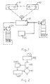
- a counting device Z1 which counts the number of announcement cycles.
- a device ST for controlling the tape transport receives - when a predetermined number of announcement cycles has been reached - a control signal from the counting device Z1, which first triggers the forwarding and then the returning of the tape of the announcement cassette A1, around the tape first in forward and then in reverse direction. The tape is then rewound to its starting position for an announcement.
- the winding through and rewinding of the tape reel of the recording cassette A2 can also be carried out afterwards (or before). Details of the drive, e.g. the control device RE are not shown in FIG. 1.
- the number of announcement cycles, after which both tapes are forwarded and rewound one after the other, is determined empirically and can be 33 for a stenocassette, for example.
- the number of announcement cycles until the tape of the recording and announcement cassette A2 and A1 can be spooled through can also be selected by the user, as will be the case, for example, with a microcassette.
- a second counting device Z2 in the form of an up-counter with an internal reset input (indicated by the dashed line) can also be provided, which is connected to the device ST.
- the two drives for the announcement cassette A1 and the recording cassette A2 are driven by the same motor M (indicated by the chain line in the figure).
- a speech recognition circuit SE (which can be connected to the telecommunication line) is connected to the device ST and the second counting device Z2, with which speech pauses of, for example, more than 8 seconds can be recognized.
- the speech recognition circuit SE can reliably detect when, for example, the caller has hung up and the answering machine is switched off by means of a microprocessor MP and / or device ST arranged in the answering machine and the drive for the recording cassette A2 is stopped. If such a microprocessor MP is present, then this can Take over the function of the two counting devices Z1 and Z2, which can then be omitted.
- a device for automatic pause reduction arranged in the answering machine ensures that there are no pauses of, for example, more than two seconds between the messages of the individual callers.
- the announcement text is usually divided into a message, a message asking the caller to speak and a final announcement.
- the drive of the recording cassette A2 is then driven by the motor M. If the caller hangs up after the final announcement, this is recognized at the latest after 8 seconds by means of speech recognition circuit SE, the tape of the recording cassette A2 is rewound into its starting position and the count of the counting device Z2 is increased by one. In the event that the predetermined number of incoming calls without message recording of, for example, five is exceeded, the tape of the recording cassette A2 is first spooled in the forward and then in the reverse direction (or vice versa) and then rewound into the starting position.
- the starting position can be derived, for example, from the rotational speed of the drive of the recording cassette A2. Furthermore, it is also possible to store the starting position in a digital memory and using a microprocessor MP and / or up / down counter to move back to this starting position, the counting pulses being obtained by scanning one of the windings.
- the counting devices Z1 and Z2 are replaced by a motor current indicator MI, which detects the increasing stiffness of the tape winding or a cassette via the higher motor current. When a predetermined threshold value is exceeded, the cassettes are rewound and rewound into the starting position.
- the motor current indicator MI is connected both to a control device RE and to a threshold switch SWI, which is connected to a microprocessor MP.
- a threshold value circuit SWS is connected to the control device RE and to the motor M and is connected to the microprocessor MP.
- the control voltage that can be tapped at the control device RE triggers the rewinding process of the tapes and the tape is rewound back into the original starting position by means of a microprocessor MP.
- the back EMF of the motor M or the tacho voltage can serve as a threshold.
- the signals at the output of pulse generators used for band positioning can also be evaluated in a microprocessor MP. This determines the respective belt position and the associated target belt speed. When a permissible deviation from the desired tape speed is exceeded, the entire tape for two tapes is rewound simultaneously or successively first in the forward and then in the reverse direction, and after the rewinding process, the tape is rewound back into the original starting position.
Landscapes
- Indexing, Searching, Synchronizing, And The Amount Of Synchronization Travel Of Record Carriers (AREA)
- Television Signal Processing For Recording (AREA)
- Signal Processing For Digital Recording And Reproducing (AREA)
- Digital Magnetic Recording (AREA)
- Control Of Stepping Motors (AREA)
Abstract
Description
Die Erfindung betrifft eine Schaltungsanordnung zur Vermeidung von zu großer Stufenbildung im Bandwickel eines Aufnahme- und/oder Wiedergabegeräts gemäß dem Oberbegriff der Patentansprüche 1, 2, 3 und 4.The invention relates to a circuit arrangement for avoiding excessive step formation in the tape winding of a recording and / or reproducing device according to the preamble of
Aus der nichtvorveröffentlichten deutschen Patentanmeldung P 37 43 838 ist ein Anrufbeantworter mit einem als Cassette ausgebildeten Bandspeicher für einen Ansagetext sowie mit einer Einrichtung zur Steuerung des Bandtransports und einem Ansagelaufwerk, welches das Band nach jeder Ansage in seine Ausgangsposition zurückspult, bekannt.From the unpublished German patent application P 37 43 838 an answering machine is known with a tape memory designed as a cassette for an announcement text and with a device for controlling the tape transport and an announcement drive which rewinds the tape into its starting position after each announcement.
Anrufbeantworter dieser Art sind grundsätzlich bekannt. Sie haben jedoch einen entscheidenden Nachteil. Während immer wiederkehrender Abläufe des Ansagetextes wird das Band zunächst in Startrichtung bewegt und anschließend durch einen Rücklauf wieder in seine Ausgangsposition gebracht. Da sich dieser Vorgang sehr oft wiederholt, kann - z.B. unterstützt durch Unzulänglichkeiten in der Bandführung - bei den Bandwickeln in der Cassette eine Stufenbildung entstehen, mit der Folge, daß die Cassette schwergängig und im Grenzfall das Band beschädigt wird.Answering machines of this type are generally known. However, they have one major disadvantage. During recurring sequences of the announcement, the tape is first moved in the starting direction and then brought back to its starting position by a return. Since this process is repeated very often, steps can occur in the tape wraps in the cassette, with the result, for example, of inadequacies in the tape guide, with the result that the cassette becomes stiff and in extreme cases the tape is damaged.
Zur Vermeidung einer zu starken Stufenbildung der Bandwickel, die eine Beeinträchtigung der Bandbewegung oder eine Beschädigung des Bandes zur Folge haben könnte, ist beim Gegenstand der Patentanmeldung P 37 43 838 eine Zähleinrichtung vorgesehen, die die Anzahl der Ansagezyklen zählt. Die Einrichtung zur Steuerung des Bandtransports erhält - beim Erreichen einer vorgegebenen Anzahl von Ansagezyklen - von der Zähleinrichtung ein Steuersignal, das zunächst den Vorlauf und anschließend den Rücklauf des Bandes auslöst, um nur das Ansageband zuerst in Vorwärts- und dann in Rückwärtsrichtung durchzuspulen. Schließlich ist eine Löschschaltung vorgesehen, die die Zähleinrichtung für einen neuen Zählzyklus auf Null zurücksetzt, sobald das Band nach dem Umspulen wieder seine Ausgangsposition für eine Ansage eingenommen hat. Eine Anregung, in welcher Weise eine zu große Stufenbildung bei einer Aufzeichnungscassette vermeiden werden kann, ist der Patentanmeldung P 37 43 838 nicht entnehmbar.To avoid excessive step formation of the tape roll, which could impair the tape movement or damage the tape, the subject of patent application P 37 43 838 provides a counting device which counts the number of announcement cycles. When a predetermined number of announcement cycles has been reached, the device for controlling the tape transport receives a control signal from the counting device, which first triggers the forwarding and then the returning of the tape, in order only to wind the announcement tape first in the forward and then in the reverse direction. Finally, an erase circuit is provided which resets the counting device to zero for a new count cycle as soon as the tape has returned to its starting position for an announcement after rewinding. A suggestion as to how excessive step formation can be avoided in a recording cassette cannot be found in patent application P 37 43 838.
Der vorliegenden Erfindung liegt die Aufgabe zugrunde, ausgehend von der Patentanmeldung P 37 43 838 eine Schaltungsanordnung so weiterzubilden, daß für ein beliebiges Aufnahme- und/oder Wiedergabegerät eine zu große Stufenbildung des Bandwickels vermieden werden kann.The present invention is based on the object, starting from patent application P 37 43 838, to further develop a circuit arrangement such that an excessive step formation of the tape winding can be avoided for any recording and / or reproducing device.
Diese Aufgabe wird bei einer gattungsgemäßen Schaltungsanordnung durch die kennzeichnenden Merkmale der Patentansprüche 1 oder 2 oder 3 oder 4 gelöst.This object is achieved in a generic circuit arrangement by the characterizing features of
Die Schaltungsanordnung nach Patentanspruch 1 kann bei einem beliebigen Aufnahme- und/oder Wiedergabegerät eingesetzt werden, z.B. Anrufbeantworter mit zwei als Cassette ausgebildeten Magnetbandspeichern oder Fernsprechapparat/Autotelefon mit Anrufbeantworter oder Auskunftssystem oder Diktiergerät oder Magnetbandgerät der Unterhaltungselektronik usw.. Dabei wird - in Abhängigkeit von der Anzahl von unmittelbar aufeinanderfolgenden und an die ursprüngliche Bandposition zurückkehrenden Bewegungsabläufen - zu einem
geeigneten Zeitpunkt das gesamte Band, einmal in Vorwärtsrichtung und einmal in Rückwärtsrichtung umgespult, wodurch eventuell entstandene Stufen im Bandwickel beseitigt werden.The circuit arrangement according to
at a suitable point in time, the entire tape is rewound once in the forward direction and once in the reverse direction, as a result of which any steps in the tape winding that have arisen are eliminated.
Der Umspulvorgang kann auch, gemäß Patentanspruch 2, durch einen Motorstromindikator und einen mit diesem verbundenen Schwellwertschalter oder, gemäß Patentanspruch 3, durch eine an einer Regeleinrichtung des Motors abgreifbare Regelspannung oder, gemäß Patentanspruch 4, durch Auswertung von Signalen am Ausgang von zur Bandpositionierung dienenden Impulsgebern in einem Mikroprozessor ausgelöst werden. Diese Kriterien sind ein Maß für die tatsächliche Schwergängigkeit, während bei der Schaltungsanordnung nach Patentanspruch 1 nur eine empirisch ermittelte Faustregel als Auslösekriterium benutzt wird. Mit einem Motorstromindikator kann die Schwergängigkeit des Bandwickels auf einfache Art und Weise gemessen werden; der Schaltungsaufwand hierfür ist jedoch relativ groß. Bei einer Auslösung des Umspulvorgangs in Abhängigkeit von der Regelspannung ist zwar der Schaltungsaufwand geringer, jedoch muß bei der Dimensionierung die Streuung der Motorkonstanten mitberücksichtigt werden. Der Schaltungsaufwand kann weiter reduziert werden, wenn ein ohnehin im Aufnahme- und/oder Wiedergabegerät angeordneter Mikroprozessor mitbenutzt werden kann, wie dies beispielsweise für die Ermittlung der abgelaufenen Spielzeit bzw. Bandlänge und/oder Restlaufzeit von Cassetten oder Spulen bandförmiger Informationsträger aus der DE-PS 26 50 665 bekannt ist.The rewinding process can also, according to patent claim 2, by a motor current indicator and a threshold switch connected to it, or, according to patent claim 3, by a control voltage that can be tapped from a control device of the motor or, according to patent claim 4, by evaluating signals at the output of those used for belt positioning Pulse generators are triggered in a microprocessor. These criteria are a measure of the actual stiffness, while only an empirically determined rule of thumb is used as a triggering criterion in the circuit arrangement according to
Die Auswertung der Gegen-EMK des Motors oder der Tachospannung, gemäß Patentanspruch 5, ist für die Steuerung des Bandtransports an sich aus der DE-OS 22 59 497 bekannt.The evaluation of the back emf of the motor or the tachometer voltage, according to
Ist gemäß der im Patentanspruch 7 angegebenen Ausführungsform eine Zähleinrichtung vorgesehen, die die Anzahl der eingegenen Anrufe ohne Nachrichtenaufzeichnung zählt, so kann das Durchspulen und Umspulen des Bandwickels der Aufzeichnungscassette unabhängig von der Anzahl der Ansagezyklen vorgenommen werden.Is provided according to the embodiment specified in claim 7, a counting device Counts the number of calls received without message recording, so the winding and rewinding of the tape reel of the recording cassette can be carried out regardless of the number of announcement cycles.
Bei der im Patentanspruch 8 angegebenen Ausführungsform können für die Zähleinrichtung handelsübliche, kostengünstige Vorwärtszähler eingesetzt werden.
- Fig. 1 eine erste Ausführungsform mit Zähleinrichtung zur Zählung von unmittelbar aufeinanderfolgenden und an die ursprüngliche Bandposition zurückkehrenden Bandbewegungsabläufen,
- Fig. 2 eine zweite Ausführungsform mit einem Motorstromindikator und einem mit diesem verbundenen Schwellwertschalter und
- Fig. 3 eine dritte Ausführungsform mit Messung der an einer Regeleinrichtung des Motors abgreifbaren Regelspannung.
- 1 shows a first embodiment with a counting device for counting immediately consecutive and returning to the original belt position belt movement sequences,
- Fig. 2 shows a second embodiment with a motor current indicator and a threshold switch connected to it and
- 3 shows a third embodiment with measurement of the control voltage which can be tapped at a control device of the motor.
Auch wenn im folgenden die Erfindung anhand der Benutzung bei einem Anrufbeantworter beschrieben ist, so ist der Einsatz bei allen Geräten möglich, welche einen Magnetbandspeicher aufweisen und bei denen eine Stufenbildung des Bandwickels zuverlässig vermieden werden soll (z. B. Streamer, Videorecorder). Gleiches gilt für Anrufbeantworter, welche einen digitalen Speicher für den Ansagetext und einen Bandspeicher für die Nachrichten der Anrufer aufweisen.Even if the invention is described below on the basis of use with an answering machine, use is possible with all devices which have a magnetic tape memory and in which one Stepping of the tape winding should be reliably avoided (e.g. streamer, video recorder). The same applies to answering machines which have a digital memory for the announcement text and a tape memory for the messages of the callers.
Gemäß der in Fig. 1 dargestellten ersten Ausführungsform der vorliegenden Erfindung ist eine Zähleinrichtung Z1 vorgesehen, die die Anzahl der Ansagezyklen zählt. Eine Einrichtung ST zur Steuerung des Bandtransportes (bzw. ein Mikroprozessor MP) erhält - beim Erreichen einer vorgegebenen Anzahl von Ansagezyklen - von der Zähleinrichtung Z1 ein Steuersignal, das zunächst den Vorlauf und anschließend den Rücklauf des Bandes der Ansagecassette A1 auslöst, um das Band zuerst in Vorwärts- und dann in Rückwärtsrichtung durchzuspulen. Danach wird das Band wieder in seine Ausgangsposition für eine Ansage umgespult. Im Vergleich zum Gegenstand der deutschen Patentanmeldung P 37 43 838 kann zusätzlich danach (oder zuvor) das Durchspulen und Umspulen des Bandwickels der Aufzeichnungscassette A2 vorgenommen werden. Einzelheiten des Laufwerkes, z.B. die Regeleinrichtung RE, sind in Fig. 1 nicht dargestellt.According to the first embodiment of the present invention shown in FIG. 1, a counting device Z1 is provided which counts the number of announcement cycles. A device ST for controlling the tape transport (or a microprocessor MP) receives - when a predetermined number of announcement cycles has been reached - a control signal from the counting device Z1, which first triggers the forwarding and then the returning of the tape of the announcement cassette A1, around the tape first in forward and then in reverse direction. The tape is then rewound to its starting position for an announcement. In comparison to the subject of German patent application P 37 43 838, the winding through and rewinding of the tape reel of the recording cassette A2 can also be carried out afterwards (or before). Details of the drive, e.g. the control device RE are not shown in FIG. 1.
Die Anzahl der Ansagezyklen, nach denen beide Bänder nacheinander einmal vor- und zurückgespult werden, wird empirisch ermittelt und kann zum Beispiel für eine Stenocassette bei 33 liegen. Die Anzahl der Ansagezyklen bis zum Durchspulen des Bandes der Aufzeichnungs- und Ansagecassette A2 und A1 kann vom Benutzer aber auch kleiner gewählt werden, wie dies beispielsweise bei einer Microcassette der Fall sein wird.The number of announcement cycles, after which both tapes are forwarded and rewound one after the other, is determined empirically and can be 33 for a stenocassette, for example. The number of announcement cycles until the tape of the recording and announcement cassette A2 and A1 can be spooled through can also be selected by the user, as will be the case, for example, with a microcassette.
Neben der ersten kann weiterhin eine zweite Zähleinrichtung Z2 in Form eines Vorwärtszählers mit internem Rücksetzeingang (durch die gestrichelte Linie angedeutet) vorgesehen sein, welche mit der Einrichtung ST verbunden ist. Die beiden Laufwerke für die Ansagecassette A1 und die Aufzeichnungscassette A2 werden von demselben Motor M angetrieben (in der Figur durch die strichpunktierte Linie angedeutet). Mit der Einrichtung ST und der zweiten Zähleinrichtung Z2 ist eine Spracherkennungsschaltung SE (welche an die Fernmeldeleitung anschaltbar ist) verbunden, mit der Sprechpausen von z.B. mehr als 8 Sekunden erkannt werden können. Mit der Spracherkennungsschaltung SE kann zuverlässig detektiert werden, wann z.B. der Anrufer aufgelegt hat und mittels im Anrufbeantworter angeordneten Mikroprozessor MP und/oder Einrichtung ST wird der Anrufbeantworter abgeschaltet und das Laufwerk für die Aufzeichnungscassette A2 stillgesetzt. Ist ein solcher Mikroprozessor MP vorhanden, so kann dieser die Funktion der beiden Zähleinrichtungen Z1 und Z2 übernehmen, welche dann entfallen können. Eine im Anrufbeantworter angeordnete Einrichtung zur automatischen Pausenreduzierung sorgt dafür, daß zwischen den Nachrichten der einzelnen Anrufer keine Pausen von z.B. mehr als zwei Sekunden entstehen.In addition to the first one, a second counting device Z2 in the form of an up-counter with an internal reset input (indicated by the dashed line) can also be provided, which is connected to the device ST. The two drives for the announcement cassette A1 and the recording cassette A2 are driven by the same motor M (indicated by the chain line in the figure). A speech recognition circuit SE (which can be connected to the telecommunication line) is connected to the device ST and the second counting device Z2, with which speech pauses of, for example, more than 8 seconds can be recognized. The speech recognition circuit SE can reliably detect when, for example, the caller has hung up and the answering machine is switched off by means of a microprocessor MP and / or device ST arranged in the answering machine and the drive for the recording cassette A2 is stopped. If such a microprocessor MP is present, then this can Take over the function of the two counting devices Z1 and Z2, which can then be omitted. A device for automatic pause reduction arranged in the answering machine ensures that there are no pauses of, for example, more than two seconds between the messages of the individual callers.
Der Ansagetext ist in der Regel in Meldung, Mitteilung mit Sprechaufforderung an den Anrufer und Schlußansage gegliedert. Nach der Schlußansage wird dann das Laufwerk der Aufzeichnungscassette A2 vom Motor M angetrieben. Legt der Anrufer nach der Schlußansage auf, so wird dies spätestens nach 8 sec. mittels Spracherkennungsschaltung SE erkannt, das Band der Aufzeichnungscassette A2 wieder in seine Ausgangsposition zurückgespult und der Zählerstand der Zähleinrichtung Z2 um eins erhöht. Für den Fall, daß die vorgegebene Anzahl eingegangener Anrufe ohne Nachrichtenaufzeichnung von z.B. fünf überschritten wird, wird das Band der Aufzeichnungscassette A2 zuerst in Vorwärts- und dann in Rückwärtsrichtung (oder umgekehrt) durchgespult und anschließend wieder in die Ausgangsposition umgespult. Die Ausgangsposition kann beispielsweise aus der Umdrehungsgeschwindigkeit des Laufwerks der Aufzeichnungscassette A2 abgeleitet werden. Weiterhin ist es auch möglich, die Ausgangsposition in einem digitalen Speicher abzulegen und mittels Mikroprozessor MP und/oder Vorwärts-/Rückwärtszähler diese Ausgangsposition wieder anzufahren, wobei die Zählimpulse durch Abtastung eines der Wickel gewonnen werden.The announcement text is usually divided into a message, a message asking the caller to speak and a final announcement. After the final announcement, the drive of the recording cassette A2 is then driven by the motor M. If the caller hangs up after the final announcement, this is recognized at the latest after 8 seconds by means of speech recognition circuit SE, the tape of the recording cassette A2 is rewound into its starting position and the count of the counting device Z2 is increased by one. In the event that the predetermined number of incoming calls without message recording of, for example, five is exceeded, the tape of the recording cassette A2 is first spooled in the forward and then in the reverse direction (or vice versa) and then rewound into the starting position. The starting position can be derived, for example, from the rotational speed of the drive of the recording cassette A2. Furthermore, it is also possible to store the starting position in a digital memory and using a microprocessor MP and / or up / down counter to move back to this starting position, the counting pulses being obtained by scanning one of the windings.
Bei der in Fig. 2 dargestellten Ausführungsform sind die Zähleinrichtungen Z1 und Z2 durch einen Motorstrom-Indikator MI ersetzt, der die zunehmende Schwergängigkeit des Bandwickels bzw. einer Cassette über den höheren Motorstrom detektiert. Beim Überschreiten eines vorgegebenen Schwellwertes wird das Durchspulen der Cassetten und Umspulen in die Ausgangsposition ausgelöst. Hierzu ist der Motorstrom-Indikator MI sowohl mit einer Regeleinrichtung RE als auch mit einem Schwellwertschalter SWI verbunden, welcher an einem Mikroprozessor MP angeschlossen ist.In the embodiment shown in FIG. 2, the counting devices Z1 and Z2 are replaced by a motor current indicator MI, which detects the increasing stiffness of the tape winding or a cassette via the higher motor current. When a predetermined threshold value is exceeded, the cassettes are rewound and rewound into the starting position. For this purpose, the motor current indicator MI is connected both to a control device RE and to a threshold switch SWI, which is connected to a microprocessor MP.
Bei der in Fig. 3 dargestellten Ausführungsform ist mit der Regeleinrichtung RE und mit dem Motor M eine Schwellwertschaltung SWS verbunden, welche an den Mikroprozessor MP angeschlossen ist. Die an der Regeleinrichtung RE abgreifbare Regelspannung löst den Umspulvorgang der Bänder aus und mittels Mikroprozessor MP wird das Band wieder in die ursprüngliche Ausgangsposition zurückgespult. Als Schwellwert kann die Gegen-EMK des Motors M oder die Tachospannung dienen.In the embodiment shown in FIG. 3, a threshold value circuit SWS is connected to the control device RE and to the motor M and is connected to the microprocessor MP. The control voltage that can be tapped at the control device RE triggers the rewinding process of the tapes and the tape is rewound back into the original starting position by means of a microprocessor MP. The back EMF of the motor M or the tacho voltage can serve as a threshold.
Bei einer in der Zeichnung nicht dargestellten Ausführungsform können auch die Signale am Ausgang von zur Bandpositionierung dienenden Impulsgebern in einem Mikroprozessor MP ausgewertet werden. Dieser ermittelt daraus die jeweilige Bandposition und die zugehörige Soll-Bandgeschwindigkeit. Beim Überschreiten einer zulässigen Abweichung von der Soll-Bandgeschwindigkeit wird wiederum das gesamte Band für zwei Bänder gleichzeitig oder nacheinander zuerst in Vorwärts- und dann in Rückwärtsrichtung umgespult und nach dem Umspulvorgang wird das Band wieder in die ursprüngliche Ausgangsposition zurückgespult.In an embodiment not shown in the drawing, the signals at the output of pulse generators used for band positioning can also be evaluated in a microprocessor MP. This determines the respective belt position and the associated target belt speed. When a permissible deviation from the desired tape speed is exceeded, the entire tape for two tapes is rewound simultaneously or successively first in the forward and then in the reverse direction, and after the rewinding process, the tape is rewound back into the original starting position.
Claims (8)
dadurch gekennzeichnet,
daß eine Zähleinrichtung (Z1) vorgesehen ist, welche die Anzahl von unmittelbar aufeinanderfolgenden und an die ursprüngliche Bandposition zurückkehrenden Bandbewegungsabläufen zählt, und daß beim Erreichen einer vorgegebenen Anzahl solcher Bewegungsabläufe das gesamte Band zuerst in Vorwärts- und dann in Rückwärtsrichtung umgespult und nach dem Umspulvorgang das Band wieder in die ursprüngliche Ausgangsposition zurückgespult wird.1. Circuit arrangement for avoiding excessive step formation in the tape winding of a recording and / or reproducing device which has a drive, the tape winding of which is driven by a motor (M) with control device (RE),
characterized by
that a counting device (Z1) is provided, which counts the number of immediately consecutive and returning to the original tape position tape movement sequences, and that when a predetermined number of such movement sequences, the entire tape is rewound first in the forward and then in the reverse direction and after the rewinding process that Tape is rewound back to the original starting position.
dadurch gekennzeichnet,
daß ein sowohl mit dem Motor (M) als auch mit der Regeleinrichtung (RE) verbundener Motorstromindikator (MI) vorgesehen ist und daß beim Überschreiten eines Schwellwerts, welcher durch einem mit dem Motorstromindikator (MI) verbundenen Schwellwertschalter (SWI) vorgebbar ist, das gesamte Band zuerst in Vorwärts- und dann in Rückwärtsrichtung umgespult und nach dem Umspulvorgang das Band wieder in die ursprüngliche Ausgangsposition zurückgespult wird.2. Circuit arrangement according to the preamble of claim 1,
characterized by
that one with both the motor (M) and the Control device (RE) connected motor current indicator (MI) is provided and that when a threshold value, which can be specified by a threshold value switch (SWI) connected to the motor current indicator (MI), the entire tape is rewound first in the forward and then in the reverse direction and after that Rewinding the tape is rewound back to the original starting position.
dadurch gekennzeichnet,
daß eine mit der Regeleinrichtung (RE) und mit dem Motor (M) verbundene Schwellwertschaltung (SWS) vorgesehen ist und daß in Abhängigkeit der an der Regeleinrichtung (RE) abgreifbaren Regelspannung, das gesamte Band zuerst in Vorwärts- und dann in Rückwärtsrichtung umgespult und nach dem Umspulvorgang das Band wieder in die ursprüngliche Ausgangsposition zurückgespult wird.3. Circuit arrangement according to the preamble of claim 1,
characterized by
that a threshold circuit (SWS) connected to the control device (RE) and to the motor (M) is provided and that, depending on the control voltage that can be tapped at the control device (RE), the entire tape is rewound first in the forward and then in the reverse direction and then the rewinding process, the tape is rewound into the original starting position.
dadurch gekennzeichnet,
daß die Signale am Ausgang von zur Bandpositionierung dienenden Impulsgebern in einem Mikroprozessor (MP) ausgewertet werden, welcher daraus die jeweilige Bandposition und die zugehörige Soll-Bandgeschwindigkeit ermittelt und welcher, beim Überschreiten einer zulässigen Abweichung von der Soll-Bandgeschwindigkeit, das gesamte Band zuerst in Vorwärts- und dann in Rückwärtsrichtung umspult und nach dem Umspulvorgang das Band wieder in die ursprüngliche Ausgangsposition zurückspult.4. Circuit arrangement according to the preamble of claim 1,
characterized by
that the signals at the output of pulse generators used for tape positioning in a microprocessor (MP) are evaluated, which determines the respective tape position and the associated set tape speed and which, if a permissible deviation from the set tape speed is exceeded, rewinds the entire tape first in the forward and then in the reverse direction and after the rewinding process the tape rewinds to the original starting position.
dadurch gekennzeichnet,
daß der Schwellwert aus Gegen-EMK des Motors (M) oder Tachospannung abgeleitet wird.5. Circuit arrangement according to claim 3,
characterized by
that the threshold value is derived from the back emf of the motor (M) or tacho voltage.
dadurch gekennzeichnet,
daß als Aufnahme- und/oder Wiedergabegerät ein Anrufbeantworter mit als Cassetten ausgebildetem Magnetbandspeicher für einen Ansagetext und/oder für die Aufzeichnung von Nachrichten des Anrufers vorgesehen ist und daß mittels Zähleinrichtung (Z1) und Einrichtung (ST) zur Steuerung des Bandtransports, das Durchspulen und Umspulen der Ansagetextcassette (A1) und/oder der Aufzeichnungscassette (A2) gesteuert wird.6. Circuit arrangement according to claim 1,
characterized by
that an answering machine with magnetic tape storage designed as cassettes is provided as a recording and / or reproducing device for an announcement text and / or for recording messages from the caller, and that by means of a counting device (Z1) and device (ST) for controlling the tape transport, winding and Rewinding the announcement text cassette (A1) and / or the recording cassette (A2) is controlled.
dadurch gekennzeichnet,
daß eine weitere Zähleinrichtung (Z2) vorgesehen ist, welche die Anzahl der eingegangenen Anrufe ohne Nachrichtenaufzeichnung zählt, und welche zusammen mit der Einrichtung (ST) das Durchspulen und Umspulen der Aufzeichnungscassette (A2) steuert.7. Circuit arrangement according to claim 6,
characterized by
that a further counting device (Z2) is provided, which counts the number of incoming calls without message recording, and which controls the winding and rewinding of the recording cassette (A2) together with the device (ST).
dadurch gekennzeichnet,
daß als Zähleinrichtung (Z1, Z2) ein Vorwärtszähler mit internem Rücksetzeingang vorgesehen ist.8. Answering machine according to claim 1,
characterized by
that an up counter with an internal reset input is provided as the counting device (Z1, Z2).
Priority Applications (1)
| Application Number | Priority Date | Filing Date | Title |
|---|---|---|---|
| AT89110346T ATE101448T1 (en) | 1989-03-07 | 1989-06-08 | CIRCUIT ARRANGEMENT FOR AVOIDING EXCESSIVE STEP FORMATION IN THE TAPE WINDING OF A RECORDING AND/OR PLAYBACK DEVICE. |
Applications Claiming Priority (2)
| Application Number | Priority Date | Filing Date | Title |
|---|---|---|---|
| DE3907265 | 1989-03-07 | ||
| DE19893907265 DE3907265A1 (en) | 1987-12-23 | 1989-03-07 | Answering machine |
Publications (3)
| Publication Number | Publication Date |
|---|---|
| EP0386306A2 true EP0386306A2 (en) | 1990-09-12 |
| EP0386306A3 EP0386306A3 (en) | 1991-08-28 |
| EP0386306B1 EP0386306B1 (en) | 1994-02-09 |
Family
ID=6375704
Family Applications (1)
| Application Number | Title | Priority Date | Filing Date |
|---|---|---|---|
| EP89110346A Expired - Lifetime EP0386306B1 (en) | 1989-03-07 | 1989-06-08 | Circuit for avoiding step forming in tape winding of a recording and/or reproducing apparatus |
Country Status (3)
| Country | Link |
|---|---|
| EP (1) | EP0386306B1 (en) |
| AT (1) | ATE101448T1 (en) |
| DE (1) | DE58906950D1 (en) |
Cited By (1)
| Publication number | Priority date | Publication date | Assignee | Title |
|---|---|---|---|---|
| EP1069558A2 (en) * | 1999-07-14 | 2001-01-17 | Hewlett-Packard Company | Tape driving computer system |
Citations (3)
| Publication number | Priority date | Publication date | Assignee | Title |
|---|---|---|---|---|
| US4558179A (en) * | 1983-08-31 | 1985-12-10 | T.A.D. Avanti, Inc. | Message playback control system for telephone answering machine |
| JPS63272259A (en) * | 1987-04-30 | 1988-11-09 | Olympus Optical Co Ltd | Telephone recorder |
| DE3743838A1 (en) * | 1987-12-23 | 1989-07-06 | Grundig Emv | Answering machine |
-
1989
- 1989-06-08 AT AT89110346T patent/ATE101448T1/en not_active IP Right Cessation
- 1989-06-08 EP EP89110346A patent/EP0386306B1/en not_active Expired - Lifetime
- 1989-06-08 DE DE89110346T patent/DE58906950D1/en not_active Expired - Lifetime
Patent Citations (4)
| Publication number | Priority date | Publication date | Assignee | Title |
|---|---|---|---|---|
| US4558179A (en) * | 1983-08-31 | 1985-12-10 | T.A.D. Avanti, Inc. | Message playback control system for telephone answering machine |
| US4558179B1 (en) * | 1983-08-31 | 1987-09-22 | ||
| JPS63272259A (en) * | 1987-04-30 | 1988-11-09 | Olympus Optical Co Ltd | Telephone recorder |
| DE3743838A1 (en) * | 1987-12-23 | 1989-07-06 | Grundig Emv | Answering machine |
Non-Patent Citations (2)
| Title |
|---|
| BRITISH KINEMATOGRAPHY vol. 63, no. 3, M{rz 1982, LONDON GB Seiten 126 - 127; BRIAN JENKINSON: "LONG TERM STORAGE OF VIDEO TAPE" * |
| PATENT ABSTRACTS OF JAPAN vol. 13, no. 99 (E-724) 08 März 1989, & JP-A-63 272259 (OLYMPUS OPTICAL) 09 November 1988, * |
Cited By (2)
| Publication number | Priority date | Publication date | Assignee | Title |
|---|---|---|---|---|
| EP1069558A2 (en) * | 1999-07-14 | 2001-01-17 | Hewlett-Packard Company | Tape driving computer system |
| EP1069558A3 (en) * | 1999-07-14 | 2002-03-13 | Hewlett-Packard Company, A Delaware Corporation | Tape driving computer system |
Also Published As
| Publication number | Publication date |
|---|---|
| EP0386306B1 (en) | 1994-02-09 |
| DE58906950D1 (en) | 1994-03-24 |
| ATE101448T1 (en) | 1994-02-15 |
| EP0386306A3 (en) | 1991-08-28 |
Similar Documents
| Publication | Publication Date | Title |
|---|---|---|
| DE3335078C2 (en) | ||
| AT396043B (en) | AUTOMATIC TELEPHONE ANSWER | |
| EP0386306B1 (en) | Circuit for avoiding step forming in tape winding of a recording and/or reproducing apparatus | |
| DE2740934C2 (en) | ||
| DE3121982C2 (en) | Video tape recorder with a loading and unloading device | |
| DE3412735C2 (en) | ||
| DE1117325B (en) | Running control device for magnetic tape devices | |
| DE1909429B2 (en) | PROCESS FOR OPTIMIZING TAPE EXCITATION IN MAGNETIC TAPE DEVICES WITH ROTATING HEADS AND DEVICE FOR PERFORMING THE PROCESS | |
| DE3907265A1 (en) | Answering machine | |
| EP0212279B1 (en) | Magnetic-recording apparatus | |
| DE3028691C2 (en) | Magnetic tape recorder | |
| EP0009579A1 (en) | Control of operation for addressed accessing to recorded information sequences on electromotor-driven information carriers, in particular for magnetic tapes | |
| EP0063646A2 (en) | Method and device for the determination and display of the spent playing time or length of tape and/or the remaining running time of cassettes or reels for tape record carriers | |
| DE2659571A1 (en) | Automatic search program for preselected sound sections in tape - uses sound tape with marking between end of one and beginning of next sound section | |
| EP0575388B1 (en) | Quick rewinding process and device for recording tapes | |
| EP0364998B1 (en) | Recording-reproducing apparatus for the gapless recording and/or reproducing of messages | |
| EP0222200B1 (en) | Machine for winding magnetic tape into tape cassettes | |
| EP0054902B1 (en) | Method and apparatus for answering telephone calls automatically | |
| DE60026930T2 (en) | Tape drive | |
| DE3518097C2 (en) | ||
| DE2505311C3 (en) | Circuit arrangement for rapid braking of a magnetic tape | |
| DE3532906C2 (en) | ||
| DE2521685A1 (en) | Cassette tape recorder control - with photoelectric sensor of winding state to control motor supply power | |
| EP0762424B1 (en) | Correction of the tape counting device of a recorder | |
| CH638639A5 (en) | Tape device RANDOM AND FAST ACCESS TO EVERYONE ON A MAGNETIC RECORDED MEDIA STORED INFORMATION. |
Legal Events
| Date | Code | Title | Description |
|---|---|---|---|
| PUAI | Public reference made under article 153(3) epc to a published international application that has entered the european phase |
Free format text: ORIGINAL CODE: 0009012 |
|
| AK | Designated contracting states |
Kind code of ref document: A2 Designated state(s): AT CH DE FR GB LI |
|
| PUAL | Search report despatched |
Free format text: ORIGINAL CODE: 0009013 |
|
| AK | Designated contracting states |
Kind code of ref document: A3 Designated state(s): AT CH DE FR GB LI |
|
| 17P | Request for examination filed |
Effective date: 19920218 |
|
| 17Q | First examination report despatched |
Effective date: 19930719 |
|
| GRAA | (expected) grant |
Free format text: ORIGINAL CODE: 0009210 |
|
| AK | Designated contracting states |
Kind code of ref document: B1 Designated state(s): AT CH DE FR GB LI |
|
| REF | Corresponds to: |
Ref document number: 101448 Country of ref document: AT Date of ref document: 19940215 Kind code of ref document: T |
|
| GBT | Gb: translation of ep patent filed (gb section 77(6)(a)/1977) |
Effective date: 19940208 |
|
| REF | Corresponds to: |
Ref document number: 58906950 Country of ref document: DE Date of ref document: 19940324 |
|
| ET | Fr: translation filed | ||
| PLBE | No opposition filed within time limit |
Free format text: ORIGINAL CODE: 0009261 |
|
| STAA | Information on the status of an ep patent application or granted ep patent |
Free format text: STATUS: NO OPPOSITION FILED WITHIN TIME LIMIT |
|
| 26N | No opposition filed | ||
| REG | Reference to a national code |
Ref country code: GB Ref legal event code: 746 Effective date: 19950612 |
|
| REG | Reference to a national code |
Ref country code: CH Ref legal event code: PFA Free format text: GRUNDIG E.M.V. ELEKTRO- MECHANISCHE VERSUCHSANSTALT MAX GRUNDIG GMBH & CO. KG |
|
| REG | Reference to a national code |
Ref country code: FR Ref legal event code: D6 |
|
| REG | Reference to a national code |
Ref country code: FR Ref legal event code: CD |
|
| REG | Reference to a national code |
Ref country code: CH Ref legal event code: PFA Free format text: GRUNDIG E.M.V. ELEKTRO- MECHANISCHE VERSUCHSANSTALT MAX GRUNDIG GMBH & CO. KG TRANSFER- GRUNDIG AG |
|
| REG | Reference to a national code |
Ref country code: FR Ref legal event code: TP |
|
| REG | Reference to a national code |
Ref country code: GB Ref legal event code: IF02 |
|
| REG | Reference to a national code |
Ref country code: CH Ref legal event code: PUE Owner name: GRUNDIG MULTIMEDIA B.V. Free format text: GRUNDIG AG#KURGARTENSTRASSE 37#D-90762 FUERTH (DE) -TRANSFER TO- GRUNDIG MULTIMEDIA B.V.#DE BOELELAAN 7 OFF. I 2 HG#1083HJ AMSTERDAM (NL) |
|
| REG | Reference to a national code |
Ref country code: GB Ref legal event code: 732E |
|
| REG | Reference to a national code |
Ref country code: FR Ref legal event code: TP |
|
| PGFP | Annual fee paid to national office [announced via postgrant information from national office to epo] |
Ref country code: CH Payment date: 20080627 Year of fee payment: 20 |
|
| PGFP | Annual fee paid to national office [announced via postgrant information from national office to epo] |
Ref country code: AT Payment date: 20080624 Year of fee payment: 20 |
|
| PGFP | Annual fee paid to national office [announced via postgrant information from national office to epo] |
Ref country code: DE Payment date: 20080624 Year of fee payment: 20 |
|
| PGFP | Annual fee paid to national office [announced via postgrant information from national office to epo] |
Ref country code: FR Payment date: 20080626 Year of fee payment: 20 |
|
| PGFP | Annual fee paid to national office [announced via postgrant information from national office to epo] |
Ref country code: GB Payment date: 20080630 Year of fee payment: 20 |
|
| REG | Reference to a national code |
Ref country code: CH Ref legal event code: PL |
|
| REG | Reference to a national code |
Ref country code: GB Ref legal event code: PE20 Expiry date: 20090607 |
|
| PG25 | Lapsed in a contracting state [announced via postgrant information from national office to epo] |
Ref country code: GB Free format text: LAPSE BECAUSE OF EXPIRATION OF PROTECTION Effective date: 20090607 |