EP0386058B1 - Methods and apparatus for the examination of internal organs - Google Patents
Methods and apparatus for the examination of internal organs Download PDFInfo
- Publication number
- EP0386058B1 EP0386058B1 EP88909566A EP88909566A EP0386058B1 EP 0386058 B1 EP0386058 B1 EP 0386058B1 EP 88909566 A EP88909566 A EP 88909566A EP 88909566 A EP88909566 A EP 88909566A EP 0386058 B1 EP0386058 B1 EP 0386058B1
- Authority
- EP
- European Patent Office
- Prior art keywords
- catheter
- dimensional
- organ
- elements
- transducer
- Prior art date
- Legal status (The legal status is an assumption and is not a legal conclusion. Google has not performed a legal analysis and makes no representation as to the accuracy of the status listed.)
- Expired - Lifetime
Links
Images






Classifications
-
- A—HUMAN NECESSITIES
- A61—MEDICAL OR VETERINARY SCIENCE; HYGIENE
- A61B—DIAGNOSIS; SURGERY; IDENTIFICATION
- A61B8/00—Diagnosis using ultrasonic, sonic or infrasonic waves
- A61B8/12—Diagnosis using ultrasonic, sonic or infrasonic waves in body cavities or body tracts, e.g. by using catheters
-
- A—HUMAN NECESSITIES
- A61—MEDICAL OR VETERINARY SCIENCE; HYGIENE
- A61B—DIAGNOSIS; SURGERY; IDENTIFICATION
- A61B8/00—Diagnosis using ultrasonic, sonic or infrasonic waves
- A61B8/44—Constructional features of the ultrasonic, sonic or infrasonic diagnostic device
- A61B8/4438—Means for identifying the diagnostic device, e.g. barcodes
-
- A—HUMAN NECESSITIES
- A61—MEDICAL OR VETERINARY SCIENCE; HYGIENE
- A61B—DIAGNOSIS; SURGERY; IDENTIFICATION
- A61B8/00—Diagnosis using ultrasonic, sonic or infrasonic waves
- A61B8/44—Constructional features of the ultrasonic, sonic or infrasonic diagnostic device
- A61B8/4483—Constructional features of the ultrasonic, sonic or infrasonic diagnostic device characterised by features of the ultrasound transducer
- A61B8/4488—Constructional features of the ultrasonic, sonic or infrasonic diagnostic device characterised by features of the ultrasound transducer the transducer being a phased array
-
- A—HUMAN NECESSITIES
- A61—MEDICAL OR VETERINARY SCIENCE; HYGIENE
- A61B—DIAGNOSIS; SURGERY; IDENTIFICATION
- A61B8/00—Diagnosis using ultrasonic, sonic or infrasonic waves
- A61B8/48—Diagnostic techniques
- A61B8/483—Diagnostic techniques involving the acquisition of a 3D volume of data
-
- B—PERFORMING OPERATIONS; TRANSPORTING
- B06—GENERATING OR TRANSMITTING MECHANICAL VIBRATIONS IN GENERAL
- B06B—METHODS OR APPARATUS FOR GENERATING OR TRANSMITTING MECHANICAL VIBRATIONS OF INFRASONIC, SONIC, OR ULTRASONIC FREQUENCY, e.g. FOR PERFORMING MECHANICAL WORK IN GENERAL
- B06B1/00—Methods or apparatus for generating mechanical vibrations of infrasonic, sonic, or ultrasonic frequency
- B06B1/02—Methods or apparatus for generating mechanical vibrations of infrasonic, sonic, or ultrasonic frequency making use of electrical energy
- B06B1/06—Methods or apparatus for generating mechanical vibrations of infrasonic, sonic, or ultrasonic frequency making use of electrical energy operating with piezoelectric effect or with electrostriction
- B06B1/0607—Methods or apparatus for generating mechanical vibrations of infrasonic, sonic, or ultrasonic frequency making use of electrical energy operating with piezoelectric effect or with electrostriction using multiple elements
- B06B1/0622—Methods or apparatus for generating mechanical vibrations of infrasonic, sonic, or ultrasonic frequency making use of electrical energy operating with piezoelectric effect or with electrostriction using multiple elements on one surface
- B06B1/0625—Annular array
-
- G—PHYSICS
- G01—MEASURING; TESTING
- G01S—RADIO DIRECTION-FINDING; RADIO NAVIGATION; DETERMINING DISTANCE OR VELOCITY BY USE OF RADIO WAVES; LOCATING OR PRESENCE-DETECTING BY USE OF THE REFLECTION OR RERADIATION OF RADIO WAVES; ANALOGOUS ARRANGEMENTS USING OTHER WAVES
- G01S15/00—Systems using the reflection or reradiation of acoustic waves, e.g. sonar systems
- G01S15/88—Sonar systems specially adapted for specific applications
- G01S15/89—Sonar systems specially adapted for specific applications for mapping or imaging
- G01S15/8906—Short-range imaging systems; Acoustic microscope systems using pulse-echo techniques
- G01S15/8909—Short-range imaging systems; Acoustic microscope systems using pulse-echo techniques using a static transducer configuration
- G01S15/8915—Short-range imaging systems; Acoustic microscope systems using pulse-echo techniques using a static transducer configuration using a transducer array
- G01S15/892—Short-range imaging systems; Acoustic microscope systems using pulse-echo techniques using a static transducer configuration using a transducer array the array being curvilinear
-
- G—PHYSICS
- G01—MEASURING; TESTING
- G01S—RADIO DIRECTION-FINDING; RADIO NAVIGATION; DETERMINING DISTANCE OR VELOCITY BY USE OF RADIO WAVES; LOCATING OR PRESENCE-DETECTING BY USE OF THE REFLECTION OR RERADIATION OF RADIO WAVES; ANALOGOUS ARRANGEMENTS USING OTHER WAVES
- G01S15/00—Systems using the reflection or reradiation of acoustic waves, e.g. sonar systems
- G01S15/88—Sonar systems specially adapted for specific applications
- G01S15/89—Sonar systems specially adapted for specific applications for mapping or imaging
- G01S15/8906—Short-range imaging systems; Acoustic microscope systems using pulse-echo techniques
- G01S15/8909—Short-range imaging systems; Acoustic microscope systems using pulse-echo techniques using a static transducer configuration
- G01S15/8915—Short-range imaging systems; Acoustic microscope systems using pulse-echo techniques using a static transducer configuration using a transducer array
- G01S15/8922—Short-range imaging systems; Acoustic microscope systems using pulse-echo techniques using a static transducer configuration using a transducer array the array being concentric or annular
-
- G—PHYSICS
- G01—MEASURING; TESTING
- G01S—RADIO DIRECTION-FINDING; RADIO NAVIGATION; DETERMINING DISTANCE OR VELOCITY BY USE OF RADIO WAVES; LOCATING OR PRESENCE-DETECTING BY USE OF THE REFLECTION OR RERADIATION OF RADIO WAVES; ANALOGOUS ARRANGEMENTS USING OTHER WAVES
- G01S15/00—Systems using the reflection or reradiation of acoustic waves, e.g. sonar systems
- G01S15/88—Sonar systems specially adapted for specific applications
- G01S15/89—Sonar systems specially adapted for specific applications for mapping or imaging
- G01S15/8906—Short-range imaging systems; Acoustic microscope systems using pulse-echo techniques
- G01S15/8979—Combined Doppler and pulse-echo imaging systems
-
- G—PHYSICS
- G01—MEASURING; TESTING
- G01S—RADIO DIRECTION-FINDING; RADIO NAVIGATION; DETERMINING DISTANCE OR VELOCITY BY USE OF RADIO WAVES; LOCATING OR PRESENCE-DETECTING BY USE OF THE REFLECTION OR RERADIATION OF RADIO WAVES; ANALOGOUS ARRANGEMENTS USING OTHER WAVES
- G01S15/00—Systems using the reflection or reradiation of acoustic waves, e.g. sonar systems
- G01S15/88—Sonar systems specially adapted for specific applications
- G01S15/89—Sonar systems specially adapted for specific applications for mapping or imaging
- G01S15/8906—Short-range imaging systems; Acoustic microscope systems using pulse-echo techniques
- G01S15/8993—Three dimensional imaging systems
-
- A—HUMAN NECESSITIES
- A61—MEDICAL OR VETERINARY SCIENCE; HYGIENE
- A61B—DIAGNOSIS; SURGERY; IDENTIFICATION
- A61B8/00—Diagnosis using ultrasonic, sonic or infrasonic waves
- A61B8/44—Constructional features of the ultrasonic, sonic or infrasonic diagnostic device
- A61B8/4483—Constructional features of the ultrasonic, sonic or infrasonic diagnostic device characterised by features of the ultrasound transducer
- A61B8/4494—Constructional features of the ultrasonic, sonic or infrasonic diagnostic device characterised by features of the ultrasound transducer characterised by the arrangement of the transducer elements
-
- Y—GENERAL TAGGING OF NEW TECHNOLOGICAL DEVELOPMENTS; GENERAL TAGGING OF CROSS-SECTIONAL TECHNOLOGIES SPANNING OVER SEVERAL SECTIONS OF THE IPC; TECHNICAL SUBJECTS COVERED BY FORMER USPC CROSS-REFERENCE ART COLLECTIONS [XRACs] AND DIGESTS
- Y10—TECHNICAL SUBJECTS COVERED BY FORMER USPC
- Y10S—TECHNICAL SUBJECTS COVERED BY FORMER USPC CROSS-REFERENCE ART COLLECTIONS [XRACs] AND DIGESTS
- Y10S128/00—Surgery
- Y10S128/916—Ultrasound 3-D imaging
Definitions
- the present invention relates to methods and apparatus for the examination and treatment of internal organs of the human body.
- ultrasonic signals in order to create a visual representation of the interior of an internal human organ.
- a probe capable of emitting and receiving an ultrasonic signal is moved over the outside of the human body and a continuous two-dimensional visual representation of the internal cross-section of the human organ is generated from the ultrasonic signals reflected or attenuated by the organ. Whilst such equipment is easy to operate the visual representation of the interior of the organ is not very accurate and in any event is in only two dimensions.
- the present invention approaches this problem from the unexpected appreciation that a continuous real-time image is not necessary in order to enable the medical practitioner to obtain a clear internal picture of the organ.
- apparatus for providing an image of the interior of a human organ comprises a combination of the following features:
- a method for providing an image of the interior of a human organ comprises the following combination of steps:
- FIGURE 1 A first figure.
- Figure 1 is a block diagrammatic representation of a method for providing an image of the interior of a human organ particularly an artery.
- a catheter 1 for insertion into a human artery 3 has a free end 1 a on which is mounted an annular ultrasonic transducer assembly 2, the other end of the catheter being electrically connected by connection 4 to the equipment shown to the right of the broken line in Figure 1.
- the electrical connection 4 is described in detail in connection with Figures 3 and 4 but in effect includes a wiring arrangement which acts as a multiplexer/demultiplexer 5 which functions to reduce the number of wires which would otherwise need to pass through the catheter 1 in order to connect the transducer assembly 2 to the equipment illustrated diagrammatically to the right of the broken line in Figure 1.
- the transducer assembly 2 is energised by a driving circuit 6 to cause the transducer assembly 2 to emit ultrasonic signals.
- the transducer assembly 2 responds to echoes of the emitted signals and this causes the generation of echo signals which pass back through the multiplexer/demultiplexer arrangement 5 to an ultrasonic receiving circuit 7 and then to an analogue-to-digital converter 8 which translates the analogue electrical echo signals into digital signals.
- the digital computer 10 is programmed by means of software 11 in such a way that the digital echo signals are transformed into signals which when fed to a high resolution graphics display terminal 12 will enable a three-dimensional representation of the interior of the artery 3 to be displayed.
- the software 11 enables the data to be manipulated so that the three-dimensional representation can be viewed from different aspects.
- a hard copy of the three-dimensional representation can be obtained by means of a printer 13.
- the multiplexer/demultiplexer arrangement 5 could consist of a multiplexer/demultiplexer circuit as such or could comprise a logic wiring arrangement two examples of which are shown in Figures 3 and 4 later. If a multiplexer/demultiplexer circuit as such were used it could be constructed from a standard analogue switch array such as the Siliconix types SD5400, SD5401 or SD5402 DMOS FET Quad.
- the ultrasonic driving circuit 6 and receiving circuit 7 could be of the kind disclosed by Donald W Baker in his paper entitled “Pulsed Ultrasound Doppler Blood Flow Sensing", IEEE Transactions on Sonics and Ultrasonics Vol SU17 No 3 1970.
- the analogue to digital converter 8 could be of the type disclosed in Datel Corporation's Application Note DTL-18.
- the fast-in-fast-out store 9 could be of the kind disclosed by J E Pedersen in his article entitled “Fast Dedicated Microprocessor for Real Time Frequency Analysis of Ultrasound Blood Velocity Measurements”: Medical and Biological Engineering and Computing Vol 20 pages 681 - 686.
- the digital computer 10 would be of any suitable kind and capacity such as a DEC Micro Vax-II having eight megabytes of RAM, 70 megabytes of hard disk and a 90 megabyte tape streamer.
- the connection between the digital computer 10 and the high resolution colour graphics terminal 12 is made via a 16-bit parallel interface.
- the high resolution colour graphics terminal 12 is fitted with 8 planes, has a maximum spacial resolution of 1448 (X) by 1024 (Y) at a depth resolution of 8 bits (256 colours). If required the depth resolution can be increased up to as many as 24 bits, although in detriment to the spacial resolution. All the programmes used in the software 11 in use assume 256 colours and 1448 x 1024 pixels. Examples of terminals which meet these requirements are the Sigmex 6200 series, and certain types of Tektronix and Ramtech terminals.
- the geometry and construction of the probe carrying the annular transducer assembly 2 is selected and designed to be compatible with the nature and flow of the fluid within the artery 3 and with the internal diameter of that artery.
- Each piezo-electric element of the transducer assembly is connected once per scan for less than 100 ⁇ S through the multiplexer/demultiplexer arrangement 5 to the ultrasonic driving and receiving circuits 6 and 7 respectively.
- a 1 ⁇ S burst of high frequency signal from the driving circuit 6 pulses the selected piezo-electric crystal.
- the resulting ultrasonic pressure wave produced by the crystal is emitted radially to insonate the internal wall of the artery 3.
- Echoes from this interface, and other acoustic impedence discontinuities in the sound path, are received by the same piezo-electric crystal element.
- the pulse-echo signal after amplification by the receiving circuit 7 is combined with a "start-of-scan" pulse and with a switching circuit pulse.
- This composite radio frequency signal is then digitised by a "flash” analogue to digital converter 8, i.e. a converter which can handle high frequency signals.
- the resultant 8 bit samples are then stored simultaneously in a high speed random-access-memory.
- the date is down-loaded through a parallel data link to the digital computer 10.
- the digital computer 10 runs sophisticated signal processing and reconstruction software 11 to create a high resolution image of the artery cross-section, or other aspect, on a high resolution colour graphics display terminal.
- the frequency of energisation of the transducer elements would preferably lie in the range 1 to 20 MHz the axial length of each of the transducer elements is preferably between 2mm and 8mm. The best results have been obtained with a length of 8mm.
- the transducer assembly 2 comprises a number of transducer elements each of which consists of a piezo-electric crystal preferably made of lead zirconium titanate (PZT).
- PZT lead zirconium titanate
- Figure 1 four such elements are illustrated and Figure 2 is based on the assumption that there are ten transducer elements. The number of elements can vary but the higher the number the greater the resolution or clarity of the image that will be produced.
- Figures 3 and 4 illustrate in more detail two specific arrangements of transducer elements and the way in which they are connected electrically in order to reduce the number of wires which have to pass along the tubular catheter 4, i.e. the wiring arrangements illustrated act in effect as a multiplexer/demultiplexer.
- the transducer arrangement consists of twelve transducer elements labelled A1, B1, C1, A2, B2, C2, A3, B3, C3, A4, B4, C4 taken in a clockwise direction.
- the elements A1, A2, A3, A4 are electrically connected in parallel so that they are energised at the same time (see also Figure 1).
- the four elements B1, B2, B3, B4 are similarly connected to be energised together as are the elements C1, C2, C3, and C4, as illustrated.
- the transducer arrangement consists of two side-by-side annuli each of twelve transducer elements, as compared with Figure 3 in which there is only a single annulus of twelve elements.
- the wiring arrangement of each of the two annuli is similar to that of Figure 3 but the elements of the two annuli are interconnected so that on each firing pulse four elements from each annulus are energised together, i.e. eight elements are energised at a time.
- the sequence of energising the transducer elements is as follows.
- the group Al elements in the first ring are energised together with the group B2 elements in the second ring.
- the group B1 elements in the first ring are energised with the group C2 elements in the second ring.
- the group C1 elements in the first ring are energised with the group A2 elements in the second ring.
- More than two rings could be used in which case non-adjacent rings could have equivalent transducer elements fired together because the risk of cross-talk would already have been reduced by the spacing apart of these two rings by an intermediate ring or rings.
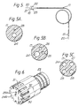
- This illustrates a typical known type of catheter which consists of a plastic tube 17 which has a handle 18 at one end and a tip member 19 at the other.
- a guide wire 20 can be passed through the tube 17.
- the handle 18 is provided with an axially located aperture 21 through which the guide wire 20 can pass.
- the handle is also provided with further radially located apertures 22 and 23.
- Figures 5A, 5B and 5C illustrate some known cross-sections for the catheter tube 17, these cross-sections being designed for different medical applications of the catheter.
- the tube 17 has a lumen or passage 24 to accommodate the guide wire 20 and a second lumen or passage 25 to accommodate micro-coaxial wiring.
- the tube 17 has lumens 24 and 25 as in Figure 5A but also has a third lumen 26 through which compressed air or other appropriate gas can be passed to inflate a balloon built into the end of the catheter tube 17 at or near its tip 19.
- a third lumen 26 through which compressed air or other appropriate gas can be passed to inflate a balloon built into the end of the catheter tube 17 at or near its tip 19.
- lumens 24 and 25 are intended to accommodate a fibre-optic channel for the application of laser angioplasty in known manner.
- the lumen 28 is intended to accommodate a pressure sensor (not shown) in known matter.
- the catheter(s) shown generally in Figures 5, 5A, 5B and 5C are of known construction.
- a catheter according to the present invention is characterised by the construction of the tip 19 or probe.
- Figures 6 - 8 illustrate examples of the tip 19 or probe according to the present invention.
- the tip 19 of the present invention is made of a plastic material such as polyvinylchloride (p.v.c.) and has a core section 29 through which lumens 24 a and 25 a pass.
- the core section 29 has twelve grooves 30 formed around its circumference, each groove being adapted to accommodate a single piezo-electric crystal transducer element 31.
- Each groove 30 is connected to the lumen 25 a by a passage 32.
- a micro-coaxial cable extends from the aperture 22 in the handle 18, through the catheter tube 17 and its constituent strands terminate at the transducer elements 31.
- the tip 19 has a spigot portion 33 which is shaped and dimensioned to be a friction fit in a cup-shaped end 34 to the catheter tube 17.
- the tip 19 can thus be designed with the appropriate number and location of lumens to match up with the known types of catheter tube 17.
- the junction between the spigot 33 and the inner surface of the cup shaped end 34 would be sealed by epoxy resin.
- the passages 32 would also be filled with epoxy resin.
- the approach for obtaining the required degree of resolution is to increase the number of transducer elements, e.g. by having one or more rings each of twelve transducer elements. Scanning of the organ is achieved by in effect electronically rotating a four-pole transducer element in relation to each ring.
- transducer elements would be mounted on a member which itself is rotatably mounted on the core section 29 of the probe.
- Some suitable drive means would be provided for rotating the member.
- the drive means could comprise a wire which passes back through the catheter tube 17 to itself be rotated by a suitable electric motor, for example.
- the connection between the wire and the member could take various forms.
- the advantage of having a rotatable transducer arrangement is that the same image resolution can be achieved with fewer transducer elements compared with Figures 3, 4, 6 and 7 or a higher resolution can be achieved for a given number of transducer elements.
- the degree of resolution will depend on the number of transducer elements carried by the rotatable member and the speed of rotation of that member, generally the higher the speed the higher the resolution.
- FIG 8 is a view similar to Figure 6 but showing an alternative form of the transducer arrangement.
- the transducer arrangement consists of a single ring or annulus 35 of piezo-electric crystal which has grooves 36 which extend parallel to the axis of the tip 19 and adjacent pairs of which define the transducer elements A, B, C etc ( Figures 3 and 4).
- a smooth tubular sheath 37 of ultrasonically transparent material covers the transducer assembly in order to facilitate the insertion and movement of the catheter through the artery.
- This additional transducer arrangement is designed to emit relatively low-frequency ultrasonic signals which will have the effect of causing the plaque to resonate and thus disintegrate.
- transducer arrangement can take a number of forms, two alternatives of which are shown in Figure 9.
- the first alternative consists of a single transducer element 39 mounted on the end face of the core section 29, the transducer element 39 having a concave surface 39a so that it will focus the ultrasonic emitted signals at a substantially axial point in relation to the core member 29.
- the alternative further transducer arrangement consists of a number of transducer elements 40 mounted around the outside surface of the core member 29 so that they emit ultrasonic signals in a substantially radially outward direction in relation to the axis of the artery.
- the date received from the transducer assembly is in the form of "snap-shots" as each of the sets of four transducer elements is fired and the associated echo signals received.
- These signals and associated echoes in effect give the instantaneous radial distance of points of the inside of the artery and points through the thickness of the arterial wall from the transducer elements that have been fired.
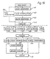
- This step- is shown at 41 in Figure 10 and labelled “SLICE GENERATION”, each firing and associated echoes representing a "slice” through the artery.
- this "slice” is produced by a finite number of transducer elements it does not give a complete picture of the cross-section of the artery but only an approximation to that cross-section.
- Interpolation between adjacent "slices” can be achieved, for example, by known so-called spatial correlation techniques. This involves comparing the spacial features of individual "slices” using similar mathematics to those used for cross-correlation functions employed in time series analysis.
- the software of the present invention digitises each "slice” and stores the image information of each "slice” in terms of the basic picture elements or pixels.
- the three-dimensional model is then constructed from the digitised “slices” which are of course in the correct sequence, the three-dimensional model being made up of so-called “voxels” (three-dimensional "pixels") thus allowing the details of irregular anatomical lesions to be accurately modelled.
- This is in contrast with known commercially available software for three-dimensional solid modelling which is based on the concept of modelling an object using simple geometric shapes called “primitives” which are in effect taken from a library of pre-determined shapes. Further information on this known approach can be found in "Principles of Interactive Computer Graphics" by Foley and Van Dam, published by Prentice-Hall in 1982.
- the next step is to in effect integrate the various interpolated slices of the artery in order to produce a representation of the artery in three dimensions, this step being referred to as "VOLUME GENERATION" and indicated at 43 in Figure 10.
- the manipulation "INTERSECT” refers to taking two three-dimensional representations and combining them for example in order to provide a visual representation of a Y-shaped artery.
- the manipulation referred to as "ERASE” is concerned with removing part of the three-dimensional representation and the manipulation referred to as "OPEN” is concerned with in effect notionally cutting the artery in a longitudinal direction and opening it up flat so that the interior of the artery can be seen in terms of contours.
- An important advantage of the present invention lies in its power and flexibility to slice the solid three-dimensional representation or model (contained in three-dimensional "voxel" space) in any orientation. Hence any of a number of two-dimensional slices can be reproduced and further image processing of each slice undertaken to, for example, enhance certain features of the tissue.
- Figure 10 illustrates the different ways in which the three-dimensional representations can actually be displayed.
- the representation can be presented in the form of a simulated X-ray picture i.e. with the background darker than the foreground. This is represented at 52 in Figure 10.
- the boxes marked 53, 56 and 57 in Figure 10 indicate different ways in which the image can be coloured.
- the box 55 labelled "TRANSPARENCY" refers to the possibility of presenting an image which has a uniform tone.
- the software is written in a high level language, e.g. FORTRAN 77 running under VMS 4.4., and has a large range of features some of which have already been described with reference to Figure 10.
- the software has been written in a form which is entirely menu driven and control of the system would preferably be effected via a "mouse" with the rotation of the images being controlled by analogue controls.
- the computer 10 could be provided with an array processor in order to speed up the processing of the data, thus enabling the user to rotate a three-dimensional model image in real time, although the image itself has, as indicated earlier, been generated in non-real-time.
- the software interface between the FORTRAN programmes and the terminal 12 consists of a series of routines for controlling the terminal.
- these routines form a library called WKS77 which is like the system known as GKS (Graphical Kernel System).
- the processing diagrammatically illustrated below the dotted line can be used to manipulate and display any image produced by the steps indicated above the dotted line.
- the steps above the dotted line are concerned with generating data representative of a three-dimensional item such as an artery but the software below the dotted line can be used to manipulate data which is representative of other things.
- the probe already described could be used to generate signals which are indicative of the blood flow within an artery and this data could be processed and manipulated to give a visual representation of that blood flow. This possibility is shown diagrammatically by the box marked "FLOW VISUALISATION" at 58 in Figure 10.
- Figure 11 illustrates diagrammatically the steps involved in the "FLOW VISUALISATION" indicated at 58 in Figure 10.
- the present invention is to be used to visualise the interior of organs having a significantly greater internal dimension than an artery it is possible to construct the probe with a much greater external diameter.
- the invention can be used to produce trans-oesophagal, trans-vaginal, trans-urethral and trans-rectal imaging.
- each annulus could accommodate a larger number of transducer elements. By this means an increase in resolution is achieved.
- an arrangement of transducer elements as shown in Figures 12 and 13 could be employed which could enable so-called tissue characterisation data to be obtained.
- two crystals 59 a and 59 b of a pair are inclined towards one another so that ultrasonic signals emanating from them focus at a common point 60 radially outwardly from the position of the crystals.
- Each crystal of a pair operates at a different ultrasonic frequency from the other crystal of the pair. This can be achieved by variations in the crystal thickness.
- the probe wall is indicated at 62.
- the gap 61 between adjacent crystals of a pair together with the indentation formed between them would preferably be filled by a material which is transparent to ultrasonic frequencies, for example an epoxy resin 62 a .
- a material which is transparent to ultrasonic frequencies for example an epoxy resin 62 a .
- the purpose of this is to produce a smooth surface to facilitate the passage of the transducer arrangement through the body of the patient.
- crystals would be energised and the echo signals transmitted back by means of micro-coaxial cables of the kind referred to in connection with Figures 7 and 9.
- the system of the present invention as previously described will give the medical practitioner a picture of the internal organ as the catheter passes through it. However, this will be a very localised picture and will not provide the medical practitioner with an overall view as to exactly where the probe at the end of the catheter is located within the arterial system of the patient's body.
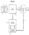
- Figure 14 illustrates in diagrammatic form an arrangement whereby the system of the present invention, already described, is combined with a known X-ray system to in effect superimpose the image provided by the present invention on the overall X-ray image provided by the known system.
- the medical practitioner is provided with a very convenient means for gaining an accurate overall picture.
- the linking of the two systems could also enable tissue characterisation to be obtained.
- Figure 14 illustrates diagrammatically one way in which the two systems could be integrated.
- the system of the present invention as shown to the right of the broken line in Figure 1 is generally indicated at 63 and 64 in Figure 14 the catheter and probe being indicated by 1 and 2 respectively within an artery 69 of the patient.
- a known X-ray source is indicated at 65 and a known X-ray transducer at 66.
- the computer 63 connects the system of the present invention to the known X-ray system 67 in such a way that the output from the X-ray system 67 is a combined image 70 which includes the X-ray image 69 1 and an image 2 1 of the probe 2 within the arterial system of the patient.
- the known X-ray system 67 is referred to as an X-RAY digital subtraction angiography or DSA IMAGING SYSTEM in the art.
- the system described with reference to Figure 14 operates in accordance with the internationally accepted ACR NEMA (American College of Radiology, National Equipment Manufacturers Association) standard for imaging systems and can therefore readily import images from any other system which is formatted under the ACR NEMA protocols.
- ACR NEMA American College of Radiology, National Equipment Manufacturers Association
- a simple interface preferably parallel though not necessarily so between the system computer of the present invention and that of the DSA system (typically a VAX) will permit DSA images to be imported and displayed on the system of the present invention together with the ultrasound images generated by the latter system.
- the controlling of the firing of the elements in the transducer assembly is effected via the computer data bus 71.
- the resultant echo signals are fed via the data bus 72.
- a characteristic pattern of X-ray opaque dots are provided on the tip of the catheter to allow its precise position to be automatically located within the DSA image.
- template matching or other pattern recognition procedures could be used.
- the precise location of the catheter can be determined in three dimensions. This information can be used to build a full three-dimensional image from the composite scans of the system and also for the automatic co-relation of the ultrasound and DSA image data for visualisation and/or tissue characterisation.
- a further advantage of this arrangement is that it permits the easy X-ray detection of the catheter tip should it become detached from the body of the catheter during its use.
- FIGS. 14 illustrate an alternative method to that shown in Figure 14 for identifying the position of the catheter 1 within the body of the patient.
- the catheter 1 is provided with a spark generating arrangement 73 so that when energised the resulting spark will be detected by means of an electrode array 74 which consists of four plates 74 a , 74 b , 74 c and 74 d .
- the strength of signal generated by the plates in response to the spark will be a function of the distance of the spark from the particular plate. In this way the sum of the signals of the four plates will enable the position of the probe to be determined.
- the patient's body is diagrammatically illustrated at 75.
- Figure 17 illustrates diagrammatically a system which enables an approximate and less accurate assessment of the position of the probe within the patient to be made based entirely on measuring the distance that the probe has been inserted into the body of the patient.
- this arrangement involves the use of an electronic micrometer and stepping motor assembly 76 which, in operation, moves the catheter into the patient and generates an electrical signal indicative of the distance the catheter has been inserted.
- the electronic micrometer could be used without the motor because instead of the latter the catheter could be inserted manually.
- the signals from the electronic micrometer 76 are fed via an interface 77 to the system computer (63 in Figure 14).
- Figure 17 illustrates other interfaces between the catheter and the electronic signal processing system shown to the right of the broken line in Figure 1.
- the main and essential interface is shown at 78 between the microcoaxial cables in the catheter and the system.
- interface 79 relates to the fibre-optic channel in lumen 27 in Figure 5C for the application of laser angioplasty the fibre optic cable being represented at 79 a ;
- interface 80 relates to the pressure sensor in lumen 28 (Figure 5C) the connecting microcoaxial cable being shown at 80 a ;
- interface 81 relates to the guide wire 20 in lumen 24 of Figure 5A the channel for the wire being shown at 81 a ;
- interface 82 relates to the angioplasty balloon lumen 26 of Figure 5B the channel for the balloon being shown at 82 a .
- Interface 83 is concerned with the insertion of a fluid, such as a saline solution into the catheter and/or a dye in order to create contrast in the X-ray picture the associated channel being indicated at 83 a .
- a fluid such as a saline solution
- Interface 84 is concerned with the measuring of blood flow using the Doppler principle already described with reference to 58 in Figure 10, the connecting coaxial cable being shown at 84 a .
- the third aspect of the invention illustrated in Figure 17 relates to a means for automatically identifying the type of catheter being used and thereby automatically setting up the appropriate parameters in the system so that the correct signals are sent to the probe on the catheter and the resulting echoes are processed in the appropriate manner.
- the end of the catheter which is adapted to be connected to the system (known in the art as the "proximal” end or interface) is provided with some means which is characteristic of that catheter and which can be “interrogated” by the system.
- the catheter has characteristics which render it “intelligent”.
- This can be achieved in a number of ways but preferably by incorporating a ROM (read-only-memory) integrated circuit 86 in the proximal end of the catheter. This ROM would have built into it all the necessary characteristics of the particular catheter so that when connected to the system it can be interrogated by it.
- the characteristics which could be built into the ROM could include the following;
- the ROM can incorporate any information which is characteristic of a particular catheter/probe so that the system can be automatically pre-set by the mere connection of the catheter to the system.
- ROM read only memory
- proximal interface i.e. the point at which the catheter is connected to the system as distinct from the distal end of the catheter i.e. that end which carries the probe 2.
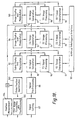
- Figure 18 is a schematic diagram illustrating the manner in which all the information which can be generated by the system is processed to produce displays to assist the medical practitioner.
- system of the present invention as illustrated in Figure 1, can be used to present the information to the medical practitioner in one-dimensional, two-dimensional and three-dimensional form.
- the echo signals can be used to indicate merely that plaque is there because of the attenuated or modulated reflection which it gives compared with the wall proper of the artery; this is the one-dimensional form referred to and labelled "ID" in Figure 18.
- echo signals from the transducer assembly carried by the probe 2 are sorted at 87 and pre-processed at 88. They are then fed to a one-dimensional signal generator 89 so that these signals which will give the one-dimensional information referred to earlier are produced. These can be processed at 90, displayed and manipulated at 92 and used to give a tissue characterisation at 91.
- echo signals characteristic of the two and three-dimensional visualisations are generated at 93 and 97 respectively, processed at 94 and 98, displayed and manipulated at 96 and 100 and used for tissue characterisation at 95 and 99 respectively.
- the tissue characterisation information at 91, 95 and 99 can be fed to an expert system or artificial intelligence system through the interface indicated at 101 whereby an automatic diagnosis of the medical condition is made.
- FIG. 18 Also represented in Figure 18 at 102 is the DSA System of Figure 14, shown at 102, whereby the position of the probe 2 can be fed into the 3D Image Generation 97 through a Probe Position Identification step 103.
- the simpler and less informative electronic micrometer means for indicating the position of the probe, and represented at 104, can be fed into 97.
Landscapes
- Engineering & Computer Science (AREA)
- Physics & Mathematics (AREA)
- Health & Medical Sciences (AREA)
- Remote Sensing (AREA)
- Life Sciences & Earth Sciences (AREA)
- Radar, Positioning & Navigation (AREA)
- Acoustics & Sound (AREA)
- Public Health (AREA)
- General Physics & Mathematics (AREA)
- Biomedical Technology (AREA)
- Heart & Thoracic Surgery (AREA)
- Medical Informatics (AREA)
- Molecular Biology (AREA)
- Surgery (AREA)
- Animal Behavior & Ethology (AREA)
- General Health & Medical Sciences (AREA)
- Pathology (AREA)
- Veterinary Medicine (AREA)
- Nuclear Medicine, Radiotherapy & Molecular Imaging (AREA)
- Biophysics (AREA)
- Radiology & Medical Imaging (AREA)
- Computer Networks & Wireless Communication (AREA)
- Gynecology & Obstetrics (AREA)
- Mechanical Engineering (AREA)
- Ultra Sonic Daignosis Equipment (AREA)
- Processing Of Meat And Fish (AREA)
- Magnetic Resonance Imaging Apparatus (AREA)
- Investigating Or Analyzing Materials By The Use Of Electric Means (AREA)
- Other Investigation Or Analysis Of Materials By Electrical Means (AREA)
- Apparatus For Radiation Diagnosis (AREA)
- Measuring And Recording Apparatus For Diagnosis (AREA)
- Image Processing (AREA)
- Endoscopes (AREA)
Abstract
Description
- The present invention relates to methods and apparatus for the examination and treatment of internal organs of the human body.
- It is already known to make an internal examination of an internal human organ, without recourse to surgery, by means of optically based equipment and also by means of equipment which makes use of the transmission and receipt of ultrasonic signals. The present invention is concerned with the latter approach and with providing a system and apparatus which will enable the shortcomings of existing equipment to be overcome thus providing the medical practitioner and hence the patient with the opportunity for a more accurate and timely diagnosis and hence treatment.
- As indicated earlier it is known to use ultrasonic signals in order to create a visual representation of the interior of an internal human organ. In one known method a probe capable of emitting and receiving an ultrasonic signal is moved over the outside of the human body and a continuous two-dimensional visual representation of the internal cross-section of the human organ is generated from the ultrasonic signals reflected or attenuated by the organ. Whilst such equipment is easy to operate the visual representation of the interior of the organ is not very accurate and in any event is in only two dimensions.
- The known prior art approaches to the problem of providing the medical practitioner with an accurate and useful visual representation of the interior of the human organ have concentrated on producing a real-time continuous two-dimensional image. This approach has inherent disadvantages which become particularly acute where it is desired to make an internal examination of an organ having a relatively small cross-section, in particular a human artery.
- The present invention approaches this problem from the unexpected appreciation that a continuous real-time image is not necessary in order to enable the medical practitioner to obtain a clear internal picture of the organ.
- There is disclosed in US patent no. 4,672,963 an ultrasonic system for visualising the internal organs of a human body and in particular the prostate gland. The system disclosed employs a digital computer by which a 3-D representation of the organ may be obtained together with a representation of its internal structure including a visual representation of the tissues making up that organ. There is disclosed in IEEE Transactions on Medical Imaging of March 1986,
No 1, at pages 45-47 an arrangement which is concerned with the 3-D reconstruction of original surfaces from tomograms and shows 3-D images made up of "voxels". In this disclosed arrangement a voxel scene is produced from a stack of tomograms by linear interpolation between the original plains. This paper is mainly concerned with the determination of a boundary between tissues of different densities from a 3-D display made up of voxels. - According to the present invention apparatus for providing an image of the interior of a human organ comprises a combination of the following features:
- (a) a catheter (1) for insertion into the human body;
- (b) an ultrasonic transducer assembly (2) mounted on the catheter;
- (c) means (6) for energising the transducer assembly to generate ultrasonic signals;
- (d) means (7) for receiving the resultant ultrasonic echo signals;
- (e) means (8) for converting the echo signals into digital signals;
- (f) a digital computer (10) to which the digital signals are fed;
- (g) means (12) for visually displaying the interior of the organ; characterised in that there are:
- (h) means for obtaining a first approximation to the instantaneous cross-sectional shape or "slice" of the organ by means of the said echo signals;
- (i) means for digitising each "slice" into two-dimensional elements or "pixels";
- (j) means for interpolating between the points on the cross-section defined by the said echo signals to provide a second approximation to the said instantaneous cross-sectional shape or "slice";
- (k) integrating a plurality of the thus generated "slices" and interpolating between adjacent "slices" to form a three-dimensional representation which is now made up of three-dimensional elements or "voxels"; and
- (l) stored programme control means for manipulating the said three-dimensional elements or "voxels" to produce a variety of three-dimensional representations of the organ including its shape and structural make-up.
-
- According to the present invention a method for providing an image of the interior of a human organ comprises the following combination of steps:
- a) energising (6) a transducer assembly located in the human body to generate ultrasonic signals;
- (b) receiving (7) the resultant ultrasonic echo signals;
- (c) converting (8) the echo signals into digital signals;
- (d) supplying the digital signals to a digital computer (10);
- (e) visually displaying (12) the interior of the organ; characterised by the steps of:
- (f) obtaining a first approximation to the instantaneous cross-sectional shape or "slice" of the organ by means of the said echo signals;
- (g) digitising each "slice" into two-dimensional elements or "pixels";
- (h) interpolating between the points on the cross-section defined by the said echo signals to provide a second approximation to the said instantaneous cross-sectional shape or "slice";
- (i) integrating a plurality of the thus generated "slices" and interpolating between adjacent "slices" to form a three-dimensional representation which is now made up of three-dimensional elements or "voxels"; and
- (j) manipulating the said three-dimensional elements or "voxels" to produce a variety of three-dimensional representations of the organ including its shape and structural make-up.
-
- How the invention may be carried out will now be described, by way of example only, and with reference to the accompanying drawings in which:
- Figure 1 is a block diagram of a system according to the present invention;
- Figure 2 illustrates the timing of the "burst" and "echo" signals of Figure 1;
- Figures 3A and 3B are diagrammatic representations of a single annulus transducer arrangement and its associated electrical wiring.
- Figure 4 is a view similar to Figure 3B showing the wiring of a transducer arrangement having two annuli;
- Figure 5 shows a known construction of catheter for use in the system of Figure 1;
- Figures 5A, 5B, and 5C are cross-sections illustrating different types of known catheter for different purposes;
- Figure 6 is a perspective view showing one form of the ultrasonic transducer assembly for mounting on the end of a catheter;
- Figure 7 is a longitudinal section taken on the line A-A of Figure 6;
- Figure 8 is a view similar to Figure 6 showing an alternative construction of ultrasonic transducer assembly;
- Figure 9 is a view similar to Figure 7 illustrating a transducer assembly which is designed to provide treatment as well as diagnosis;
- Figure 10 is a flow diagram showing the logic of the software/programming used in the system of Figure 1; and
- Figure 11 is a flow diagram illustrating in more detail a modification or enhancement of the software illustrated in Figure 10.
- Figure 12 is a diagrammatic cross sectional view of a further construction of ultrasonic transducer assembly;
- Figure 13 is a fragmentary enlarged view of part of the transducer assembly of Figure 12;
- Figure 14 is a diagrammatic representation of a way of coupling the system of the present invention to a known X-ray system to indicate the position of the ultrasonic transducer assembly within the patient's body;
- Figure 15 is a diagrammatic representation of an alternative to Figure 14 for indicating the position of the ultrasonic transducer assembly within the patient's body using a spark discharge;
- Figure 16 is an enlarged sectional view of the end of the probe shown in Figure 15;
- Figure 17 is a schematic illustration of both the interface between the catheter and the echo signal processing system to the right of the broken line in Figure 1 and also a further means for indicating the position of the probe within the patient's body using a micrometer; and
- Figure 18 is a block diagram showing in more detail that part of the system shown at 10, 11 and 12 in Figure 1.
-
- Figure 1 is a block diagrammatic representation of a method for providing an image of the interior of a human organ particularly an artery.
- A
catheter 1 for insertion into ahuman artery 3 has a free end 1a on which is mounted an annularultrasonic transducer assembly 2, the other end of the catheter being electrically connected by connection 4 to the equipment shown to the right of the broken line in Figure 1. - The electrical connection 4 is described in detail in connection with Figures 3 and 4 but in effect includes a wiring arrangement which acts as a multiplexer/demultiplexer 5 which functions to reduce the number of wires which would otherwise need to pass through the
catheter 1 in order to connect thetransducer assembly 2 to the equipment illustrated diagrammatically to the right of the broken line in Figure 1. - The
transducer assembly 2 is energised by a driving circuit 6 to cause thetransducer assembly 2 to emit ultrasonic signals. Thetransducer assembly 2 responds to echoes of the emitted signals and this causes the generation of echo signals which pass back through the multiplexer/demultiplexer arrangement 5 to anultrasonic receiving circuit 7 and then to an analogue-to-digital converter 8 which translates the analogue electrical echo signals into digital signals. - These digital echo signals are then fed to a fast-in-fast-out data store 9 from whence they are fed into a
digital computer 10. - The
digital computer 10 is programmed by means of software 11 in such a way that the digital echo signals are transformed into signals which when fed to a high resolution graphics display terminal 12 will enable a three-dimensional representation of the interior of theartery 3 to be displayed. - The software 11 enables the data to be manipulated so that the three-dimensional representation can be viewed from different aspects.
- A hard copy of the three-dimensional representation can be obtained by means of a
printer 13. - The multiplexer/demultiplexer arrangement 5 could consist of a multiplexer/demultiplexer circuit as such or could comprise a logic wiring arrangement two examples of which are shown in Figures 3 and 4 later. If a multiplexer/demultiplexer circuit as such were used it could be constructed from a standard analogue switch array such as the Siliconix types SD5400, SD5401 or SD5402 DMOS FET Quad.
- The ultrasonic driving circuit 6 and receiving
circuit 7 could be of the kind disclosed by Donald W Baker in his paper entitled "Pulsed Ultrasound Doppler Blood Flow Sensing", IEEE Transactions on Sonics and UltrasonicsVol SU17 No 3 1970. - The analogue to
digital converter 8 could be of the type disclosed in Datel Corporation's Application Note DTL-18. - The fast-in-fast-out store 9 could be of the kind disclosed by J E Pedersen in his article entitled "Fast Dedicated Microprocessor for Real Time Frequency Analysis of Ultrasound Blood Velocity Measurements": Medical and Biological Engineering and
Computing Vol 20 pages 681 - 686. - The
digital computer 10 would be of any suitable kind and capacity such as a DEC Micro Vax-II having eight megabytes of RAM, 70 megabytes of hard disk and a 90 megabyte tape streamer. The connection between thedigital computer 10 and the high resolutioncolour graphics terminal 12 is made via a 16-bit parallel interface. - The high resolution
colour graphics terminal 12 is fitted with 8 planes, has a maximum spacial resolution of 1448 (X) by 1024 (Y) at a depth resolution of 8 bits (256 colours). If required the depth resolution can be increased up to as many as 24 bits, although in detriment to the spacial resolution. All the programmes used in the software 11 in use assume 256 colours and 1448 x 1024 pixels. Examples of terminals which meet these requirements are the Sigmex 6200 series, and certain types of Tektronix and Ramtech terminals. - In order to give an overall appreciation of how the method illustrated in Figure 1 operates there will now follow a brief description although aspects of the method will then be described in more detail in relation to the remaining figures in the drawings.
- The geometry and construction of the probe carrying the
annular transducer assembly 2 is selected and designed to be compatible with the nature and flow of the fluid within theartery 3 and with the internal diameter of that artery. Each piezo-electric element of the transducer assembly is connected once per scan for less than 100 µS through the multiplexer/demultiplexer arrangement 5 to the ultrasonic driving and receivingcircuits 6 and 7 respectively. A 1 µS burst of high frequency signal from the driving circuit 6 pulses the selected piezo-electric crystal. The resulting ultrasonic pressure wave produced by the crystal is emitted radially to insonate the internal wall of theartery 3. Echoes from this interface, and other acoustic impedence discontinuities in the sound path, are received by the same piezo-electric crystal element. The pulse-echo signal after amplification by the receivingcircuit 7 is combined with a "start-of-scan" pulse and with a switching circuit pulse. This composite radio frequency signal is then digitised by a "flash" analogue todigital converter 8, i.e. a converter which can handle high frequency signals. The resultant 8 bit samples are then stored simultaneously in a high speed random-access-memory. - When a complete scan by all the elements of the transducer assembly have been stored, the date is down-loaded through a parallel data link to the
digital computer 10. Thedigital computer 10 runs sophisticated signal processing and reconstruction software 11 to create a high resolution image of the artery cross-section, or other aspect, on a high resolution colour graphics display terminal. - The frequency of energisation of the transducer elements would preferably lie in the
range 1 to 20 MHz the axial length of each of the transducer elements is preferably between 2mm and 8mm. The best results have been obtained with a length of 8mm. - This illustrates the ultrasonic signals fired by the transducer elements and their associated echo signals. Specifically the ultrasonic signals are indicated at 14a to 14j inclusive and the associated echo signals at 15a to 15j inclusive, synchronising pulses being indicated at 16a to 16j inclusive.
- As mentioned in connection with Figure 1 the
transducer assembly 2 comprises a number of transducer elements each of which consists of a piezo-electric crystal preferably made of lead zirconium titanate (PZT). In Figure 1 four such elements are illustrated and Figure 2 is based on the assumption that there are ten transducer elements. The number of elements can vary but the higher the number the greater the resolution or clarity of the image that will be produced. - Figures 3 and 4 illustrate in more detail two specific arrangements of transducer elements and the way in which they are connected electrically in order to reduce the number of wires which have to pass along the tubular catheter 4, i.e. the wiring arrangements illustrated act in effect as a multiplexer/demultiplexer.
- In Figure 3 the transducer arrangement consists of twelve transducer elements labelled A1, B1, C1, A2, B2, C2, A3, B3, C3, A4, B4, C4 taken in a clockwise direction. The elements A1, A2, A3, A4 are electrically connected in parallel so that they are energised at the same time (see also Figure 1). The four elements B1, B2, B3, B4 are similarly connected to be energised together as are the elements C1, C2, C3, and C4, as illustrated.
- In operation four elements are energised at a time in the order A1, A2, A3, A4 together, then B1, B2, B3, B4 together, then C1, C2, C3, C4 together, and so on. With the wiring arrangement shown in Figure 3B although there are twelve transducer elements there are only four wire leading through the tubular catheter to energise them. This wiring arrangement thus acts as the equivalent of a multiplexer/demultiplexer circuit.
- In Figure 4 the transducer arrangement consists of two side-by-side annuli each of twelve transducer elements, as compared with Figure 3 in which there is only a single annulus of twelve elements. The wiring arrangement of each of the two annuli is similar to that of Figure 3 but the elements of the two annuli are interconnected so that on each firing pulse four elements from each annulus are energised together, i.e. eight elements are energised at a time.
- The sequence of energising the transducer elements is as follows. The group Al elements in the first ring are energised together with the group B2 elements in the second ring. The group B1 elements in the first ring are energised with the group C2 elements in the second ring. The group C1 elements in the first ring are energised with the group A2 elements in the second ring.
- It will be noted that immediately adjacent elements in the two rings are not energised together e.g. A1 with a A2. The reason for this is to reduce the likelihood of cross-talk between the two rings.
- More than two rings could be used in which case non-adjacent rings could have equivalent transducer elements fired together because the risk of cross-talk would already have been reduced by the spacing apart of these two rings by an intermediate ring or rings.
- This illustrates a typical known type of catheter which consists of a
plastic tube 17 which has ahandle 18 at one end and atip member 19 at the other. Aguide wire 20 can be passed through thetube 17. Thehandle 18 is provided with an axially locatedaperture 21 through which theguide wire 20 can pass. The handle is also provided with further radially locatedapertures - Figures 5A, 5B and 5C illustrate some known cross-sections for the
catheter tube 17, these cross-sections being designed for different medical applications of the catheter. - In the cross-section of Figure 5A the
tube 17 has a lumen orpassage 24 to accommodate theguide wire 20 and a second lumen orpassage 25 to accommodate micro-coaxial wiring. - In the cross-section of Figure 5B the
tube 17 haslumens third lumen 26 through which compressed air or other appropriate gas can be passed to inflate a balloon built into the end of thecatheter tube 17 at or near itstip 19. Such a construction of catheter is well known. - In the cross-section of Figure 5C there are
lumens further lumens Lumen 27 is intended to accommodate a fibre-optic channel for the application of laser angioplasty in known manner. Thelumen 28 is intended to accommodate a pressure sensor (not shown) in known matter. - The catheter(s) shown generally in Figures 5, 5A, 5B and 5C are of known construction. A catheter according to the present invention is characterised by the construction of the
tip 19 or probe. Figures 6 - 8 illustrate examples of thetip 19 or probe according to the present invention. - In Figures 6 and 7 the
tip 19 of the present invention is made of a plastic material such as polyvinylchloride (p.v.c.) and has acore section 29 through which lumens 24a and 25a pass. Thecore section 29 has twelvegrooves 30 formed around its circumference, each groove being adapted to accommodate a single piezo-electriccrystal transducer element 31. - Each
groove 30 is connected to the lumen 25a by apassage 32. A micro-coaxial cable extends from theaperture 22 in thehandle 18, through thecatheter tube 17 and its constituent strands terminate at thetransducer elements 31. - The
tip 19 has aspigot portion 33 which is shaped and dimensioned to be a friction fit in a cup-shapedend 34 to thecatheter tube 17. Thetip 19 can thus be designed with the appropriate number and location of lumens to match up with the known types ofcatheter tube 17. In practice because each catheter tube is used only once, and also because of the requirement to provide a medically safe construction, the junction between thespigot 33 and the inner surface of the cup shapedend 34 would be sealed by epoxy resin. Furthermore, thepassages 32 would also be filled with epoxy resin. - In Figures 6 and 7 (and Figures 3 and 4) the approach for obtaining the required degree of resolution is to increase the number of transducer elements, e.g. by having one or more rings each of twelve transducer elements. Scanning of the organ is achieved by in effect electronically rotating a four-pole transducer element in relation to each ring.
- An alternative approach involves the physical rotation of the transducer elements to achieve the same objective. In this approach the transducer elements would be mounted on a member which itself is rotatably mounted on the
core section 29 of the probe. Some suitable drive means would be provided for rotating the member. The drive means could comprise a wire which passes back through thecatheter tube 17 to itself be rotated by a suitable electric motor, for example. The connection between the wire and the member could take various forms. - The advantage of having a rotatable transducer arrangement is that the same image resolution can be achieved with fewer transducer elements compared with Figures 3, 4, 6 and 7 or a higher resolution can be achieved for a given number of transducer elements. The degree of resolution will depend on the number of transducer elements carried by the rotatable member and the speed of rotation of that member, generally the higher the speed the higher the resolution.
- Figure 8 is a view similar to Figure 6 but showing an alternative form of the transducer arrangement. In this alternative form the transducer arrangement consists of a single ring or
annulus 35 of piezo-electric crystal which hasgrooves 36 which extend parallel to the axis of thetip 19 and adjacent pairs of which define the transducer elements A, B, C etc (Figures 3 and 4). A smoothtubular sheath 37 of ultrasonically transparent material covers the transducer assembly in order to facilitate the insertion and movement of the catheter through the artery. - This is a view similar to Figure 7 but in this embodiment the probe or tip at the end of the catheter is provided with a further piezo-electric transducer arrangement, the purpose of which is to break up or disintegrate plaque which has formed on the inside of the artery.
- This additional transducer arrangement is designed to emit relatively low-frequency ultrasonic signals which will have the effect of causing the plaque to resonate and thus disintegrate.
- This additions transducer arrangement can take a number of forms, two alternatives of which are shown in Figure 9.
- The first alternative consists of a
single transducer element 39 mounted on the end face of thecore section 29, thetransducer element 39 having a concave surface 39a so that it will focus the ultrasonic emitted signals at a substantially axial point in relation to thecore member 29. - The alternative further transducer arrangement consists of a number of
transducer elements 40 mounted around the outside surface of thecore member 29 so that they emit ultrasonic signals in a substantially radially outward direction in relation to the axis of the artery. - This illustrates the logic of the software which is shown schematically at 11 in Figure 1.
- As indicated earlier the date received from the transducer assembly is in the form of "snap-shots" as each of the sets of four transducer elements is fired and the associated echo signals received. These signals and associated echoes in effect give the instantaneous radial distance of points of the inside of the artery and points through the thickness of the arterial wall from the transducer elements that have been fired. This step- is shown at 41 in Figure 10 and labelled "SLICE GENERATION", each firing and associated echoes representing a "slice" through the artery. However, because this "slice" is produced by a finite number of transducer elements it does not give a complete picture of the cross-section of the artery but only an approximation to that cross-section. It is therefore necessary to interpolate between the points on the cross-section that have been ascertained by the signals fired from and received by the individual transducer elements and to interpolate between adjacent "slices". This interpolation step is indicated at 42 in Figure 10 and labelled "SLICE INTERPOLATION".
- Interpolation between adjacent "slices" can be achieved, for example, by known so-called spatial correlation techniques. This involves comparing the spacial features of individual "slices" using similar mathematics to those used for cross-correlation functions employed in time series analysis.
- The software of the present invention digitises each "slice" and stores the image information of each "slice" in terms of the basic picture elements or pixels. The three-dimensional model is then constructed from the digitised "slices" which are of course in the correct sequence, the three-dimensional model being made up of so-called "voxels" (three-dimensional "pixels") thus allowing the details of irregular anatomical lesions to be accurately modelled. This is in contrast with known commercially available software for three-dimensional solid modelling which is based on the concept of modelling an object using simple geometric shapes called "primitives" which are in effect taken from a library of pre-determined shapes. Further information on this known approach can be found in "Principles of Interactive Computer Graphics" by Foley and Van Dam, published by Prentice-Hall in 1982.
- The advantages of the approach adopted by the present invention (i.e. using "voxels") is that it is then possible to rapidly manipulate the representation and take sections through it etc because the orientation of each individual "voxel" making up the total representation or model is not critical since each one is so small in relation to the total representation. This contrasts with the known method using "primitives" where the sizes of the latter are significant in relation to the total representation and consequently their orientations are critical to the obtaining of an accurate representation or model and therefore each "primitive" would have to be individually re-oriented during each manipulation of the representation or model.
- The next step is to in effect integrate the various interpolated slices of the artery in order to produce a representation of the artery in three dimensions, this step being referred to as "VOLUME GENERATION" and indicated at 43 in Figure 10.
- After this has been done the data representing the three-dimensional image of the artery can be handled or manipulated in a number of ways in order to provide different aspects of that three-dimensional image. This step is indicated in Figure 10 by
box number 44 labelled "HANDLING". - In Figure 10 the steps illustrated below the broken line are all concerned with the different manipulations that can be carried out on the three-dimensional representation that has already been produced by means of the steps above the dotted line. More specifically the steps labelled "ROTATE", "CUT", "INTERSECT", "UNITE", "ERASE" and "OPEN" are all concerned with manipulating the three-dimensional representation in a particular way. Specifically "ROTATE" refers to rotating the three-dimensional representation so that it can be viewed from different angles. The manipulation "CUT" refers to in effect removing a segment of the three-dimensional representation so that the interior can be viewed at that particular point. The manipulation "INTERSECT" refers to taking two three-dimensional representations and combining them for example in order to provide a visual representation of a Y-shaped artery. The manipulation referred to as "ERASE" is concerned with removing part of the three-dimensional representation and the manipulation referred to as "OPEN" is concerned with in effect notionally cutting the artery in a longitudinal direction and opening it up flat so that the interior of the artery can be seen in terms of contours.
- An important advantage of the present invention lies in its power and flexibility to slice the solid three-dimensional representation or model (contained in three-dimensional "voxel" space) in any orientation. Hence any of a number of two-dimensional slices can be reproduced and further image processing of each slice undertaken to, for example, enhance certain features of the tissue.
- It should be emphasised that the various manipulations just described are only examples of those which could be carried out.
- The remainder of Figure 10 illustrates the different ways in which the three-dimensional representations can actually be displayed. For example the representation can be presented in the form of a simulated X-ray picture i.e. with the background darker than the foreground. This is represented at 52 in Figure 10. The boxes marked 53, 56 and 57 in Figure 10 indicate different ways in which the image can be coloured. The
box 55 labelled "TRANSPARENCY" refers to the possibility of presenting an image which has a uniform tone. - The software is written in a high level language, e.g.
FORTRAN 77 running under VMS 4.4., and has a large range of features some of which have already been described with reference to Figure 10. - The software has been written in a form which is entirely menu driven and control of the system would preferably be effected via a "mouse" with the rotation of the images being controlled by analogue controls.
- Furthermore the
computer 10 could be provided with an array processor in order to speed up the processing of the data, thus enabling the user to rotate a three-dimensional model image in real time, although the image itself has, as indicated earlier, been generated in non-real-time. - The software interface between the FORTRAN programmes and the terminal 12 consists of a series of routines for controlling the terminal. In the case of a Sigmex terminal these routines form a library called WKS77 which is like the system known as GKS (Graphical Kernel System).
- In Figure 10 the processing diagrammatically illustrated below the dotted line can be used to manipulate and display any image produced by the steps indicated above the dotted line. In Figure 10 the steps above the dotted line are concerned with generating data representative of a three-dimensional item such as an artery but the software below the dotted line can be used to manipulate data which is representative of other things.
- More specifically the probe already described could be used to generate signals which are indicative of the blood flow within an artery and this data could be processed and manipulated to give a visual representation of that blood flow. This possibility is shown diagrammatically by the box marked "FLOW VISUALISATION" at 58 in Figure 10.
- It is already known to use ultrasonic signals for the assessment of arterial disease by estimating the velocity of blood flow in an artery. These known systems make use of the Doppler principle.
- In the prior art approach pulses of ultrasonic signals cause multiple reflections from red blood cells flowing in the artery. In these systems only a small spacial section of the flow is analysed, this being referred to as the "sample volume" and is obtained by range gating the reflected ultrasonic signals. Further information on this prior art approach can be found in a paper entitled "Pulsed Ultrasound Doppler Blood Flow Sensing" by Donald W Baker in the IEEE Transactions on Sonics and Ultrasonics
Vol SU17 No 3 1970. In the present invention there will be multiple software range gates so that flow information along an entire radial path will be stored and hence the basic data required to calculate the entire two dimensional flow field will be obtained from the complete array of transducers. Flow profiles in any plane can then be calculated using the system software already described. - Figure 11 illustrates diagrammatically the steps involved in the "FLOW VISUALISATION" indicated at 58 in Figure 10.
- Further background information relevant to data processing methods referred to above and to the "flow visualisation" method are:
- KITNEY, R I, TALHAMI, H and GIDDENS, D P, (1986).
"The Analysis of Bloody Velocity Measurement by Auto Regressive Modelling". Journal Theoretical Biology 120, pages 419-442. - KITNEY, R I, GIDDENS, D P, (1986) "Linear Estimation of Bloody Flow Wave
Forms Measured by Doppler Ultrasound" In
Med Info 86. Ed R Salamon, B, Blum and M Jorgensen. Published byNorth Holland Vol 2 pages 672 - 678. - KU, D N and GIDDENS, D P, (1983)
"Pulsatile Flow in a Model Carotid Bifurcation Anterio Sclerosis" -Vol 3 pages 31 - 39 -
- In situations where the present invention is to be used to visualise the interior of organs having a significantly greater internal dimension than an artery it is possible to construct the probe with a much greater external diameter. For example the invention can be used to produce trans-oesophagal, trans-vaginal, trans-urethral and trans-rectal imaging. As a result it is possible to increase the number of annuli of transducer elements in the transducer assembly, for example five annuli. Also each annulus could accommodate a larger number of transducer elements. By this means an increase in resolution is achieved. Furthermore, an arrangement of transducer elements as shown in Figures 12 and 13 could be employed which could enable so-called tissue characterisation data to be obtained.
- In this arrangement of transducer elements two
crystals common point 60 radially outwardly from the position of the crystals. Each crystal of a pair operates at a different ultrasonic frequency from the other crystal of the pair. This can be achieved by variations in the crystal thickness. The probe wall is indicated at 62. - For clinical purposes the
gap 61 between adjacent crystals of a pair together with the indentation formed between them would preferably be filled by a material which is transparent to ultrasonic frequencies, for example anepoxy resin 62a. The purpose of this is to produce a smooth surface to facilitate the passage of the transducer arrangement through the body of the patient. - The crystals would be energised and the echo signals transmitted back by means of micro-coaxial cables of the kind referred to in connection with Figures 7 and 9.
- The purpose and advantage of the arrangement of Figures 12 and 13 is that tissue characteristic data can be obtained as a result of the differential ultrasonic back-scatter which results from the use of two frequencies. The same effect could be achieved by using a single dual-frequency crystal in place of the pairs of
crystals - The system of the present invention as previously described will give the medical practitioner a picture of the internal organ as the catheter passes through it. However, this will be a very localised picture and will not provide the medical practitioner with an overall view as to exactly where the probe at the end of the catheter is located within the arterial system of the patient's body.
- Figure 14 illustrates in diagrammatic form an arrangement whereby the system of the present invention, already described, is combined with a known X-ray system to in effect superimpose the image provided by the present invention on the overall X-ray image provided by the known system. By this means the medical practitioner is provided with a very convenient means for gaining an accurate overall picture.
- The linking of the two systems could also enable tissue characterisation to be obtained.
- Figure 14 illustrates diagrammatically one way in which the two systems could be integrated.
- The system of the present invention as shown to the right of the broken line in Figure 1 is generally indicated at 63 and 64 in Figure 14 the catheter and probe being indicated by 1 and 2 respectively within an artery 69 of the patient.
- A known X-ray source is indicated at 65 and a known X-ray transducer at 66. The
computer 63 connects the system of the present invention to the knownX-ray system 67 in such a way that the output from theX-ray system 67 is a combinedimage 70 which includes the X-ray image 691 and animage 21 of theprobe 2 within the arterial system of the patient. - The known
X-ray system 67 is referred to as an X-RAY digital subtraction angiography or DSA IMAGING SYSTEM in the art. - The system described with reference to Figure 14 operates in accordance with the internationally accepted ACR NEMA (American College of Radiology, National Equipment Manufacturers Association) standard for imaging systems and can therefore readily import images from any other system which is formatted under the ACR NEMA protocols. Thus a simple interface (preferably parallel though not necessarily so) between the system computer of the present invention and that of the DSA system (typically a VAX) will permit DSA images to be imported and displayed on the system of the present invention together with the ultrasound images generated by the latter system.
- The controlling of the firing of the elements in the transducer assembly is effected via the
computer data bus 71. The resultant echo signals are fed via thedata bus 72. - In order to render the probe easily visible to the X-ray system a characteristic pattern of X-ray opaque dots (for example made of gold) are provided on the tip of the catheter to allow its precise position to be automatically located within the DSA image. In order to effect this automatic location known template matching or other pattern recognition procedures could be used. If a so-called "bi-plane" DSA system is used i.e. one in which two DSA images are provided at right angles, then the precise location of the catheter can be determined in three dimensions. This information can be used to build a full three-dimensional image from the composite scans of the system and also for the automatic co-relation of the ultrasound and DSA image data for visualisation and/or tissue characterisation.
- A further advantage of this arrangement is that it permits the easy X-ray detection of the catheter tip should it become detached from the body of the catheter during its use.
- These Figures illustrate an alternative method to that shown in Figure 14 for identifying the position of the
catheter 1 within the body of the patient. In this alternative method thecatheter 1 is provided with a spark generating arrangement 73 so that when energised the resulting spark will be detected by means of anelectrode array 74 which consists of fourplates 74a, 74b, 74c and 74d. The strength of signal generated by the plates in response to the spark will be a function of the distance of the spark from the particular plate. In this way the sum of the signals of the four plates will enable the position of the probe to be determined. The patient's body is diagrammatically illustrated at 75. - This figure illustrates three further aspects of the present invention namely:
- (i) another method of giving an approximate indication of the position of the probe within the patient;
- (ii) the interface between the catheter and the echo signal processing system of the invention; and
- (iii) automatic catheter identification.
-
- A system has already been described in connection with Figure 14, whereby the the position of the probe within the arterial system of the patient can be visualised. Figure 17 illustrates diagrammatically a system which enables an approximate and less accurate assessment of the position of the probe within the patient to be made based entirely on measuring the distance that the probe has been inserted into the body of the patient.
- Essentially this arrangement involves the use of an electronic micrometer and stepping
motor assembly 76 which, in operation, moves the catheter into the patient and generates an electrical signal indicative of the distance the catheter has been inserted. The electronic micrometer could be used without the motor because instead of the latter the catheter could be inserted manually. - The signals from the
electronic micrometer 76 are fed via aninterface 77 to the system computer (63 in Figure 14). - As well as the
interface 77, for this optional feature of the invention, Figure 17 illustrates other interfaces between the catheter and the electronic signal processing system shown to the right of the broken line in Figure 1. - The main and essential interface is shown at 78 between the microcoaxial cables in the catheter and the system.
- Other interfaces for the optional features described with reference to Figures 5A, 5B and 5C are shown at 79 to 82.
- Specifically
interface 79 relates to the fibre-optic channel inlumen 27 in Figure 5C for the application of laser angioplasty the fibre optic cable being represented at 79a; interface 80 relates to the pressure sensor in lumen 28 (Figure 5C) the connecting microcoaxial cable being shown at 80a;interface 81 relates to theguide wire 20 inlumen 24 of Figure 5A the channel for the wire being shown at 81a; andinterface 82 relates to theangioplasty balloon lumen 26 of Figure 5B the channel for the balloon being shown at 82a. -
Interface 83 is concerned with the insertion of a fluid, such as a saline solution into the catheter and/or a dye in order to create contrast in the X-ray picture the associated channel being indicated at 83a. -
Interface 84 is concerned with the measuring of blood flow using the Doppler principle already described with reference to 58 in Figure 10, the connecting coaxial cable being shown at 84a. - The third aspect of the invention illustrated in Figure 17 relates to a means for automatically identifying the type of catheter being used and thereby automatically setting up the appropriate parameters in the system so that the correct signals are sent to the probe on the catheter and the resulting echoes are processed in the appropriate manner.
- In order to achieve this, the end of the catheter which is adapted to be connected to the system (known in the art as the "proximal" end or interface) is provided with some means which is characteristic of that catheter and which can be "interrogated" by the system. In other words the catheter has characteristics which render it "intelligent". This can be achieved in a number of ways but preferably by incorporating a ROM (read-only-memory) integrated
circuit 86 in the proximal end of the catheter. This ROM would have built into it all the necessary characteristics of the particular catheter so that when connected to the system it can be interrogated by it. - The characteristics which could be built into the ROM could include the following;
- (i) a manufacturer's code so that the system can recognise which catheters are acceptable for use with it;
- (ii) a serial number which is logged by the system to prevent a catheter from being reused;
- (iii) an application code intended to identify the clinical site for which a catheter was intended to be used so that this application code sets up the system to generate the appropriate signals and treat the echo signals in an appropriate way;
- (iv) a code indicative of the dimensions of the probe to enable the image size to be scaled;
- (v) a code indicative of the pulse amplitude to be used to control the output power of the ultrasonic pulses if this is critical to the operation of the particular probe;
- (vi) a code indicative of whether the particular probe is of the kind already described with reference to Figures 12 and 13 or other construction (not shown) which can be regarded as a true phased-array construction.
-
- In fact the ROM can incorporate any information which is characteristic of a particular catheter/probe so that the system can be automatically pre-set by the mere connection of the catheter to the system.
- An alternative to the use of a ROM is to use a mechanical lock-and-key type of sensor at the proximal interface i.e. the point at which the catheter is connected to the system as distinct from the distal end of the catheter i.e. that end which carries the
probe 2. - Figure 18 is a schematic diagram illustrating the manner in which all the information which can be generated by the system is processed to produce displays to assist the medical practitioner.
- Essentially the system of the present invention as illustrated in Figure 1, can be used to present the information to the medical practitioner in one-dimensional, two-dimensional and three-dimensional form.
- To illustrate this statement consider the situation where a patient has plaque on the inside of an artery.
- As the probe at the "distal" end of the catheter passes in the vicinity of the plaque the echo signals can be used to indicate merely that plaque is there because of the attenuated or modulated reflection which it gives compared with the wall proper of the artery; this is the one-dimensional form referred to and labelled "ID" in Figure 18.
- Additional information concerning the length of the plaque is also available to give the two-dimensional form referred to and labelled "2D" in Figure 18.
- Finally further information concerning the depth of the plaque along its length is available to give the three-dimensional form referred to and labelled "3D" in Figure 18.
- Specifically echo signals from the transducer assembly carried by the
probe 2 are sorted at 87 and pre-processed at 88. They are then fed to a one-dimensional signal generator 89 so that these signals which will give the one-dimensional information referred to earlier are produced. These can be processed at 90, displayed and manipulated at 92 and used to give a tissue characterisation at 91. - In a similar way echo signals characteristic of the two and three-dimensional visualisations are generated at 93 and 97 respectively, processed at 94 and 98, displayed and manipulated at 96 and 100 and used for tissue characterisation at 95 and 99 respectively.
- The tissue characterisation information at 91, 95 and 99 can be fed to an expert system or artificial intelligence system through the interface indicated at 101 whereby an automatic diagnosis of the medical condition is made.
- Also represented in Figure 18 at 102 is the DSA System of Figure 14, shown at 102, whereby the position of the
probe 2 can be fed into the3D Image Generation 97 through a ProbePosition Identification step 103. Alternatively the simpler and less informative electronic micrometer means for indicating the position of the probe, and represented at 104, can be fed into 97.
Claims (14)
- Apparatus for providing an image of the interior of a human organ comprising a combination of the following features:characterised in that there are:(a) a catheter (1) for insertion into the human body;(b) an ultrasonic transducer assembly (2) mounted on the catheter;(c) means (6) for energising the transducer assembly to generate ultrasonic signals;(d) means (7) for receiving the resultant ultrasonic echo signals;(e) means (8) for converting the echo signals into digital signals;(f) a digital computer (10) to which the digital signals are fed;(g) means (12) for visually displaying the interior of the organ;(h) means for obtaining a first approximation to the instantaneous cross-sectional shape or "slice" of the organ by means of the said echo signals;(i) means for digitising each "slice" into two-dimensional elements or "pixels";(j) means for interpolating between the points on the cross-section defined by the said echo signals to provide a second approximation to the said instantaneous cross-sectional shape or "slice";(k) integrating a plurality of the thus generated "slices" and interpolating between adjacent "slices" to form a three-dimensional representation which is now made up of three-dimensional elements or "voxels"; and(l) stored programme control means for manipulating the said three-dimensional elements or "voxels" to produce a variety of three-dimensional representations of the organ including its shape and structural make-up.
- Apparatus as claimed in claim 1 in which the catheter (1) has an annular ultrasonic transducer arrangement at its distal end.
- Apparatus as claimed in claim 2 in which the annular transducer arrangement comprises a plurality of discrete piezo-electrical crystal elements (31) arranged in one or more rings coaxially around one end of the catheter tube.
- Apparatus as claimed in claim 3 in which the annular transducer assembly comprises at least two rings of piezo-electric crystal material arranged coaxially around one end of the catheter tube.
- Apparatus as claimed in claim 2 in which the annular transducer arrangement comprises one or more rings of piezo-electric crystal each ring being divided into individual transducer elements.
- Apparatus as claimed in claim 3, 4 or 5 in which there is a one-piece member (29) which is shaped to accommodate the piezo-electric crystal material and which has a spigot portion (33) adapted to fit into one end of the tubular catheter (1).
- Apparatus as claimed in any one of claims 2 to 6 in which the distal end of the catheter has mounted on it a further ultrasonic transducer arrangement which is designed to emit ultrasonic signals of a frequency which in use will tend to disintegrate matter which has accumulated on the inside walls of the human organ.
- Apparatus as claimed in any one of claims 2 to 7 which is adapted to accommodate a fibre optic channel for the application of laser angioplasty.
- Apparatus as claimed in any one of claims 2 to 8 which incorporates a balloon mounted around and near the probe, the balloon being inflatable by means of air or gas passed down a lumen in the catheter.
- Apparatus as claimed in any one of claims 2 to 9 in which the transducer arrangement is rotatably mounted on the probe and means are provided for driving the arrangement to thereby enable the transducer element or elements to rotate about the axis of the probe and thus scan the interior of the organs.
- Apparatus as claimed in any one of claims 2 to 10 having means to electrically connect the transducer elements to the proximal end of the catheter, which means either incorporates a multiplexing/demultiplexing circuit (5) as such or comprises a wiring arrangement which has the effect of acting in a multiplexing or demultiplexing way, the purpose of either the circuit or the arrangement being to reduce the number of wires which run the length of the catheter.
- A method for providing an image on the interior of a human organ, comprises the following combination of steps:characterised by the steps of:(a) energising (6) a transducer assembly located in the human body to generate ultrasonic signals;(b) receiving (7) the resultant ultrasonic echo signals;(c) converting (8) the echo signals into digital signals;(d) supplying the digital signals to a digital computer (10);(e) visually displaying (12) the interior of the organ;(f) obtaining a first approximation to the instantaneous cross-sectional shape or "slice" of the organ by means of the said echo signals;(g) digitising each "slice" into two-dimensional elements or "pixels";(h) interpolating between the points on the cross-section defined by the said echo signals to provide a second approximation to the said instantaneous cross-sectional shape or "slice";(i) integrating a plurality of the thus generated "slices" and interpolating between adjacent "slices" to form a three-dimensional representation which is now made up of three-dimensional elements or "voxels"; and(j) manipulating the said three-dimensional elements or "voxels" to produce a variety of three-dimensional representations of the organ including its shape and structural make-up.
- A method as claimed in claim 12 in which a representation of the flow of blood in the human organ is created by means of the following steps:(a) doppler demodulation;(b) spectral estimation(c) velocity estimation;(d) three-dimensional flow fluid generation;(e) manipulating the representation produced by (d) to enable the latter to be viewed from different aspects.
- A method as claimed in claim 12 or 13 in which step (e) comprises:(a) selecting a particular view of the three-dimensional representation of (i) in claim 12 or (d) in claim 13; and(b) presenting the selected representation in one of a number of ways for viewing on a display terminal.
Applications Claiming Priority (3)
| Application Number | Priority Date | Filing Date | Title |
|---|---|---|---|
| GB8726440 | 1987-11-11 | ||
| GB8726440A GB2212267B (en) | 1987-11-11 | 1987-11-11 | Methods and apparatus for the examination and treatment of internal organs |
| PCT/GB1988/000971 WO1989004142A1 (en) | 1987-11-11 | 1988-11-10 | Methods and apparatus for the examination and treatment of internal organs |
Publications (2)
| Publication Number | Publication Date |
|---|---|
| EP0386058A1 EP0386058A1 (en) | 1990-09-12 |
| EP0386058B1 true EP0386058B1 (en) | 2001-05-23 |
Family
ID=10626795
Family Applications (1)
| Application Number | Title | Priority Date | Filing Date |
|---|---|---|---|
| EP88909566A Expired - Lifetime EP0386058B1 (en) | 1987-11-11 | 1988-11-10 | Methods and apparatus for the examination of internal organs |
Country Status (8)
| Country | Link |
|---|---|
| US (1) | US5081993A (en) |
| EP (1) | EP0386058B1 (en) |
| JP (2) | JP2905489B2 (en) |
| AT (1) | ATE201317T1 (en) |
| DE (1) | DE3856471T2 (en) |
| DK (1) | DK117890A (en) |
| GB (2) | GB2212267B (en) |
| WO (1) | WO1989004142A1 (en) |
Families Citing this family (193)
| Publication number | Priority date | Publication date | Assignee | Title |
|---|---|---|---|---|
| DE3704909A1 (en) * | 1987-02-17 | 1988-08-25 | Wolf Gmbh Richard | DEVICE FOR SPACIOUS LOCATION AND DESTRUCTION OF INTERIOR OBJECTS WITH ULTRASOUND |
| GB2212267B (en) * | 1987-11-11 | 1992-07-29 | Circulation Res Ltd | Methods and apparatus for the examination and treatment of internal organs |
| GB2233094B (en) * | 1989-05-26 | 1994-02-09 | Circulation Res Ltd | Methods and apparatus for the examination and treatment of internal organs |
| US5226847A (en) * | 1989-12-15 | 1993-07-13 | General Electric Company | Apparatus and method for acquiring imaging signals with reduced number of interconnect wires |
| US5161537A (en) * | 1990-03-26 | 1992-11-10 | Matsushita Electric Industrial Co., Ltd. | Ultrasonic diagnostic system |
| US5520189A (en) * | 1990-07-13 | 1996-05-28 | Coraje, Inc. | Intravascular ultrasound imaging guidewire |
| US5380274A (en) * | 1991-01-11 | 1995-01-10 | Baxter International Inc. | Ultrasound transmission member having improved longitudinal transmission properties |
| US5324255A (en) * | 1991-01-11 | 1994-06-28 | Baxter International Inc. | Angioplasty and ablative devices having onboard ultrasound components and devices and methods for utilizing ultrasound to treat or prevent vasopasm |
| US5267954A (en) * | 1991-01-11 | 1993-12-07 | Baxter International Inc. | Ultra-sound catheter for removing obstructions from tubular anatomical structures such as blood vessels |
| US5405318A (en) * | 1992-05-05 | 1995-04-11 | Baxter International Inc. | Ultra-sound catheter for removing obstructions from tubular anatomical structures such as blood vessels |
| US5304115A (en) * | 1991-01-11 | 1994-04-19 | Baxter International Inc. | Ultrasonic angioplasty device incorporating improved transmission member and ablation probe |
| US5368557A (en) * | 1991-01-11 | 1994-11-29 | Baxter International Inc. | Ultrasonic ablation catheter device having multiple ultrasound transmission members |
| US5957882A (en) * | 1991-01-11 | 1999-09-28 | Advanced Cardiovascular Systems, Inc. | Ultrasound devices for ablating and removing obstructive matter from anatomical passageways and blood vessels |
| US5368558A (en) * | 1991-01-11 | 1994-11-29 | Baxter International Inc. | Ultrasonic ablation catheter device having endoscopic component and method of using same |
| JPH05508099A (en) * | 1991-03-13 | 1993-11-18 | ボストン サイエンティフィック リミテッド | Device and method for intravascular imaging |
| US5353798A (en) * | 1991-03-13 | 1994-10-11 | Scimed Life Systems, Incorporated | Intravascular imaging apparatus and methods for use and manufacture |
| US5203337A (en) * | 1991-05-08 | 1993-04-20 | Brigham And Women's Hospital, Inc. | Coronary artery imaging system |
| JPH04347147A (en) * | 1991-05-23 | 1992-12-02 | Fujitsu Ltd | Ultrasonic diagnostic apparatus |
| GB2258364A (en) * | 1991-07-30 | 1993-02-03 | Intravascular Res Ltd | Ultrasonic tranducer |
| JP3187148B2 (en) * | 1991-08-26 | 2001-07-11 | 株式会社東芝 | Ultrasound diagnostic equipment |
| US5199437A (en) * | 1991-09-09 | 1993-04-06 | Sensor Electronics, Inc. | Ultrasonic imager |
| CA2122834C (en) * | 1991-11-04 | 1999-10-05 | Henry Nita | Ultrasonic ablation device adapted for guidewire passage |
| US5704361A (en) * | 1991-11-08 | 1998-01-06 | Mayo Foundation For Medical Education And Research | Volumetric image ultrasound transducer underfluid catheter system |
| US5325860A (en) | 1991-11-08 | 1994-07-05 | Mayo Foundation For Medical Education And Research | Ultrasonic and interventional catheter and method |
| US5713363A (en) * | 1991-11-08 | 1998-02-03 | Mayo Foundation For Medical Education And Research | Ultrasound catheter and method for imaging and hemodynamic monitoring |
| US5669878A (en) * | 1992-01-30 | 1997-09-23 | Intravascular Research Limited | Guide wire for a catheter with position indicating means |
| GB2263641A (en) * | 1992-01-30 | 1993-08-04 | Intravascular Res Ltd | Determining catheter location |
| GB2263974B (en) * | 1992-01-30 | 1995-11-08 | Intravascular Res Ltd | Ultrasound imaging and catheters for use therein |
| JP3248001B2 (en) * | 1992-03-19 | 2002-01-21 | 株式会社日立メディコ | 3D color Doppler image display method and apparatus |
| US5382228A (en) * | 1992-07-09 | 1995-01-17 | Baxter International Inc. | Method and device for connecting ultrasound transmission member (S) to an ultrasound generating device |
| GB2268806B (en) * | 1992-07-14 | 1997-02-26 | Intravascular Res Ltd | Methods and apparatus for the examination and treatment of internal organs |
| US7930012B2 (en) * | 1992-09-23 | 2011-04-19 | St. Jude Medical, Atrial Fibrillation Division, Inc. | Chamber location method |
| US6240307B1 (en) | 1993-09-23 | 2001-05-29 | Endocardial Solutions, Inc. | Endocardial mapping system |
| DE69315354T2 (en) * | 1992-09-23 | 1998-03-19 | Endocardial Solutions Inc | ENDOCARD-MAPPING SYSTEM |
| US7189208B1 (en) | 1992-09-23 | 2007-03-13 | Endocardial Solutions, Inc. | Method for measuring heart electrophysiology |
| US5568384A (en) * | 1992-10-13 | 1996-10-22 | Mayo Foundation For Medical Education And Research | Biomedical imaging and analysis |
| US5453575A (en) | 1993-02-01 | 1995-09-26 | Endosonics Corporation | Apparatus and method for detecting blood flow in intravascular ultrasonic imaging |
| US5368037A (en) * | 1993-02-01 | 1994-11-29 | Endosonics Corporation | Ultrasound catheter |
| US20070016071A1 (en) * | 1993-02-01 | 2007-01-18 | Volcano Corporation | Ultrasound transducer assembly |
| US5357964A (en) * | 1993-02-08 | 1994-10-25 | Spivey Brett A | Doppler imaging device |
| GB2291969A (en) * | 1993-04-19 | 1996-02-07 | Commw Scient Ind Res Org | Tissue characterisation using intravascular echoscopy |
| DE4494829B4 (en) * | 1993-07-08 | 2008-07-10 | Siemens Ag | Ultrasonic imaging system with a reduced number of leads between the main unit and the applicator |
| US5391199A (en) * | 1993-07-20 | 1995-02-21 | Biosense, Inc. | Apparatus and method for treating cardiac arrhythmias |
| US5738096A (en) * | 1993-07-20 | 1998-04-14 | Biosense, Inc. | Cardiac electromechanics |
| US5457359A (en) * | 1993-08-06 | 1995-10-10 | Olin Corporation | Control for electroluminescent loads |
| US5396890A (en) * | 1993-09-30 | 1995-03-14 | Siemens Medical Systems, Inc. | Three-dimensional scan converter for ultrasound imaging |
| US5427118A (en) * | 1993-10-04 | 1995-06-27 | Baxter International Inc. | Ultrasonic guidewire |
| US5365929A (en) * | 1993-10-04 | 1994-11-22 | Advanced Technology Laboratories, Inc. | Multiple sample volume spectral Doppler |
| US5417672A (en) | 1993-10-04 | 1995-05-23 | Baxter International Inc. | Connector for coupling an ultrasound transducer to an ultrasound catheter |
| US5390678A (en) * | 1993-10-12 | 1995-02-21 | Baxter International Inc. | Method and device for measuring ultrasonic activity in an ultrasound delivery system |
| GB2308661B (en) * | 1993-11-29 | 1998-07-29 | Univ Victoria Hospital Corp | Three-dimensional ultrasound imaging system |
| US5842473A (en) | 1993-11-29 | 1998-12-01 | Life Imaging Systems | Three-dimensional imaging system |
| US5445144A (en) * | 1993-12-16 | 1995-08-29 | Purdue Research Foundation | Apparatus and method for acoustically guiding, positioning, and monitoring a tube within a body |
| US5377685A (en) * | 1993-12-17 | 1995-01-03 | Baylis Medical Company, Inc. | Ultrasound catheter with mechanically steerable beam |
| DE69516444T2 (en) | 1994-03-11 | 2001-01-04 | Intravascular Research Ltd., London | Ultrasonic transducer arrangement and method for its production |
| JPH07289553A (en) * | 1994-04-22 | 1995-11-07 | Hitachi Medical Corp | Ultrasonic tomographic system |
| US5544657A (en) * | 1994-09-09 | 1996-08-13 | Siemens Medical Systems, Inc. | Ultrasound blood flow monitor of the non-doppler type |
| GB2296565B (en) * | 1994-12-23 | 1999-06-16 | Intravascular Res Ltd | Ultrasound imaging |
| GB2293651B (en) * | 1994-09-30 | 1998-04-22 | Intravascular Res Ltd | Medical untrasound imaging |
| GB2293240B (en) * | 1994-09-15 | 1998-05-20 | Intravascular Res Ltd | Ultrasonic visualisation method and apparatus |
| US6689086B1 (en) | 1994-10-27 | 2004-02-10 | Advanced Cardiovascular Systems, Inc. | Method of using a catheter for delivery of ultrasonic energy and medicament |
| US6210356B1 (en) * | 1998-08-05 | 2001-04-03 | Ekos Corporation | Ultrasound assembly for use with a catheter |
| US6176842B1 (en) * | 1995-03-08 | 2001-01-23 | Ekos Corporation | Ultrasound assembly for use with light activated drugs |
| US5817022A (en) * | 1995-03-28 | 1998-10-06 | Sonometrics Corporation | System for displaying a 2-D ultrasound image within a 3-D viewing environment |
| US5795298A (en) * | 1995-03-28 | 1998-08-18 | Sonometrics Corporation | System for sharing electrocardiogram electrodes and transducers |
| US5868673A (en) * | 1995-03-28 | 1999-02-09 | Sonometrics Corporation | System for carrying out surgery, biopsy and ablation of a tumor or other physical anomaly |
| US5830144A (en) * | 1995-03-28 | 1998-11-03 | Vesely; Ivan | Tracking data sheath |
| US6246898B1 (en) | 1995-03-28 | 2001-06-12 | Sonometrics Corporation | Method for carrying out a medical procedure using a three-dimensional tracking and imaging system |
| US5797849A (en) * | 1995-03-28 | 1998-08-25 | Sonometrics Corporation | Method for carrying out a medical procedure using a three-dimensional tracking and imaging system |
| US5544660A (en) * | 1995-03-30 | 1996-08-13 | Boston Scientific Corp. | Acoustic imaging catheter and method of operation |
| US5718241A (en) * | 1995-06-07 | 1998-02-17 | Biosense, Inc. | Apparatus and method for treating cardiac arrhythmias with no discrete target |
| US5954665A (en) * | 1995-06-07 | 1999-09-21 | Biosense, Inc. | Cardiac ablation catheter using correlation measure |
| US6254542B1 (en) | 1995-07-17 | 2001-07-03 | Intravascular Research Limited | Ultrasonic visualization method and apparatus |
| US7226417B1 (en) | 1995-12-26 | 2007-06-05 | Volcano Corporation | High resolution intravascular ultrasound transducer assembly having a flexible substrate |
| WO1997029678A2 (en) | 1996-02-15 | 1997-08-21 | Biosense Inc. | Catheter calibration and usage monitoring system |
| EP0883860B1 (en) * | 1996-02-29 | 2006-08-23 | Acuson Corporation | Multiple ultrasound image registration system, method and transducer |
| US5825364A (en) * | 1996-04-18 | 1998-10-20 | Electronic Data Systems Corporation | System and method for constructing a three dimensional model from two dimensional images using poissan probability |
| JP3361692B2 (en) * | 1996-05-10 | 2003-01-07 | ジーイー横河メディカルシステム株式会社 | Ultrasound diagnostic equipment |
| US5699805A (en) * | 1996-06-20 | 1997-12-23 | Mayo Foundation For Medical Education And Research | Longitudinal multiplane ultrasound transducer underfluid catheter system |
| DE69721803T2 (en) | 1996-11-07 | 2003-11-20 | Tomtec Imaging Systems Gmbh | METHOD AND SYSTEM FOR RECONSTRUCTING AN ULTRASONIC IMAGE |
| US5857974A (en) | 1997-01-08 | 1999-01-12 | Endosonics Corporation | High resolution intravascular ultrasound transducer assembly having a flexible substrate |
| US6053871A (en) * | 1997-01-21 | 2000-04-25 | William Cook Australia Pty. Ltd | Calibrated hollow probe for use with ultrasound imaging |
| US5876345A (en) * | 1997-02-27 | 1999-03-02 | Acuson Corporation | Ultrasonic catheter, system and method for two dimensional imaging or three-dimensional reconstruction |
| US6045508A (en) * | 1997-02-27 | 2000-04-04 | Acuson Corporation | Ultrasonic probe, system and method for two-dimensional imaging or three-dimensional reconstruction |
| US6019725A (en) * | 1997-03-07 | 2000-02-01 | Sonometrics Corporation | Three-dimensional tracking and imaging system |
| WO1998048711A1 (en) * | 1997-05-01 | 1998-11-05 | Ekos Corporation | Ultrasound catheter |
| US6723063B1 (en) | 1998-06-29 | 2004-04-20 | Ekos Corporation | Sheath for use with an ultrasound element |
| US6582392B1 (en) * | 1998-05-01 | 2003-06-24 | Ekos Corporation | Ultrasound assembly for use with a catheter |
| US6676626B1 (en) * | 1998-05-01 | 2004-01-13 | Ekos Corporation | Ultrasound assembly with increased efficacy |
| US6171247B1 (en) * | 1997-06-13 | 2001-01-09 | Mayo Foundation For Medical Education And Research | Underfluid catheter system and method having a rotatable multiplane transducer |
| US5846204A (en) * | 1997-07-02 | 1998-12-08 | Hewlett-Packard Company | Rotatable ultrasound imaging catheter |
| US6490474B1 (en) | 1997-08-01 | 2002-12-03 | Cardiac Pathways Corporation | System and method for electrode localization using ultrasound |
| US6148095A (en) * | 1997-09-08 | 2000-11-14 | University Of Iowa Research Foundation | Apparatus and method for determining three-dimensional representations of tortuous vessels |
| GB2328877A (en) * | 1997-09-09 | 1999-03-10 | Intravascular Res Ltd | Lateral Translation of Ultrasound Imaging Intravascular Catheters |
| GB2329708B (en) * | 1997-09-24 | 2002-05-08 | Roke Manor Research | Catheter localisation system |
| GB2329709B (en) * | 1997-09-26 | 2001-12-19 | Roke Manor Research | Catheter localisation system |
| US5931788A (en) * | 1997-12-05 | 1999-08-03 | Keen; Richard R. | Method and apparatus for imaging internal organs and vascular structures through the gastrointestinal wall |
| US6120454A (en) * | 1998-02-03 | 2000-09-19 | Boston Scientific Corporation | Annular array ultrasound catheter |
| US6061469A (en) * | 1998-06-22 | 2000-05-09 | Mitsubishi Electric Information Technology Center America, Inc (Ita) | Object rendering system to produce X-ray like images |
| US7670297B1 (en) | 1998-06-30 | 2010-03-02 | St. Jude Medical, Atrial Fibrillation Division, Inc. | Chamber mapping system |
| US7806829B2 (en) | 1998-06-30 | 2010-10-05 | St. Jude Medical, Atrial Fibrillation Division, Inc. | System and method for navigating an ultrasound catheter to image a beating heart |
| US7187973B2 (en) * | 1998-06-30 | 2007-03-06 | Endocardial Solutions, Inc. | Congestive heart failure pacing optimization method and device |
| US7263397B2 (en) | 1998-06-30 | 2007-08-28 | St. Jude Medical, Atrial Fibrillation Division, Inc. | Method and apparatus for catheter navigation and location and mapping in the heart |
| US6950689B1 (en) | 1998-08-03 | 2005-09-27 | Boston Scientific Scimed, Inc. | Dynamically alterable three-dimensional graphical model of a body region |
| US6059731A (en) * | 1998-08-19 | 2000-05-09 | Mayo Foundation For Medical Education And Research | Simultaneous side-and-end viewing underfluid catheter |
| US6312402B1 (en) | 1998-09-24 | 2001-11-06 | Ekos Corporation | Ultrasound catheter for improving blood flow to the heart |
| US6241692B1 (en) * | 1998-10-06 | 2001-06-05 | Irvine Biomedical, Inc. | Ultrasonic ablation device and methods for lead extraction |
| EP1058594A2 (en) * | 1998-12-10 | 2000-12-13 | William Forrest Fagan | Method for the manufacture of hearing aid shells |
| GB2345543A (en) * | 1999-01-06 | 2000-07-12 | Intravascular Res Ltd | Ultrasonic visualisation system with remote components |
| US6398736B1 (en) | 1999-03-31 | 2002-06-04 | Mayo Foundation For Medical Education And Research | Parametric imaging ultrasound catheter |
| GB9908427D0 (en) * | 1999-04-13 | 1999-06-09 | Deltex Guernsey Ltd | Improvements in or relating to ultrasound devices |
| US7175644B2 (en) * | 2001-02-14 | 2007-02-13 | Broncus Technologies, Inc. | Devices and methods for maintaining collateral channels in tissue |
| US6712812B2 (en) | 1999-08-05 | 2004-03-30 | Broncus Technologies, Inc. | Devices for creating collateral channels |
| US7422563B2 (en) | 1999-08-05 | 2008-09-09 | Broncus Technologies, Inc. | Multifunctional tip catheter for applying energy to tissue and detecting the presence of blood flow |
| US6749606B2 (en) | 1999-08-05 | 2004-06-15 | Thomas Keast | Devices for creating collateral channels |
| US20050060044A1 (en) * | 1999-08-05 | 2005-03-17 | Ed Roschak | Methods and devices for maintaining patency of surgically created channels in a body organ |
| US7462162B2 (en) | 2001-09-04 | 2008-12-09 | Broncus Technologies, Inc. | Antiproliferative devices for maintaining patency of surgically created channels in a body organ |
| US20030130657A1 (en) * | 1999-08-05 | 2003-07-10 | Tom Curtis P. | Devices for applying energy to tissue |
| US7022088B2 (en) * | 1999-08-05 | 2006-04-04 | Broncus Technologies, Inc. | Devices for applying energy to tissue |
| US20050137715A1 (en) * | 1999-08-05 | 2005-06-23 | Broncus Technologies, Inc. | Methods and devices for maintaining patency of surgically created channels in a body organ |
| US20040073155A1 (en) * | 2000-01-14 | 2004-04-15 | Broncus Technologies, Inc. | Methods and devices for maintaining patency of surgically created channels in tissue |
| WO2001010314A2 (en) * | 1999-08-05 | 2001-02-15 | Broncus Technologies, Inc. | Methods and devices for creating collateral channels in the lungs |
| US6546271B1 (en) | 1999-10-01 | 2003-04-08 | Bioscience, Inc. | Vascular reconstruction |
| US20060064131A1 (en) * | 2000-02-04 | 2006-03-23 | Freeman Gary A | User interface for defibrillator for use by persons with limited training and experience |
| US20050131465A1 (en) * | 2000-02-04 | 2005-06-16 | Freeman Gary A. | Integrated resuscitation |
| WO2001056652A1 (en) * | 2000-02-04 | 2001-08-09 | Zmd Corporation | Integrated resuscitation |
| GB2368123A (en) | 2000-10-14 | 2002-04-24 | Jomed Imaging Ltd | Electrostrictive ultrasonic transducer array suitable for catheter |
| US6785570B2 (en) * | 2000-12-22 | 2004-08-31 | Md Medical Diagnostics Inc. | System and method for analysis of a tissue |
| ITSV20010030A1 (en) * | 2001-08-14 | 2003-02-14 | Esaote Spa | METHOD AND DEVICE FOR THE TRANSMISSION OF ULTRASONIC PULSES AND THE RECEPTION OF THE ECHO SIGNALS TO A HARMONIC OF THE TRANSMISSION FREQUENCY |
| US7708712B2 (en) | 2001-09-04 | 2010-05-04 | Broncus Technologies, Inc. | Methods and devices for maintaining patency of surgically created channels in a body organ |
| US20050060042A1 (en) * | 2001-09-04 | 2005-03-17 | Broncus Technologies, Inc. | Methods and devices for maintaining surgically created channels in a body organ |
| US20050137611A1 (en) * | 2001-09-04 | 2005-06-23 | Broncus Technologies, Inc. | Methods and devices for maintaining surgically created channels in a body organ |
| FR2831743B1 (en) * | 2001-10-25 | 2004-01-30 | Cit Alcatel | IS-IS FAULT TOLERANT ROUTING SYSTEM AND CORRESPONDING METHOD |
| AU2002359576A1 (en) | 2001-12-03 | 2003-06-17 | Ekos Corporation | Catheter with multiple ultrasound radiating members |
| AU2002353016A1 (en) | 2001-12-03 | 2003-06-17 | Ekos Corporation | Small vessel ultrasound catheter |
| US7141044B2 (en) * | 2001-12-11 | 2006-11-28 | Ekos Corporation | Alternate site gene therapy |
| US20030125630A1 (en) * | 2001-12-31 | 2003-07-03 | Furnish Simon M. | Catheter probe arrangement for tissue analysis by radiant energy delivery and radiant energy collection |
| US6873868B2 (en) * | 2001-12-31 | 2005-03-29 | Infraredx, Inc. | Multi-fiber catheter probe arrangement for tissue analysis or treatment |
| US20030195415A1 (en) * | 2002-02-14 | 2003-10-16 | Iddan Gavriel J. | Device, system and method for accoustic in-vivo measuring |
| US6890301B2 (en) * | 2002-03-05 | 2005-05-10 | Koninklijke Philips Electronics Nv | Diagnostic ultrasonic imaging system having combined scanhead connections |
| US8226629B1 (en) | 2002-04-01 | 2012-07-24 | Ekos Corporation | Ultrasonic catheter power control |
| JP2003305050A (en) * | 2002-04-17 | 2003-10-28 | Olympus Optical Co Ltd | Ultrasonic operation apparatus |
| AU2003221744A1 (en) * | 2002-04-19 | 2003-11-03 | Broncus Technologies, Inc. | Devices for maintaining surgically created openings |
| US20040054287A1 (en) * | 2002-08-29 | 2004-03-18 | Stephens Douglas Neil | Ultrasonic imaging devices and methods of fabrication |
| US6921371B2 (en) * | 2002-10-14 | 2005-07-26 | Ekos Corporation | Ultrasound radiating members for catheter |
| US6907638B2 (en) * | 2003-02-03 | 2005-06-21 | Robert Katz | Toothbrush with stand |
| US6961612B2 (en) * | 2003-02-19 | 2005-11-01 | Zoll Medical Corporation | CPR sensitive ECG analysis in an automatic external defibrillator |
| EP1601289A4 (en) * | 2003-03-05 | 2007-08-29 | Infraredx Inc | Multi-fiber catheter probe arrangement for tissue analysis or treatment |
| DE60335149D1 (en) * | 2003-06-11 | 2011-01-05 | Olympus Corp | Ultrasonic diagnostic apparatus |
| JP2006513962A (en) * | 2003-06-18 | 2006-04-27 | 東芝エレベータ株式会社 | Elevator sheave |
| CN100464708C (en) * | 2003-07-03 | 2009-03-04 | 株式会社日立医药 | Ultrasonic probe and ultrasonic diagnostic apparatus |
| US8308682B2 (en) | 2003-07-18 | 2012-11-13 | Broncus Medical Inc. | Devices for maintaining patency of surgically created channels in tissue |
| WO2005024729A1 (en) * | 2003-09-04 | 2005-03-17 | Philips Intellectual Property & Standards Gmbh | Device and method for displaying ultrasound images of a vessel |
| US20050101889A1 (en) | 2003-11-06 | 2005-05-12 | Freeman Gary A. | Using chest velocity to process physiological signals to remove chest compression artifacts |
| JP2012091021A (en) | 2003-11-06 | 2012-05-17 | Zoll Medical Corp | Device for analyzing physiological signal during application of chest compression |
| US7828736B2 (en) * | 2004-01-27 | 2010-11-09 | Fujinon Corporation | Electronic scan type ultrasound diagnostic instrument |
| US20040171935A1 (en) * | 2004-03-12 | 2004-09-02 | Siemens Medical Solutions Usa, Inc. | Ultrasound transducer probe identification for security and other purposes |
| US7367945B2 (en) | 2004-03-29 | 2008-05-06 | General Electric Company | Ultrasound system |
| US7565194B2 (en) | 2004-05-12 | 2009-07-21 | Zoll Medical Corporation | ECG rhythm advisory method |
| US20050261571A1 (en) * | 2004-05-21 | 2005-11-24 | Willis Nathaniel P | 3-D ultrasound navigation during radio-frequency ablation |
| CA2591543A1 (en) * | 2004-07-19 | 2006-02-09 | Broncus Technologies, Inc. | Methods and devices for maintaining patency of surgically created channels in a body organ |
| US8409167B2 (en) | 2004-07-19 | 2013-04-02 | Broncus Medical Inc | Devices for delivering substances through an extra-anatomic opening created in an airway |
| JP4621452B2 (en) | 2004-08-20 | 2011-01-26 | 富士フイルム株式会社 | Ultrasound endoscope and ultrasound endoscope apparatus |
| JP4433972B2 (en) * | 2004-10-06 | 2010-03-17 | 富士フイルム株式会社 | Radial electronic scanning ultrasonic probe, ultrasonic observer, and ultrasonic diagnostic apparatus |
| AU2006252347A1 (en) * | 2005-06-01 | 2006-12-07 | Broncus Technologies, Inc. | Methods and devices for maintaining surgically created channels in a body organ |
| US7650181B2 (en) | 2005-09-14 | 2010-01-19 | Zoll Medical Corporation | Synchronization of repetitive therapeutic interventions |
| KR100875208B1 (en) * | 2005-12-09 | 2008-12-19 | 주식회사 메디슨 | High intensity focus ultrasound system |
| WO2008063935A2 (en) * | 2006-11-22 | 2008-05-29 | Broncus Technologies, Inc. | Devices for creating passages and sensing for blood vessels |
| US10182833B2 (en) | 2007-01-08 | 2019-01-22 | Ekos Corporation | Power parameters for ultrasonic catheter |
| WO2009002881A1 (en) | 2007-06-22 | 2008-12-31 | Ekos Corporation | Method and apparatus for treatment of intracranial hemorrhages |
| US8034063B2 (en) | 2007-07-13 | 2011-10-11 | Xlumena, Inc. | Methods and systems for treating hiatal hernias |
| JP5085250B2 (en) * | 2007-09-21 | 2012-11-28 | オリンパスメディカルシステムズ株式会社 | Ultrasonic diagnostic equipment |
| US20090187137A1 (en) * | 2007-12-14 | 2009-07-23 | Kim Volz | Ultrasound pulse shaping |
| US9549713B2 (en) * | 2008-04-24 | 2017-01-24 | Boston Scientific Scimed, Inc. | Methods, systems, and devices for tissue characterization and quantification using intravascular ultrasound signals |
| US20090270731A1 (en) * | 2008-04-24 | 2009-10-29 | Boston Scientific Scimed, Inc | Methods, systems, and devices for tissue characterization by spectral similarity of intravascular ultrasound signals |
| US20110317881A1 (en) * | 2008-12-12 | 2011-12-29 | Koninklijke Philips Electronics N.V. | Flow sound in x-ray examination |
| US20110085720A1 (en) * | 2009-05-14 | 2011-04-14 | Superdimension, Ltd. | Automatic Registration Technique |
| US20100305442A1 (en) * | 2009-05-29 | 2010-12-02 | Boston Scientific Scimed, Inc. | Systems and methods for implementing a data management system for catheter-based imaging systems |
| US9308041B2 (en) | 2010-12-22 | 2016-04-12 | Biosense Webster (Israel) Ltd. | Lasso catheter with rotating ultrasound transducer |
| US11458290B2 (en) | 2011-05-11 | 2022-10-04 | Ekos Corporation | Ultrasound system |
| US8709034B2 (en) | 2011-05-13 | 2014-04-29 | Broncus Medical Inc. | Methods and devices for diagnosing, monitoring, or treating medical conditions through an opening through an airway wall |
| US9345532B2 (en) | 2011-05-13 | 2016-05-24 | Broncus Medical Inc. | Methods and devices for ablation of tissue |
| CN102793568B (en) * | 2011-05-23 | 2014-12-10 | 香港理工大学 | Annular array ultrasonic endoscope probe, preparation method thereof and fixed rotating device |
| WO2013078235A1 (en) | 2011-11-23 | 2013-05-30 | Broncus Medical Inc | Methods and devices for diagnosing, monitoring, or treating medical conditions through an opening through an airway wall |
| US20140323928A1 (en) | 2013-04-30 | 2014-10-30 | Zoll Medical Corporation | Compression Depth Monitor with Variable Release Velocity Feedback |
| US20150088016A1 (en) | 2013-09-25 | 2015-03-26 | Zoll Medical Corporation | Mobile Device Control |
| US10092742B2 (en) | 2014-09-22 | 2018-10-09 | Ekos Corporation | Catheter system |
| JP6475363B2 (en) | 2015-05-05 | 2019-02-27 | ボストン サイエンティフィック サイムド,インコーポレイテッドBoston Scientific Scimed,Inc. | System and method comprising a swellable material disposed on a transducer of an ultrasound imaging system |
| EP3307388B1 (en) | 2015-06-10 | 2022-06-22 | Ekos Corporation | Ultrasound catheter |
| WO2018187244A2 (en) | 2017-04-03 | 2018-10-11 | Broncus Medical Inc. | Electrosurgical access sheath |
| EP3621525A1 (en) | 2017-05-11 | 2020-03-18 | Verathon, Inc. | Probability map-based ultrasound scanning |
| US11006852B2 (en) | 2017-12-11 | 2021-05-18 | Covidien Lp | Systems, methods, and computer-readable media of estimating thoracic cavity movement during respiration |
| EP4648059A3 (en) | 2020-09-04 | 2025-12-24 | ZOLL Medical Corporation | Medical treatment system with companion device |
Citations (1)
| Publication number | Priority date | Publication date | Assignee | Title |
|---|---|---|---|---|
| WO1989004143A1 (en) * | 1987-10-27 | 1989-05-18 | Endosonics | Apparatus and method for imaging small cavities |
Family Cites Families (54)
| Publication number | Priority date | Publication date | Assignee | Title |
|---|---|---|---|---|
| GB809112A (en) * | 1954-05-19 | 1959-02-18 | Alfa Laval Co Ltd | Improvements in flexible tubes |
| US3669095A (en) * | 1966-08-25 | 1972-06-13 | Tokyo Shibaura Electric Co | Catheter-type semi-conductor radiation detector for insertion into a human body |
| FR1532340A (en) * | 1967-04-06 | 1968-07-12 | Comp Generale Electricite | Device for measuring the width of a cavity in the circulatory system |
| GB1176765A (en) * | 1967-06-24 | 1970-01-07 | Aristovoulos George Petzetakis | Hoses. |
| GB1160805A (en) * | 1967-07-08 | 1969-08-06 | Engl Ltd J | Improvements in or relating to Flexible Conduits |
| US3779234A (en) * | 1971-06-30 | 1973-12-18 | Intersc Res Inst | Ultrasonic catheter with rotating transducers |
| US3817089A (en) * | 1971-06-30 | 1974-06-18 | Interscience Res Inst | Rotating probe high data acquistion rate apparatus |
| GB1427134A (en) * | 1972-01-21 | 1976-03-10 | Nat Res Dev | Catheters |
| DE2308443A1 (en) * | 1972-02-22 | 1973-08-30 | Univ Erasmus | EXAMINATION DEVICE WITH CATHETER FOR EXAMINING A HOLLOW ORGAN WITH THE AID OF ULTRASOUND WAVES AND METHOD OF MAKING THE CATHETER |
| US3938502A (en) * | 1972-02-22 | 1976-02-17 | Nicolaas Bom | Apparatus with a catheter for examining hollow organs or bodies with the ultrasonic waves |
| GB1445678A (en) * | 1972-06-30 | 1976-08-11 | Secr Social Service Brit | Clinical device comprising a catheter |
| US4140107A (en) * | 1972-12-28 | 1979-02-20 | Erasmus University Rotterdam | Echoscope for examination of objects |
| NL7217703A (en) * | 1972-12-28 | 1974-07-02 | ||
| US4127034A (en) * | 1977-12-23 | 1978-11-28 | General Electric Company | Digital rectilinear ultrasonic imaging system |
| US4271842A (en) * | 1978-03-03 | 1981-06-09 | Smith Kline Instruments, Inc. | Apparatus and method for providing multiple ultrasonic sector image displays |
| US4271706A (en) * | 1978-05-03 | 1981-06-09 | Georgetown University | Ultrasonic scanner |
| US4231373A (en) * | 1978-07-18 | 1980-11-04 | Diasonics | Ultrasonic imaging apparatus |
| US4249539A (en) * | 1979-02-09 | 1981-02-10 | Technicare Corporation | Ultrasound needle tip localization system |
| US4269066A (en) * | 1979-08-16 | 1981-05-26 | Fischer Christopher L | Ultrasonic sensing apparatus |
| US4257278A (en) * | 1979-08-24 | 1981-03-24 | General Electric Company | Quantitative volume blood flow measurement by an ultrasound imaging system featuring a Doppler modality |
| US4319580A (en) * | 1979-08-28 | 1982-03-16 | The Board Of Regents Of The University Of Washington | Method for detecting air emboli in the blood in an intracorporeal blood vessel |
| DE7925924U1 (en) * | 1979-09-13 | 1980-05-29 | Neumann, Hartmut, Dr.Med., 6800 Mannheim | CATHETER |
| US4398540A (en) * | 1979-11-05 | 1983-08-16 | Tokyo Shibaura Denki Kabushiki Kaisha | Compound mode ultrasound diagnosis apparatus |
| US4325257A (en) * | 1980-02-20 | 1982-04-20 | Kino Gordon S | Real-time digital, synthetic-focus, acoustic imaging system |
| DE3111196A1 (en) * | 1980-03-31 | 1982-02-04 | Governing Council University of Toronto, Toronto, Ontario | DEVICE FOR THE EXAMINATION OF THE GASTAL ARM CANAL |
| JPS5717532A (en) * | 1980-07-07 | 1982-01-29 | Yamada Denki Seizou Kk | Thermally driven relay |
| US4449199A (en) * | 1980-11-12 | 1984-05-15 | Diasonics Cardio/Imaging, Inc. | Ultrasound scan conversion and memory system |
| AU1008983A (en) * | 1982-01-07 | 1983-07-14 | Technicare Corp. | Ultra sound probe locator |
| US4576177A (en) * | 1983-02-18 | 1986-03-18 | Webster Wilton W Jr | Catheter for removing arteriosclerotic plaque |
| US4580252A (en) * | 1983-04-20 | 1986-04-01 | Halliburton Company | Wide band acoustic receiver transducer |
| JPS6063033A (en) * | 1983-09-16 | 1985-04-11 | 株式会社島津製作所 | Image display method in ultrasound diagnostic equipment |
| FR2552652B3 (en) * | 1983-09-29 | 1985-12-13 | Fornage Bruno | IMPROVEMENT IN ENDOCAVITY MEDICAL ECHOGRAPHY PROBES |
| JPS62500283A (en) * | 1983-11-10 | 1987-02-05 | アク−ステツク パ−トナ−ズ ア リミテツド パ−トナ−シツプ | Ultrasound diagnostic equipment |
| US4798210A (en) * | 1984-03-28 | 1989-01-17 | National Biomedical Research Foundation | Three-dimensional imaging system |
| US4747411A (en) * | 1984-03-28 | 1988-05-31 | National Biochemical Research Foundation | Three-dimensional imaging system |
| GB2156985B (en) * | 1984-04-02 | 1987-06-24 | Teltec Electronic Equip | Apparatus for measuring movable part-structures, eg blood vessels, within a living body |
| GB2157828B (en) * | 1984-04-19 | 1987-03-04 | Jan Lesny | Ultrasonic imaging apparatus and surgical instrument |
| EP0173266A3 (en) * | 1984-08-24 | 1987-09-16 | Sumitomo Electric Industries Limited | Composite optical waveguide and production of the same |
| US4608986A (en) * | 1984-10-01 | 1986-09-02 | Cordis Corporation | Pacing lead with straight wire conductors |
| US4589419A (en) * | 1984-11-01 | 1986-05-20 | University Of Iowa Research Foundation | Catheter for treating arterial occlusion |
| US4794531A (en) * | 1984-11-07 | 1988-12-27 | Hitachi, Ltd | Unsharp masking for image enhancement |
| US4641657A (en) * | 1985-02-08 | 1987-02-10 | University Patents, Inc. | Probe swivel mechanism |
| GB2173593A (en) * | 1985-04-12 | 1986-10-15 | Univ Edinburgh | Ultrasonic location of needles or catheters |
| US4672963A (en) * | 1985-06-07 | 1987-06-16 | Israel Barken | Apparatus and method for computer controlled laser surgery |
| US4671293A (en) * | 1985-10-15 | 1987-06-09 | North American Philips Corporation | Biplane phased array for ultrasonic medical imaging |
| JPS62194836A (en) * | 1986-02-21 | 1987-08-27 | 株式会社東芝 | Multidimensional address generator |
| US4794931A (en) * | 1986-02-28 | 1989-01-03 | Cardiovascular Imaging Systems, Inc. | Catheter apparatus, system and method for intravascular two-dimensional ultrasonography |
| US4821731A (en) * | 1986-04-25 | 1989-04-18 | Intra-Sonix, Inc. | Acoustic image system and method |
| EP0460711B1 (en) * | 1986-07-07 | 1995-03-01 | Matsushita Electric Industrial Co., Ltd. | Ultrasonic probe |
| JPH0716306B2 (en) * | 1986-09-18 | 1995-02-22 | 株式会社東芝 | Inverter resistance welding machine control method |
| GB8623082D0 (en) * | 1986-09-25 | 1986-10-29 | Raychem Gmbh | Heated conduit |
| US4748982A (en) * | 1987-01-06 | 1988-06-07 | Advanced Cardiovascular Systems, Inc. | Reinforced balloon dilatation catheter with slitted exchange sleeve and method |
| GB2212267B (en) * | 1987-11-11 | 1992-07-29 | Circulation Res Ltd | Methods and apparatus for the examination and treatment of internal organs |
| US4887605A (en) * | 1988-02-18 | 1989-12-19 | Angelsen Bjorn A J | Laser catheter delivery system for controlled atheroma ablation combining laser angioplasty and intra-arterial ultrasonic imagining |
-
1987
- 1987-11-11 GB GB8726440A patent/GB2212267B/en not_active Revoked
-
1988
- 1988-11-10 WO PCT/GB1988/000971 patent/WO1989004142A1/en not_active Ceased
- 1988-11-10 AT AT88909566T patent/ATE201317T1/en not_active IP Right Cessation
- 1988-11-10 DE DE3856471T patent/DE3856471T2/en not_active Expired - Lifetime
- 1988-11-10 US US07/488,007 patent/US5081993A/en not_active Expired - Lifetime
- 1988-11-10 EP EP88909566A patent/EP0386058B1/en not_active Expired - Lifetime
- 1988-11-10 JP JP63508855A patent/JP2905489B2/en not_active Expired - Fee Related
-
1990
- 1990-05-10 DK DK117890A patent/DK117890A/en not_active Application Discontinuation
-
1991
- 1991-08-14 GB GB9117540A patent/GB2246632B/en not_active Expired - Lifetime
-
1998
- 1998-06-29 JP JP10183052A patent/JPH1170112A/en active Pending
Patent Citations (1)
| Publication number | Priority date | Publication date | Assignee | Title |
|---|---|---|---|---|
| WO1989004143A1 (en) * | 1987-10-27 | 1989-05-18 | Endosonics | Apparatus and method for imaging small cavities |
Non-Patent Citations (1)
| Title |
|---|
| Ultrasonics, Vol.7, N°6, 1979, pages 261-268; "A computer-aided three dimensional display system for ultrasonic diagnosis of a breast tumor"; M.Itoh et al. * |
Also Published As
| Publication number | Publication date |
|---|---|
| GB8726440D0 (en) | 1987-12-16 |
| GB2246632A (en) | 1992-02-05 |
| JPH03500726A (en) | 1991-02-21 |
| DE3856471D1 (en) | 2001-06-28 |
| JP2905489B2 (en) | 1999-06-14 |
| US5081993A (en) | 1992-01-21 |
| EP0386058A1 (en) | 1990-09-12 |
| GB2212267A (en) | 1989-07-19 |
| DK117890D0 (en) | 1990-05-10 |
| DK117890A (en) | 1990-07-10 |
| GB2246632B (en) | 1992-07-15 |
| DE3856471T2 (en) | 2001-10-25 |
| GB2212267B (en) | 1992-07-29 |
| GB9117540D0 (en) | 1991-10-02 |
| JPH1170112A (en) | 1999-03-16 |
| WO1989004142A1 (en) | 1989-05-18 |
| ATE201317T1 (en) | 2001-06-15 |
Similar Documents
| Publication | Publication Date | Title |
|---|---|---|
| US5081993A (en) | Methods and apparatus for the examination and treatment of internal organs | |
| US6245017B1 (en) | 3D ultrasonic diagnostic apparatus | |
| EP1489972B1 (en) | Multiple scan-plane ultrasound imaging of objects | |
| US5503152A (en) | Ultrasonic transducer assembly and method for three-dimensional imaging | |
| JP3407169B2 (en) | Ultrasonic image stereoscopic display device and ultrasonic image stereoscopic display method | |
| US20260076649A1 (en) | Systems and methods for tissue characterization using multiple aperture ultrasound | |
| EP2298175B1 (en) | Three-dimensional probe apparatus | |
| US6685643B1 (en) | Method and device for recording ultrasonic images | |
| EP0320444A1 (en) | Portable ultrasonic probe | |
| US6110114A (en) | Flexible beam sequencing for 3-dimensional ultrasound imaging | |
| JPH04347147A (en) | Ultrasonic diagnostic apparatus | |
| IL101807A (en) | Coronary artery imaging system | |
| CN102365054A (en) | Ultrasonograph and urtrasonic processing device | |
| Hottier et al. | 3D echography: status and perspective | |
| JPS6244495B2 (en) | ||
| EP1795129B1 (en) | Apparatus and method for displaying an ultrasound image | |
| JP4515081B2 (en) | Ultrasonic diagnostic equipment | |
| JP2005143733A (en) | Ultrasonic diagnostic apparatus, three-dimensional image data display apparatus, and three-dimensional image data display method | |
| JP6933262B2 (en) | Ultrasound diagnostic system and image generation method | |
| EP3843637B1 (en) | Ultrasound system and methods for smart shear wave elastography | |
| JPS5922534A (en) | Ultrasonic diagnostic endoscope | |
| JP2006130162A (en) | Ultrasonic diagnostic equipment | |
| JP4467658B2 (en) | Ultrasonic diagnostic apparatus and ultrasonic probe | |
| JP3671700B2 (en) | Ultrasonic image generator | |
| Wiesauer | Methodology of three-dimensional ultrasound |
Legal Events
| Date | Code | Title | Description |
|---|---|---|---|
| PUAI | Public reference made under article 153(3) epc to a published international application that has entered the european phase |
Free format text: ORIGINAL CODE: 0009012 |
|
| 17P | Request for examination filed |
Effective date: 19900509 |
|
| AK | Designated contracting states |
Kind code of ref document: A1 Designated state(s): AT BE CH DE FR GB IT LI LU NL SE |
|
| 17Q | First examination report despatched |
Effective date: 19930105 |
|
| RAP1 | Party data changed (applicant data changed or rights of an application transferred) |
Owner name: INTRAVASCULAR RESEARCH LIMITED |
|
| RAP1 | Party data changed (applicant data changed or rights of an application transferred) |
Owner name: INTRAVASCULAR RESEARCH LIMITED |
|
| 111Z | Information provided on other rights and legal means of execution |
Free format text: AT BE CH DE FR GB IT LI LU NL SE |
|
| APAA | Appeal reference recorded |
Free format text: ORIGINAL CODE: EPIDOS REFN |
|
| APAD | Appeal reference recorded |
Free format text: ORIGINAL CODE: EPIDOS REFNE |
|
| APCB | Communication from the board of appeal sent |
Free format text: ORIGINAL CODE: EPIDOS OBAPE |
|
| APCB | Communication from the board of appeal sent |
Free format text: ORIGINAL CODE: EPIDOS OBAPE |
|
| APAB | Appeal dossier modified |
Free format text: ORIGINAL CODE: EPIDOS NOAPE |
|
| GRAG | Despatch of communication of intention to grant |
Free format text: ORIGINAL CODE: EPIDOS AGRA |
|
| GRAH | Despatch of communication of intention to grant a patent |
Free format text: ORIGINAL CODE: EPIDOS IGRA |
|
| RTI1 | Title (correction) |
Free format text: METHODS AND APPARATUS FOR THE EXAMINATION OF INTERNAL ORGANS |
|
| GRAH | Despatch of communication of intention to grant a patent |
Free format text: ORIGINAL CODE: EPIDOS IGRA |
|
| GRAH | Despatch of communication of intention to grant a patent |
Free format text: ORIGINAL CODE: EPIDOS IGRA |
|
| ITF | It: translation for a ep patent filed | ||
| GRAA | (expected) grant |
Free format text: ORIGINAL CODE: 0009210 |
|
| AK | Designated contracting states |
Kind code of ref document: B1 Designated state(s): AT BE CH DE FR GB IT LI LU NL SE |
|
| PG25 | Lapsed in a contracting state [announced via postgrant information from national office to epo] |
Ref country code: BE Free format text: LAPSE BECAUSE OF FAILURE TO SUBMIT A TRANSLATION OF THE DESCRIPTION OR TO PAY THE FEE WITHIN THE PRESCRIBED TIME-LIMIT Effective date: 20010523 |
|
| REF | Corresponds to: |
Ref document number: 201317 Country of ref document: AT Date of ref document: 20010615 Kind code of ref document: T |
|
| REG | Reference to a national code |
Ref country code: CH Ref legal event code: EP Ref country code: CH Ref legal event code: NV Representative=s name: TROESCH SCHEIDEGGER WERNER AG |
|
| REF | Corresponds to: |
Ref document number: 3856471 Country of ref document: DE Date of ref document: 20010628 |
|
| ET | Fr: translation filed | ||
| PG25 | Lapsed in a contracting state [announced via postgrant information from national office to epo] |
Ref country code: SE Free format text: LAPSE BECAUSE OF FAILURE TO SUBMIT A TRANSLATION OF THE DESCRIPTION OR TO PAY THE FEE WITHIN THE PRESCRIBED TIME-LIMIT Effective date: 20010823 |
|
| PG25 | Lapsed in a contracting state [announced via postgrant information from national office to epo] |
Ref country code: LU Free format text: LAPSE BECAUSE OF NON-PAYMENT OF DUE FEES Effective date: 20011110 |
|
| PGFP | Annual fee paid to national office [announced via postgrant information from national office to epo] |
Ref country code: AT Payment date: 20011129 Year of fee payment: 14 |
|
| REG | Reference to a national code |
Ref country code: GB Ref legal event code: IF02 |
|
| PLBE | No opposition filed within time limit |
Free format text: ORIGINAL CODE: 0009261 |
|
| STAA | Information on the status of an ep patent application or granted ep patent |
Free format text: STATUS: NO OPPOSITION FILED WITHIN TIME LIMIT |
|
| 26N | No opposition filed | ||
| PG25 | Lapsed in a contracting state [announced via postgrant information from national office to epo] |
Ref country code: AT Free format text: LAPSE BECAUSE OF NON-PAYMENT OF DUE FEES Effective date: 20021110 |
|
| PGFP | Annual fee paid to national office [announced via postgrant information from national office to epo] |
Ref country code: CH Payment date: 20031121 Year of fee payment: 16 |
|
| PG25 | Lapsed in a contracting state [announced via postgrant information from national office to epo] |
Ref country code: LI Free format text: LAPSE BECAUSE OF NON-PAYMENT OF DUE FEES Effective date: 20041130 Ref country code: CH Free format text: LAPSE BECAUSE OF NON-PAYMENT OF DUE FEES Effective date: 20041130 |
|
| REG | Reference to a national code |
Ref country code: CH Ref legal event code: PL |
|
| APAH | Appeal reference modified |
Free format text: ORIGINAL CODE: EPIDOSCREFNO |
|
| PGFP | Annual fee paid to national office [announced via postgrant information from national office to epo] |
Ref country code: NL Payment date: 20071124 Year of fee payment: 20 |
|
| PGFP | Annual fee paid to national office [announced via postgrant information from national office to epo] |
Ref country code: IT Payment date: 20071129 Year of fee payment: 20 |
|
| PGFP | Annual fee paid to national office [announced via postgrant information from national office to epo] |
Ref country code: GB Payment date: 20071128 Year of fee payment: 20 Ref country code: FR Payment date: 20071119 Year of fee payment: 20 |
|
| PGFP | Annual fee paid to national office [announced via postgrant information from national office to epo] |
Ref country code: DE Payment date: 20071221 Year of fee payment: 20 |
|
| REG | Reference to a national code |
Ref country code: GB Ref legal event code: PE20 Expiry date: 20081109 |
|
| NLV7 | Nl: ceased due to reaching the maximum lifetime of a patent |
Effective date: 20081110 |
|
| PG25 | Lapsed in a contracting state [announced via postgrant information from national office to epo] |
Ref country code: NL Free format text: LAPSE BECAUSE OF EXPIRATION OF PROTECTION Effective date: 20081110 |
|
| PG25 | Lapsed in a contracting state [announced via postgrant information from national office to epo] |
Ref country code: GB Free format text: LAPSE BECAUSE OF EXPIRATION OF PROTECTION Effective date: 20081109 |