EP0385652A1 - Article handling apparatus - Google Patents
Article handling apparatus Download PDFInfo
- Publication number
- EP0385652A1 EP0385652A1 EP90301874A EP90301874A EP0385652A1 EP 0385652 A1 EP0385652 A1 EP 0385652A1 EP 90301874 A EP90301874 A EP 90301874A EP 90301874 A EP90301874 A EP 90301874A EP 0385652 A1 EP0385652 A1 EP 0385652A1
- Authority
- EP
- European Patent Office
- Prior art keywords
- carriage
- path
- article
- movement
- opposed
- Prior art date
- Legal status (The legal status is an assumption and is not a legal conclusion. Google has not performed a legal analysis and makes no representation as to the accuracy of the status listed.)
- Granted
Links
- 230000001447 compensatory effect Effects 0.000 claims abstract description 5
- 230000000712 assembly Effects 0.000 claims description 2
- 238000000429 assembly Methods 0.000 claims description 2
- 230000007723 transport mechanism Effects 0.000 description 1
Images
Classifications
-
- B—PERFORMING OPERATIONS; TRANSPORTING
- B65—CONVEYING; PACKING; STORING; HANDLING THIN OR FILAMENTARY MATERIAL
- B65H—HANDLING THIN OR FILAMENTARY MATERIAL, e.g. SHEETS, WEBS, CABLES
- B65H31/00—Pile receivers
- B65H31/30—Arrangements for removing completed piles
- B65H31/3027—Arrangements for removing completed piles by the nip between moving belts or rollers
-
- B—PERFORMING OPERATIONS; TRANSPORTING
- B65—CONVEYING; PACKING; STORING; HANDLING THIN OR FILAMENTARY MATERIAL
- B65H—HANDLING THIN OR FILAMENTARY MATERIAL, e.g. SHEETS, WEBS, CABLES
- B65H2404/00—Parts for transporting or guiding the handled material
- B65H2404/20—Belts
- B65H2404/26—Particular arrangement of belt, or belts
- B65H2404/261—Arrangement of belts, or belt(s) / roller(s) facing each other for forming a transport nip
- B65H2404/2615—Arrangement of belts, or belt(s) / roller(s) facing each other for forming a transport nip arranged on a movable frame, e.g. pivoting
-
- B—PERFORMING OPERATIONS; TRANSPORTING
- B65—CONVEYING; PACKING; STORING; HANDLING THIN OR FILAMENTARY MATERIAL
- B65H—HANDLING THIN OR FILAMENTARY MATERIAL, e.g. SHEETS, WEBS, CABLES
- B65H2701/00—Handled material; Storage means
- B65H2701/10—Handled articles or webs
- B65H2701/19—Specific article or web
- B65H2701/1912—Banknotes, bills and cheques or the like
Definitions
- the invention relates to article handling apparatus.
- sheet transport apparatus such as banknote dispensing apparatus
- a stack of sheets is generated and in most cases this stack of sheets is generated at the dispense outlet from which it can simply be removed by the user.
- An example of such apparatus is described in US-A-4580774.
- article handling apparatus comprises a carriage mounted to a support for to and fro movement along a path; article conveying means mounted on the carriage defined by opposed conveying surfaces for conveying articles relative to the carriage along a transport path substantially parallel with the path of movement of the carriage relative to the support; and first and second drive means for moving the carriage and actuating the article conveying means respectively, whereby in one operating mode, when the carriage is moved by the first drive means, the second drive means causes a compensatory movement of the article conveying means such that the opposed conveying surfaces defining the transport path remain substantially stationary, and wherein the carriage is movable to either of two dispense positions at opposite ends of the carriage path such that when the carriage is positioned at a dispense position articles held on the carriage may be dispensed by suitably operating the article conveying means.
- the second drive means could be selectively actuated to cause the compensatory movement.
- the second drive means comprises first and second rotatable members which are coupled together such that rotation of the first member causes rotation of the second member, the second member being coupled with the article conveying means and being movable with the carriage relative to the first rotatable member, the first and second rotatable members being coupled together such that when the first rotatable member is prevented from rotating, the second rotatable member rotates upon movement of the carriage.
- first and second rotatable members are coupled together by a belt, for example, a toothed belt.
- the article conveying means comprises a pair of opposed track assemblies.
- the invention is particularly useful for handling sheets such as banknotes.
- the sheet conveying system 4 comprises a pair of belts 5, 6 entrained around idler rollers 7, 8 respectively and drive rollers 9, 10.
- the belts 5, 6 define a sheet feed path 11 with adjacent surfaces of the belts being urged together via the idler rollers 8 which are spring biased by means not shown towards the idler rollers 7.
- the drive roller 10 is non-rotatably mounted to a shaft 11 carrying a drive gear 12, the shaft 11 being rotatably mounted between the carriage side plates 3.
- a second shaft 13 is also rotatably mounted between the carriage side plates 3 and carries non-rotatably a gear 14 which is meshed with the gear 12 and the drive roller 9.
- Movement of the sheet conveying system 4 is controlled by a second drive system including a drive motor 22 coupled via pulleys 23 and belts 24 to a drive pulley 25 rotatably mounted to the side plate 1 opposite to that to which the first drive system is connected.
- a toothed belt 26 is entrained around the drive pulley 25 and around an idler wheel 27 rotatably mounted to the same side plate 1 as the drive wheel 25.
- the toothed drive belt 26 is entrained around pulleys 28, 29 rotatably mounted to a side plate 3 of the carriage and around a pulley 30 non-rotatably mounted to the shaft 13.
- the pitch circle diameter of the pulley 30 is the same of that of the pulley 9.
- a previously formed stack of sheets is held stationary at a position 32 by means not shown.
- the stack of sheets may have been generated in any conventional manner but in the preferred apparatus has been generated by a system similar to that described in our copending European patent application claiming priority from British Patent Application No.8904566.0 or GB-A-2193712.
- the motor 15 With the motor 22 held stationary and hence the pulley 25 stationary, the motor 15 is actuated to cause the carriage 2 to move to the left as seen in the drawing. This movement will cause the pulleys 28 - 30 mounted to the carriage to move to the left and hence rotate since the belt 26 is stationary.
- the apparatus can perform to deliver the stack.
- it may be designed to move the stack to the left, as seen in the drawing, to a dispense position 40 in which case the motor 15 is further actuated to cause the carriage 3 to move beyond the initial position of the stack 32 following which the motor 15 is stopped and the motor 22 actuated so that the belts 5, 6 are rotated to feed the stack to the dispense position 40.
- the stack 32 can be wound towards the right as seen in the drawing by rotation of the motor 22.
- the carriage 2 can now be advanced to the right by rotating motor 15 and thereafter the motor 22 can be rotated to feed the stack to the right to a dispense position 41.
- the stack of notes remains stationary when motor 15 rotates.
- the stack of notes and the carriage can only move in unison if the two motors are driven in unison, other progress has to be made in a series of steps related to the transport length of the carriage.
Abstract
Description
- The invention relates to article handling apparatus.
- Many types of apparatus exist for transporting articles such as sheets from one position to another. For example, sheet transport apparatus, such as banknote dispensing apparatus, usually involves a number of different transport systems for withdrawing sheets from stores and feeding them to a dispense outlet. In some of these types of apparatus, a stack of sheets is generated and in most cases this stack of sheets is generated at the dispense outlet from which it can simply be removed by the user. An example of such apparatus is described in US-A-4580774. In some cases, however, there is requirement to generate a stack of sheets within the apparatus and then to convey the stack to a dispense outlet or to some other part of the apparatus such as a dump or further transport mechanism. It has proved to be particularly difficult satisfactorily to load a stack into a transport system since there is a tendency for sheets in the stack to scuff as the stack is moved into the system. This same problem of scuffing also occurs with single sheets.
- In accordance with the present invention, article handling apparatus comprises a carriage mounted to a support for to and fro movement along a path; article conveying means mounted on the carriage defined by opposed conveying surfaces for conveying articles relative to the carriage along a transport path substantially parallel with the path of movement of the carriage relative to the support; and first and second drive means for moving the carriage and actuating the article conveying means respectively, whereby in one operating mode, when the carriage is moved by the first drive means, the second drive means causes a compensatory movement of the article conveying means such that the opposed conveying surfaces defining the transport path remain substantially stationary, and wherein the carriage is movable to either of two dispense positions at opposite ends of the carriage path such that when the carriage is positioned at a dispense position articles held on the carriage may be dispensed by suitably operating the article conveying means.
- This invention not only avoids problems of scuffing by allowing the article conveying means to "self-feed" in a manner similar to caterpillar tracks onto a stationary article or stack of articles during movement of the carriage so that the article or stack of articles is firmly held by the opposed conveying surfaces before the article conveying means is actuated to convey the articles away from the loading position, but also enables the finished stack to be easily handled allowing it to be conveyed to either dispense position.
- In one arrangement, the second drive means could be selectively actuated to cause the compensatory movement. However, it is preferable if the second drive means comprises first and second rotatable members which are coupled together such that rotation of the first member causes rotation of the second member, the second member being coupled with the article conveying means and being movable with the carriage relative to the first rotatable member, the first and second rotatable members being coupled together such that when the first rotatable member is prevented from rotating, the second rotatable member rotates upon movement of the carriage. With this arrangement, automatic compensatory movement of the article conveying means is achieved upon movement of the carriage without the need carefully to determine the degree of movement of the article conveying means needed to cause the opposed conveying surfaces to remain substantially stationary.
- In the preferred example, the first and second rotatable members are coupled together by a belt, for example, a toothed belt.
- Preferably, the article conveying means comprises a pair of opposed track assemblies.
- In order to ensure a positive gripping of articles between the opposed surfaces, it is preferred that the opposed surfaces are urged together under spring action.
- The invention is particularly useful for handling sheets such as banknotes.
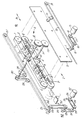
- An example of article transport apparatus according to the invention will now be described with reference to the accompanying drawing which is a schematic, exploded view of the apparatus.
- The apparatus comprises a support housing including main side plates 1 (part of one of which is shown in the drawing), the support housing supporting a carriage 2 by means not shown such that the carriage can move to and fro between the main side plates 1 in the directions A. The carriage comprises a pair of side plates 3 (one of which is shown in the drawing) suspended between the main side plates 1 with a
sheet conveying system 4 mounted between the side plates 3. - The
sheet conveying system 4 comprises a pair of belts 5, 6 entrained aroundidler rollers 7, 8 respectively and drive rollers 9, 10. The belts 5, 6 define a sheet feed path 11 with adjacent surfaces of the belts being urged together via theidler rollers 8 which are spring biased by means not shown towards the idler rollers 7. - The drive roller 10 is non-rotatably mounted to a shaft 11 carrying a
drive gear 12, the shaft 11 being rotatably mounted between the carriage side plates 3. Asecond shaft 13 is also rotatably mounted between the carriage side plates 3 and carries non-rotatably agear 14 which is meshed with thegear 12 and the drive roller 9. - A first drive system is provided for causing the to and fro movement of the carriage 2. This first drive system comprises a
drive motor 15 coupled viapulleys 16 and a toothed drive belt 17 to apulley 18 rotatably mounted to a side plate 1. Atoothed drive belt 20 is entrained around thepulley 18 and anotherpulley 19 also mounted to the side plate 1 and carries abracket 21 which is coupled with one of the carriage side plates 3 through a slot in the main side plate 1 (not shown). - Movement of the
sheet conveying system 4 is controlled by a second drive system including adrive motor 22 coupled viapulleys 23 andbelts 24 to adrive pulley 25 rotatably mounted to the side plate 1 opposite to that to which the first drive system is connected. A toothed belt 26 is entrained around thedrive pulley 25 and around an idler wheel 27 rotatably mounted to the same side plate 1 as thedrive wheel 25. In addition, the toothed drive belt 26 is entrained aroundpulleys pulley 30 non-rotatably mounted to theshaft 13. The pitch circle diameter of thepulley 30 is the same of that of the pulley 9. - If the
motor 15 is held stationary, actuation of themotor 22 in the direction of the arrow 31 will cause movement of the belts 5, 6 such that a sheet held at the point P between the belts will move to the right, as seen in the drawings. - With the
motor 22 stopped and themotor 15 actuated, the carriage 2 will be moved to the right or to the left depending on the direction of rotation of themotor 15. - In operation, a previously formed stack of sheets is held stationary at a position 32 by means not shown. The stack of sheets may have been generated in any conventional manner but in the preferred apparatus has been generated by a system similar to that described in our copending European patent application claiming priority from British Patent Application No.8904566.0 or GB-A-2193712. With the
motor 22 held stationary and hence thepulley 25 stationary, themotor 15 is actuated to cause the carriage 2 to move to the left as seen in the drawing. This movement will cause the pulleys 28 - 30 mounted to the carriage to move to the left and hence rotate since the belt 26 is stationary. This will cause theshaft 13 to rotate and hence the belts 5, 6 will undergo a caterpillar track action such that both portions of the belts defining the feed path 11 will remain stationary and effectively the belts 5, 6 self-feed onto the stack 32. Since there is no relative, linear movement between the stack 32 and the belts 5, 6 the problem of scuffing will not occur. - Once the stack 32 is firmly gripped between the belts 5, 6 there is a choice of action which the apparatus can perform to deliver the stack. In one case, it may be designed to move the stack to the left, as seen in the drawing, to a
dispense position 40 in which case themotor 15 is further actuated to cause the carriage 3 to move beyond the initial position of the stack 32 following which themotor 15 is stopped and themotor 22 actuated so that the belts 5, 6 are rotated to feed the stack to thedispense position 40. - In another case, once the stack 32 is firmly gripped between the belts 5, 6 it can be wound towards the right as seen in the drawing by rotation of the
motor 22. The carriage 2 can now be advanced to the right by rotatingmotor 15 and thereafter themotor 22 can be rotated to feed the stack to the right to a dispense position 41. The stack of notes remains stationary whenmotor 15 rotates. The stack of notes and the carriage can only move in unison if the two motors are driven in unison, other progress has to be made in a series of steps related to the transport length of the carriage.
Claims (5)
Applications Claiming Priority (2)
| Application Number | Priority Date | Filing Date | Title |
|---|---|---|---|
| GB898904569A GB8904569D0 (en) | 1989-02-28 | 1989-02-28 | Article handling apparatus |
| GB8904569 | 1989-02-28 |
Publications (2)
| Publication Number | Publication Date |
|---|---|
| EP0385652A1 true EP0385652A1 (en) | 1990-09-05 |
| EP0385652B1 EP0385652B1 (en) | 1993-12-15 |
Family
ID=10652469
Family Applications (1)
| Application Number | Title | Priority Date | Filing Date |
|---|---|---|---|
| EP90301874A Expired - Lifetime EP0385652B1 (en) | 1989-02-28 | 1990-02-21 | Article handling apparatus |
Country Status (5)
| Country | Link |
|---|---|
| US (1) | US5060930A (en) |
| EP (1) | EP0385652B1 (en) |
| JP (1) | JPH02267684A (en) |
| DE (1) | DE69005153T2 (en) |
| GB (1) | GB8904569D0 (en) |
Cited By (4)
| Publication number | Priority date | Publication date | Assignee | Title |
|---|---|---|---|---|
| US5267729A (en) * | 1990-08-31 | 1993-12-07 | Konica Corporation | Sorter having a belt guide with a cushion member |
| EP0749915A1 (en) * | 1995-06-20 | 1996-12-27 | Carl Schenck Ag | Telescopic transporting device |
| EP1172311A2 (en) * | 2000-07-14 | 2002-01-16 | viastore systems GmbH | Supporting device |
| US20110217407A1 (en) * | 2010-03-03 | 2011-09-08 | Ken Haines | Material sheet guiding system for a thermoforming machine |
Families Citing this family (4)
| Publication number | Priority date | Publication date | Assignee | Title |
|---|---|---|---|---|
| US5961114A (en) * | 1997-11-21 | 1999-10-05 | Pitney Bowes Inc. | Mailpiece stacking structure |
| DE19840420A1 (en) * | 1998-09-04 | 2000-03-09 | Giesecke & Devrient Gmbh | Device for transporting sheet-like conveyed goods |
| JP5491202B2 (en) | 2007-02-19 | 2014-05-14 | スリーエム イノベイティブ プロパティズ カンパニー | Apparatus and method for supplying vehicle stabilization weight |
| JP5899107B2 (en) * | 2012-12-17 | 2016-04-06 | 日立オムロンターミナルソリューションズ株式会社 | Automated teller machine |
Citations (5)
| Publication number | Priority date | Publication date | Assignee | Title |
|---|---|---|---|---|
| DE307385C (en) * | ||||
| DE2509519A1 (en) * | 1975-03-05 | 1976-09-09 | Womako Masch Konstr | Conveyor speed control for bookbinding machine - includes roller system with associated horizontally adjustable pulleys |
| FR2310210A1 (en) * | 1975-05-06 | 1976-12-03 | Lagain Georges | DEVICE FOR RECEIVING AND TRANSPORTING FLAT OBJECTS, IN PARTICULAR AT THE EXIT OF A MACHINE FOR MAKING BAGS |
| US4580774A (en) * | 1982-11-02 | 1986-04-08 | Fuji Photo Film Co., Ltd. | Sheet material accumulating device |
| GB2198122A (en) * | 1986-12-01 | 1988-06-08 | De La Rue Syst | Sheet store loading apparatus |
Family Cites Families (6)
| Publication number | Priority date | Publication date | Assignee | Title |
|---|---|---|---|---|
| GB1130582A (en) * | 1965-05-26 | 1968-10-16 | Broadbent & Sons Ltd Thomas | Improvements in or relating to stacking devices |
| GB1516303A (en) * | 1974-07-19 | 1978-07-05 | Metal Box Co Ltd | Conveyor apparatus |
| US4185815A (en) * | 1978-03-17 | 1980-01-29 | International Business Machines Corporation | Sheet feed |
| GB2066761B (en) * | 1978-11-01 | 1983-04-07 | Molins Ltd | Handling rod-like articles |
| JPS58211750A (en) * | 1982-06-03 | 1983-12-09 | Olympus Optical Co Ltd | Original driver of copying machine |
| US4715774A (en) * | 1985-12-23 | 1987-12-29 | Peddinghaus Corporation | Workpiece advancing apparatus |
-
1989
- 1989-02-28 GB GB898904569A patent/GB8904569D0/en active Pending
-
1990
- 1990-02-21 EP EP90301874A patent/EP0385652B1/en not_active Expired - Lifetime
- 1990-02-21 DE DE90301874T patent/DE69005153T2/en not_active Expired - Fee Related
- 1990-02-27 JP JP2044657A patent/JPH02267684A/en active Pending
- 1990-02-27 US US07/485,444 patent/US5060930A/en not_active Expired - Fee Related
Patent Citations (5)
| Publication number | Priority date | Publication date | Assignee | Title |
|---|---|---|---|---|
| DE307385C (en) * | ||||
| DE2509519A1 (en) * | 1975-03-05 | 1976-09-09 | Womako Masch Konstr | Conveyor speed control for bookbinding machine - includes roller system with associated horizontally adjustable pulleys |
| FR2310210A1 (en) * | 1975-05-06 | 1976-12-03 | Lagain Georges | DEVICE FOR RECEIVING AND TRANSPORTING FLAT OBJECTS, IN PARTICULAR AT THE EXIT OF A MACHINE FOR MAKING BAGS |
| US4580774A (en) * | 1982-11-02 | 1986-04-08 | Fuji Photo Film Co., Ltd. | Sheet material accumulating device |
| GB2198122A (en) * | 1986-12-01 | 1988-06-08 | De La Rue Syst | Sheet store loading apparatus |
Cited By (5)
| Publication number | Priority date | Publication date | Assignee | Title |
|---|---|---|---|---|
| US5267729A (en) * | 1990-08-31 | 1993-12-07 | Konica Corporation | Sorter having a belt guide with a cushion member |
| EP0749915A1 (en) * | 1995-06-20 | 1996-12-27 | Carl Schenck Ag | Telescopic transporting device |
| EP1172311A2 (en) * | 2000-07-14 | 2002-01-16 | viastore systems GmbH | Supporting device |
| EP1172311A3 (en) * | 2000-07-14 | 2003-06-04 | viastore systems GmbH | Supporting device |
| US20110217407A1 (en) * | 2010-03-03 | 2011-09-08 | Ken Haines | Material sheet guiding system for a thermoforming machine |
Also Published As
| Publication number | Publication date |
|---|---|
| GB8904569D0 (en) | 1989-04-12 |
| US5060930A (en) | 1991-10-29 |
| DE69005153D1 (en) | 1994-01-27 |
| EP0385652B1 (en) | 1993-12-15 |
| DE69005153T2 (en) | 1994-04-28 |
| JPH02267684A (en) | 1990-11-01 |
Similar Documents
| Publication | Publication Date | Title |
|---|---|---|
| US4158456A (en) | Device for separating documents, cards and the like, especially paper money bills | |
| EP0056946B2 (en) | An arrangement for the feeding of objects | |
| US3593624A (en) | Automatic stacking machine | |
| EP0003372A1 (en) | Improved feed mechanism for sequentially separating documents, sheets, coupons and the like | |
| EP0369760B1 (en) | Document feed mechanism incorporating an idler wheel assembly | |
| US7168696B2 (en) | Apparatus and method for separating flat parceled goods | |
| US5060930A (en) | Apparatus for receiving articles by self-feeding and for conveying and dispensing such articles | |
| JP2636252B2 (en) | Document distribution machine | |
| JP3286203B2 (en) | Cut-out conveyor device for flat box-shaped articles | |
| EP0773901B1 (en) | High capacity stacker/separating device | |
| US5409207A (en) | Stacking of flexible planar articles | |
| JPH09188437A (en) | Device for taking out printed product which is conveyed at regular intervals astride saddle-shaped loading part of conveyance device by serially-traveling member circulating | |
| US5823738A (en) | Method and unit for forming stacks of articles | |
| JP3478507B2 (en) | Shredder paper feeder | |
| JP3032581B2 (en) | Reversing device | |
| JP2000506108A (en) | A device that changes the transport direction of individual sheets | |
| US3994389A (en) | Mail stack feed control | |
| JPH08282837A (en) | Sorting device | |
| JPS636110Y2 (en) | ||
| JPH0336155A (en) | Ticket storing device | |
| US4708335A (en) | Sheet presenting assembly | |
| JP2564553B2 (en) | Paper stacker mechanism | |
| JPS63196448A (en) | Sorter | |
| JPH0330325Y2 (en) | ||
| JPH089809Y2 (en) | Transporting mechanism of direction changing part in coin processing machine |
Legal Events
| Date | Code | Title | Description |
|---|---|---|---|
| PUAI | Public reference made under article 153(3) epc to a published international application that has entered the european phase |
Free format text: ORIGINAL CODE: 0009012 |
|
| AK | Designated contracting states |
Kind code of ref document: A1 Designated state(s): CH DE ES FR GB LI SE |
|
| 17P | Request for examination filed |
Effective date: 19901207 |
|
| 17Q | First examination report despatched |
Effective date: 19920623 |
|
| RAP1 | Party data changed (applicant data changed or rights of an application transferred) |
Owner name: DE LA RUE SYSTEMS LIMITED |
|
| GRAA | (expected) grant |
Free format text: ORIGINAL CODE: 0009210 |
|
| AK | Designated contracting states |
Kind code of ref document: B1 Designated state(s): CH DE ES FR GB LI SE |
|
| PG25 | Lapsed in a contracting state [announced via postgrant information from national office to epo] |
Ref country code: SE Effective date: 19931215 Ref country code: LI Effective date: 19931215 Ref country code: ES Free format text: THE PATENT HAS BEEN ANNULLED BY A DECISION OF A NATIONAL AUTHORITY Effective date: 19931215 Ref country code: CH Effective date: 19931215 |
|
| REF | Corresponds to: |
Ref document number: 69005153 Country of ref document: DE Date of ref document: 19940127 |
|
| REG | Reference to a national code |
Ref country code: CH Ref legal event code: PL |
|
| ET | Fr: translation filed | ||
| PLBE | No opposition filed within time limit |
Free format text: ORIGINAL CODE: 0009261 |
|
| STAA | Information on the status of an ep patent application or granted ep patent |
Free format text: STATUS: NO OPPOSITION FILED WITHIN TIME LIMIT |
|
| 26N | No opposition filed | ||
| PGFP | Annual fee paid to national office [announced via postgrant information from national office to epo] |
Ref country code: FR Payment date: 19980210 Year of fee payment: 9 |
|
| PGFP | Annual fee paid to national office [announced via postgrant information from national office to epo] |
Ref country code: GB Payment date: 19980212 Year of fee payment: 9 |
|
| PGFP | Annual fee paid to national office [announced via postgrant information from national office to epo] |
Ref country code: DE Payment date: 19980302 Year of fee payment: 9 |
|
| REG | Reference to a national code |
Ref country code: GB Ref legal event code: 732E |
|
| PG25 | Lapsed in a contracting state [announced via postgrant information from national office to epo] |
Ref country code: GB Free format text: LAPSE BECAUSE OF NON-PAYMENT OF DUE FEES Effective date: 19990221 |
|
| REG | Reference to a national code |
Ref country code: FR Ref legal event code: TP Ref country code: FR Ref legal event code: CA |
|
| GBPC | Gb: european patent ceased through non-payment of renewal fee |
Effective date: 19990221 |
|
| PG25 | Lapsed in a contracting state [announced via postgrant information from national office to epo] |
Ref country code: FR Free format text: LAPSE BECAUSE OF NON-PAYMENT OF DUE FEES Effective date: 19991029 |
|
| PG25 | Lapsed in a contracting state [announced via postgrant information from national office to epo] |
Ref country code: DE Free format text: LAPSE BECAUSE OF NON-PAYMENT OF DUE FEES Effective date: 19991201 |
|
| REG | Reference to a national code |
Ref country code: FR Ref legal event code: ST |