EP0385607B1 - Modular shelving and hanger bar system - Google Patents
Modular shelving and hanger bar system Download PDFInfo
- Publication number
- EP0385607B1 EP0385607B1 EP90301556A EP90301556A EP0385607B1 EP 0385607 B1 EP0385607 B1 EP 0385607B1 EP 90301556 A EP90301556 A EP 90301556A EP 90301556 A EP90301556 A EP 90301556A EP 0385607 B1 EP0385607 B1 EP 0385607B1
- Authority
- EP
- European Patent Office
- Prior art keywords
- shelf
- plank
- bracket
- hanger bar
- boss
- Prior art date
- Legal status (The legal status is an assumption and is not a legal conclusion. Google has not performed a legal analysis and makes no representation as to the accuracy of the status listed.)
- Expired - Lifetime
Links
Images


Classifications
-
- A—HUMAN NECESSITIES
- A47—FURNITURE; DOMESTIC ARTICLES OR APPLIANCES; COFFEE MILLS; SPICE MILLS; SUCTION CLEANERS IN GENERAL
- A47B—TABLES; DESKS; OFFICE FURNITURE; CABINETS; DRAWERS; GENERAL DETAILS OF FURNITURE
- A47B96/00—Details of cabinets, racks or shelf units not covered by a single one of groups A47B43/00 - A47B95/00; General details of furniture
Definitions
- This invention relates to a modular shelving and hanger bar system adapted for easy installation in varied configurations in clothes closets of various sizes.
- Some prior art systems have proposed creating shelf planks from smaller shelf segments, two inches wide for example.
- One such system contemplates an inter-plan linking mechanism on each plank segment allowing the required number of segments to be coupled together to form a shelf.
- attachment of the completed plank to a horizontal support bracket occurs only between the front and back plank segments and the horizontal support.
- the interior plank segments only rest against the horizontal support bracket and are susceptible to disturbance from beneath the segments.
- Another plank segment system requires a variety of cross members spanning between corresponding horizontal support brackets. These brackets must be attached to the support brackets by nuts and bolts and anchoring hardware.
- the present invention is characterized by the features of the characterizing portion of claim 1.
- One embodiment of this invention provides a modular shelf assembly for installation into a closet, for example.
- the assembly comprises a pair of horizontal shelf brackets, each bracket having a plurality of plank securing members along its upper face.
- a plurality of shelf planks each shelf plank having a transverse cross section complementary to a plank securing member, elastically engage the shelf brackets, namely a generally trapezoidal, U-shaped cross-section.
- At least one vertical support member a means for attaching one end of the horizontal shelf bracket to the vertical support member and a means for attaching the other end of the horizontal shelf bracket to a wall.
- a configuration of horizontal shelf brackets, shelf planks, and vertical support members is adapted to fit in a storage space, such as a closet, for example.
- a storage space such as a closet
- Each of several horizontal shelf brackets is attached at one end of the bracket to a back wall and at the other end of the bracket to a vertical support member extending upwardly from the floor of the closet.
- Each end of a shelf plank is manually snapped onto a plank securing member of the shelf support bracket.
- the shelf plank elastically engages the plank securing member to form a tight frictional fit requiring no other attachment device or fastener for securing the plank.
- the number of shelf planks required for the desired shelf depth are similarly attached to the plank securing members, thereby enabling quick and easy assembly of the shelf.
- the shelf planks are made to nest easily for packaging.
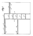
- FIG. 1 is a front view of one exemplary configuration of a modular shelving and hanger bar system for installation in a clothes closet, for example.
- the system can be installed in spaces of varying width and height and many shelf configurations are possible.
- a pair of vertical support members 4 support a plurality of horizontal support members (not visible in FIG. 1) extending from each vertical support member to the back wall of a typical closet.
- the various components of the system are individually described hereinafter.
- a plurality of shelf planks 5 extend between corresponding horizontal support members to create a center stack of shelves. Somewhat longer shelf planks extend from each side of the center stack to the respective side walls of a typical closet.
- a stiffening bridge 12 enhances the sturdiness of the longer shelf members.
- Support of the longer shelf planks at the sidewall is provided by a sidewall shelf and hanger bar bracket 8.
- the sidewall bracket also supports one end of a hanger bar 10 provided below each set of shelves extending to the sidewalls.
- a sidewall hanger bar bracket 27 provides an alternative sidewall support for a hanger bar. The other end of each hanger bar is supported by a socket integral with the corresponding horizontal support bracket.
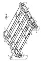
- FIG. 2 shows the construction of a single shelf from the center stack of the system.
- a pair of elongated central shelf brackets 1 are each anchored at the back end to the back wall of the closet by a back wall mounted bracket or stud 15 (FIG. 10) which engages a cleat 17 on the back end of each central bracket.
- the front end of each central bracket has a screw hole 3 and fastens to a vertical support member 4 which stands on the floor and extends toward the ceiling, but which need not be fastened to the floor or ceiling.
- the central shelf bracket and vertical support member combination provide the support for a plurality of shelf planks 5 which engage trapezoidal bosses 6 along the top of the central bracket 1.
- Protective, decorative plank end caps 30 engage and cover the end of each plank.
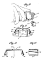
- FIG. 3 is an isometric view from below the upper shelf of FIG. 1.
- a sidewall shelf and hanger bar bracket 8 is mounted to a side wall using mounting screws through mounting holes 9 in the web of the shelf and hanger bar bracket.
- the sidewall bracket provides support for one end of a plurality of shelf planks 5 and for one end of the hanger bar 10 on which clothes may be hung by hangers, for example.
- the back end of a central shelf and hanger bar bracket 11 is anchored to a back wall mounted stud 15 (FIG. 10) by means of a cleat 17 integral with the back edge of the bracket 11, which engages the wall stud.
- the front end of the bracket contains at least one screw hole 3 by which the bracket is fastened to a vertical support member with at least one screw.
- the central shelf and hanger bar bracket 11 provides support for the other end of the hanger bar 10 and is a support between the ends of shelf planks 5 which extend to a sidewall (not shown) where the plank ends are supported by a sidewall shelf bracket (hereinafter described).
- the central shelf and hanger bracket supports one end of a plurality of shelf planks extending to a sidewall shelf bracket.
- an elongated stiffening bridge 12 may be employed.
- FIG. 6 presents a side view of such a stiffening bridge.
- the stiffening bridge is of I-beam like cross-section and constructed of plastic such as polypropylene. Trapezoidal bosses 6, each with a shape complementary to a shelf plank, are spaced along the top flange of each bracket at intervals the same as the boss spacing of the central shelf bracket 1 (FIG. 2) and its variations.
- the stiffening bridge may be inserted into the bottom of a plurality of shelf planks, as shown in FIG. 3 to provide stiffening and stabilization of the shelf planks where there is a relatively long shelf span, about a meter, for example.
- the bridge distributes the load between the planks, and minimizes deflections of individual planks in the event the load is unevenly distributed.
- each vertical support member 4 comprises at least two interconnected shorter members.
- each shorter member is formed from metal, preferably lightweight, roll-formed steel and has a length of a little over a meter, for example, with a hollow, somewhat oval, broad base, C-shaped cross-section as shown in FIG. 8.
- the flat back portion of the support member has labeled screw holes at intervals along the length of the member. The labeled holes are used both as a template for marking the back wall of the closet for hole drilling and as a means for attaching various shelf brackets.
- the shorter members are interconnected to form the vertical support member by means of a joiner insert 13, one embodiment of which is indicated in FIG. 9.
- the insert can be formed from hard plastic, preferably glass reinforced polypropylene.
- the insert is approximately ten centimeters in length and has a generally oval, broad base cross-section, conforming to the interior cross-section of the vertical support member.
- a narrow raised rib 14 extends around the circumference of the insert at a point midway between the ends of the insert. Both ends of the insert are hollow and are tapered to facilitate introduction of the insert into an end of the shorter members.
- the insert is introduced into one end of the shorter member such that the raised rib 14 abuts against the end of the shorter member and acts as a stop.
- the remaining exposed end of the insert is inserted into the end of a second shorter member, thereby forming the vertical support member 4.
- Shorter members of any length may be used and any number of them may be connected to comprise the vertical support member.
- the holes in the vertical support member serve as a template for marking the back wall of a closet for hole drilling.
- the wall holes are required to mount the wall studs 15 shown in FIG. 10, which provide support for the back end of the central shelf brackets 1 and the central shelf and hanger bar brackets 11 (FIG. 3).
- the back wall bracket or stud is a generally rectangular solid having a broadened T-shaped pocket 16 extending down from the top of the stud.
- the front face of the pocket (the leg of the T) is open from the top.
- the pocket receives a broadened T-shaped cleat 17 at the back end of a shelf support bracket.
- the stud has a hole through the back of the T-shaped pocket (hidden in FIG. 10) for receiving a mounting screw.
- the stud is attached to the wall using any standard screw and wall anchor arrangement.
- the T-shaped cleat 17 is integral with one end of the central shelf bracket.
- the cleat transverse cross-section corresponds to the cross-section of the T-shaped pocket of the wall stud.
- the top of the cleat is terminated by an extension 18 of the bracket, the extension protruding beyond the edge of the bracket a distance approximately equal to the cross-sectional dimension of the wall stud.
- the exposed end of the cleat is inserted into the pocket of the wall stud and slidably engages the stud.
- the cleat is inserted to the point where the lower face of the solid extension 18 abuts the upper face of the wall stud, the extension thereby acting as a stop.
- the rear face of the bracket abuts the opposing wall stud face.
- each central shelf bracket integral with the central shelf bracket, at the end opposite from the rear cleat 17, is a screw boss 32 having a bore 19 with a longitudinal axis parallel to the longitudinal axis of the bracket, for receiving a mounting screw.
- the front end of the bracket is attached to the vertical support member by a screw through a hole in the flat portion of the vertical support member into a bore 19 in the front end of the bracket.
- the central shelf bracket also has a symmetrical I-beam type cross-section (viewed in side view in FIG. 4 and in perspective in FIG. 10) and is constructed of plastic such as polypropylene.
- the top and bottom flanges of each bracket are two centimeters wide, for example, and the overall height is about five centimeters. For a typical closet, the length of a bracket is about 32 centimeters.
- FIG. 11 presents an enlarged side view of such a boss. It is preferable that each boss be so shaped as to allow for an outwardly opposed camming motion of the shelf plank legs, as will be later described.
- Each boss has a flattened, trapezoidal shape with rounded upper corners 22 and a channel 20 at each side of its base for receiving inwardly directed lips 21 of a shelf plank 5. In other words, the bosses protrude into the notches between bosses a small amount above each channel to provide a place for elastically connecting the planks onto the brackets.
- a pair of slightly raised ribs 35 extend across the top of the boss transverse to the length of the bracket (illustrated only in Fig 11).
- Each shelf plank has a flattened trapezoidal U-shaped cross-section with an inwardly directed lip 21 at the end of each leg 23 of the U.
- the descending and diverging legs form the front and rear faces of the plank.
- Each lip has a double thickness with a lower inwardly directed portion and an upper outwardly directed portion above it. This provides a smooth folded edge along the inward edge of the lip.
- the rough or sharp cut edge of the steel strip that forms the shelf plank is safely folded inside.
- the distance between the edges of the lips along each edge of the plank is more than the width of the top face of the plank so that a plurality of planks can be nested for packaging and shipment.
- the shelf plank may be constructed of any metal, preferably lightweight, roll formed, prepainted steel, which has resilient properties allowing for transverse elastic deformation.
- the shelf planks may be of differing lengths as desired for making a particular assembly of shelves to fit a closet.
- Each shelf plank is attached to a boss by placing the plank in a straddling position over the boss, with one plank leg 23 over each side of the boss, and applying a steady downward pressure. Initially, each inwardly directed lip 21 of the shelf plank abuts a diagonally canted face 33 of the trapezoidal boss. As pressure is applied to the top of the shelf plank, the plank legs are cammed outwardly by the interaction between the shelf plank lips and the diagonal faces of the boss. When each lip travels past the lower edge of the boss, the elasticity of the plank leg causes the lip to be snapped into the boss channel 20, thereby removably locking the shelf plank to the boss.
- the raised ribs on top of the boss slightly bend the top face of the plank (shown exaggerated in FIG. 11), further drawing the legs of the U-shaped plank toward the sides of the boss and tightening the lips into the channels.
- the ridges assure tight engagement of the planks with the brackets, stiffening and rigidifying the shelving system.
- the planks remain elastically bent a small amount when engaged with the bosses to fit tightly.
- the top of the boss could be slightly rounded or have a raised central area, or the planks could have a slight reverse curvature on their top faces to provide such elastic tightening.
- FIG. 3 a central shelf and hanger bar bracket 11 is shown.
- the bracket similar in basic shape and properties to the central shelf bracket 1, incorporates a socket 24 for receiving one end of the hanger bar.
- the socket is positioned below one end of the bracket, but the socket may be positioned at any point along the horizontal length of the bracket if, for example, a wider shelf were desired.
- FIG. 5 An end view of such a socket into which a hanger bar 10 has been inserted is seen in FIG. 5.
- the socket has a cross-section to accept one end of a hanger bar and is here shown as oval. Integral with one flat surface of the socket interior is a slight protrusion 25 which engages one of the flat sides of the oval hanger bar, transversely compressing the hanger bar and providing a tight frictional engagement between the socket and the hanger bar end.
- the hanger bar may be constructed of metal, preferably resilient roll formed pre-painted steel, and as embodied here has a hollow oval cross-section with a discontinuity 26 in one rounded end.
- the opposing edges which are adjacent to each other at the discontinuity are safely rolled inward.
- the hanger bar socket shown in FIG. 5 is integral with the illustrated sidewall shelf and hanger bar bracket 8.
- the sidewall bracket is of similar construction to the central bracket but is supported by a sidewall of a closet, and thus, screw holes 9 pass through the web of the sidewall bracket 8 to allow attachment to a wall.
- FIG. 7 presents an elevation view of a sidewall hanger bar bracket 27 having two screw holes 34, and a socket, similar to that described in the preceding text, for receiving an end of a hanger bar.
- One screw hole passes through the rear face of the socket.
- the sidewall hanger bar bracket is used to support one end of a hanger bar, the other end of which may be supported at the central stack of shelves or the opposite wall.
- Cover strips 29 of a cross-section as shown in FIG. 8 may be attached to the vertical support members for cosmetic purposes.
- Each cover strip is preferably formed from resiliently deformable plastic and is of a hollow oval C-shaped cross-section complementary in interior dimension to the cross-section of the vertical support member and of a length equal to that of a shorter support member.
- Each cover strip is attached to the front face of a support member by pressing the legs of the strip against the opposing curved ends of the support member. The legs cam opposingly outward and then spring inward as they pass the widest transverse dimension of the support member.
- the resiliency of the cover strip allows a tight frictional engagement between the cover strip and the vertical support member. The cover strip thus hides the open front of the vertical support member and the screw heads which are inside the vertical support member.
- a plastic plank end cap 30 may be employed to cover the sheared end of a shelf plank.
- the plank end cap is of generally flattened, trapezoidal U-shaped cross-section, complementary to the cross-section of the shelf plank, and has an inwardly directed lip 31 at the end of each leg of the U.
- a molded rim 32 is integral with one cross-sectional edge and covers and abuts the edge of the junction between the plank end and the shelf bracket boss.
- the user In using the modular shelving and hanger bar system, the user initially decides on an overall shelf and/or hanger bar configuration. Many configurations are possible and can vary in complexity and size from a simple shelf, comprising shelf planks and sidewall shelf brackets and requiring no vertical support member, to a more elaborate combination of brackets, shelf planks and vertical supports such as shown in FIG. 1.
- Examples of such systems would include: a tower shelf arrangement using at least two vertical support members and at least two central shelf brackets extending from a back wall to the vertical support members and supporting a plurality of shelf planks; a sidewall shelf arrangement having shelf planks supported at one end by a sidewall shelf bracket and at the other end by a central shelf bracket extended between a back wall and a vertical support member; and, at least one hanger bar supported at each end by a sidewall hanger bar bracket mounted between a vertical support member and a rear wall or supported at one end by a side wall hanger bar bracket.
- These assemblies are merely illustrative of some of the basic configurations possible and are not meant as a comprehensive listing.
- the configuration is to include vertical support members, these members are assembled to the desired height using the required number of shorter support members in conjunction with joiner inserts.
- the holes in the assembled vertical support member serve to locate the mounting positions for any required wall studs.
- the vertical support member is placed in an upright position against the wall and marks are applied to the wall through the screw holes at those heights where wall studs and shelf brackets are to be located. Holes are then drilled into the wall at the marked locations, and screw inserts introduced into the holes.
- a wall stud is then attached to the wall insert with a screw.
- the wall stud is oriented such that the T-shape pocket opens in an upward direction.
- the T-shaped cleat at one end of the shelf bracket is inserted into the opening of the wall stud pocket and depressed to the point that the bottom of the shelf bracket extension abuts the top face of the wall stud.
- the desired number of shelf brackets are so installed.
- the front end of each mounted shelf bracket is then attached to the vertical support member using mounting screws.
- Shelf planks are precut to a length equal to the distance between the outer edge of a shelf bracket of one vertical arrangement and the outer edge of the corresponding shelf bracket in the second vertical arrangement. Each end of each central tower shelf plank is then snapped into place on a boss of a shelf bracket. Plank end caps may then be snapped on to each exposed junction between plank end and shelf bracket boss for aesthetic and protective purposes. Similarly, cover strips may be applied over the forward facing openings of the vertical support members and caps applied to the tops. Custom-sized shelf planks may be similarly erected between a side wall shelf bracket and one or both of the central shelf brackets. A central shelf and hanger bar bracket may be used in place of a central shelf bracket at selected locations to enable installation of a hanger bar. Again, many configurations are possible.
- planks may have longitudinal corrugations which are largely a matter of changing the appearance, although some stiffening may also result.
- planks might be provided with an inverted trapezoidal cross section to fit into notches between bosses. These could be used in lieu of the planks hereinabove described and illustrated, or could, with only minor modifications, be interspersed between the illustrated planks to make a shelf that is essentially continuous instead of being formed of spaced apart planks. If desired, the illustrated planks may be placed closer together to make a stiffer, more nearly continuous upper surface on the shelf. Other shapes of generally U-shaped planks may also be suitable.
- a vertical support member end cap having a screw hole for attachment to a floor or ceiling, may be used. Such an end cap would receive and anchor an end of the support member, prohibiting lateral motion.
Description
- This invention relates to a modular shelving and hanger bar system adapted for easy installation in varied configurations in clothes closets of various sizes.
- It often provides economy of storage space to install shelves into closets under construction as well as into existing closets in the home. It is desirable to provide a versatile modular shelving and hanger bar system which could be configured in a variety of ways and installed in closets of varying sizes. It is also desirable that the components of the system be of lightweight yet strong materials, and that the assembled system have a solid, stable appearance as well as actually being rigid.
- Some prior art shelving systems for the home after market are constructed of welded, coated wire, and although lightweight, do not present a sturdy appearance. Further, items smaller than the gaps between wire supports may not be stored with this type system.
- Other prior art shelving systems are of wood, particle board, or sheet metal construction. These types of systems usually comprise shelves and vertical supports of single plank construction and require the retailer to stock a large variety of plank sizes to allow for versatility of configuration. Further, when packed for retail sale, these systems comprise large, heavy and unwieldy packages.
- Some prior art systems have proposed creating shelf planks from smaller shelf segments, two inches wide for example. One such system contemplates an inter-plan linking mechanism on each plank segment allowing the required number of segments to be coupled together to form a shelf. However, attachment of the completed plank to a horizontal support bracket occurs only between the front and back plank segments and the horizontal support. The interior plank segments only rest against the horizontal support bracket and are susceptible to disturbance from beneath the segments. Another plank segment system requires a variety of cross members spanning between corresponding horizontal support brackets. These brackets must be attached to the support brackets by nuts and bolts and anchoring hardware.
- A prior art system according to the preamble of claim 1 is disclosed in US-A-2,834,478.
- The present invention is characterized by the features of the characterizing portion of claim 1.
- One embodiment of this invention provides a modular shelf assembly for installation into a closet, for example. The assembly comprises a pair of horizontal shelf brackets, each bracket having a plurality of plank securing members along its upper face. A plurality of shelf planks, each shelf plank having a transverse cross section complementary to a plank securing member, elastically engage the shelf brackets, namely a generally trapezoidal, U-shaped cross-section.
- Supplemental to the above embodiment is at least one vertical support member, a means for attaching one end of the horizontal shelf bracket to the vertical support member and a means for attaching the other end of the horizontal shelf bracket to a wall.
- In the assembly of the above exemplary embodiment, a configuration of horizontal shelf brackets, shelf planks, and vertical support members is adapted to fit in a storage space, such as a closet, for example. Each of several horizontal shelf brackets is attached at one end of the bracket to a back wall and at the other end of the bracket to a vertical support member extending upwardly from the floor of the closet.
- Each end of a shelf plank is manually snapped onto a plank securing member of the shelf support bracket. The shelf plank elastically engages the plank securing member to form a tight frictional fit requiring no other attachment device or fastener for securing the plank. The number of shelf planks required for the desired shelf depth are similarly attached to the plank securing members, thereby enabling quick and easy assembly of the shelf. The shelf planks are made to nest easily for packaging.
- These and other aspects of the invention will be more fully understood by referring to the following detailed description and the accompanying drawings wherein:
- FIG. 1 is a front view of an exemplary configuration of a modular shelving and hanger bar system;
- FIG. 2 is an isometric view of one shelf;
- FIG. 3 is an isometric view from below another shelf;
- FIG. 4 is a side view of a central shelf bracket with plank end cap;
- FIG. 5 is a side view of a sidewall shelf and hanger bar bracket;
- FIG. 6 is a side view of a stiffening bridge;
- FIG. 7 is a front view of a sidewall hanger bar bracket;
- FIG. 8 is a cross-sectional view of a vertical support member and cover strip;
- FIG. 9 is an isometric view of a joiner insert for the vertical support members;
- FIG. 10 illustrates the coupling of a central shelf bracket and a back wall bracket or stud;
- FIG. 11 is a fragmentary side view of a sidewall shelf and hanger bar bracket boss and end of a shelf plank;
- FIG. 12 is a side view of a plank end cap; and
- FIG. 13 is a side view taken on line 13-13 of FIG. 12.
- FIG. 1 is a front view of one exemplary configuration of a modular shelving and hanger bar system for installation in a clothes closet, for example. The system can be installed in spaces of varying width and height and many shelf configurations are possible. In this example a pair of
vertical support members 4 support a plurality of horizontal support members (not visible in FIG. 1) extending from each vertical support member to the back wall of a typical closet. The various components of the system are individually described hereinafter. - A plurality of
shelf planks 5 extend between corresponding horizontal support members to create a center stack of shelves. Somewhat longer shelf planks extend from each side of the center stack to the respective side walls of a typical closet. Astiffening bridge 12 enhances the sturdiness of the longer shelf members. Support of the longer shelf planks at the sidewall is provided by a sidewall shelf andhanger bar bracket 8. The sidewall bracket also supports one end of ahanger bar 10 provided below each set of shelves extending to the sidewalls. A sidewallhanger bar bracket 27 provides an alternative sidewall support for a hanger bar. The other end of each hanger bar is supported by a socket integral with the corresponding horizontal support bracket. - FIG. 2 shows the construction of a single shelf from the center stack of the system. In this embodiment, a pair of elongated central shelf brackets 1 are each anchored at the back end to the back wall of the closet by a back wall mounted bracket or stud 15 (FIG. 10) which engages a
cleat 17 on the back end of each central bracket. The front end of each central bracket has ascrew hole 3 and fastens to avertical support member 4 which stands on the floor and extends toward the ceiling, but which need not be fastened to the floor or ceiling. The central shelf bracket and vertical support member combination provide the support for a plurality ofshelf planks 5 which engage trapezoidal bosses 6 along the top of the central bracket 1. Protective, decorativeplank end caps 30 engage and cover the end of each plank. - FIG. 3 is an isometric view from below the upper shelf of FIG. 1. A sidewall shelf and
hanger bar bracket 8 is mounted to a side wall using mounting screws through mountingholes 9 in the web of the shelf and hanger bar bracket. The sidewall bracket provides support for one end of a plurality ofshelf planks 5 and for one end of thehanger bar 10 on which clothes may be hung by hangers, for example. - The back end of a central shelf and
hanger bar bracket 11 is anchored to a back wall mounted stud 15 (FIG. 10) by means of acleat 17 integral with the back edge of thebracket 11, which engages the wall stud. The front end of the bracket contains at least onescrew hole 3 by which the bracket is fastened to a vertical support member with at least one screw. The central shelf andhanger bar bracket 11 provides support for the other end of thehanger bar 10 and is a support between the ends ofshelf planks 5 which extend to a sidewall (not shown) where the plank ends are supported by a sidewall shelf bracket (hereinafter described). Alternatively, the central shelf and hanger bracket supports one end of a plurality of shelf planks extending to a sidewall shelf bracket. - For longer spans of shelf plank, an
elongated stiffening bridge 12 may be employed. FIG. 6 presents a side view of such a stiffening bridge. The stiffening bridge is of I-beam like cross-section and constructed of plastic such as polypropylene. Trapezoidal bosses 6, each with a shape complementary to a shelf plank, are spaced along the top flange of each bracket at intervals the same as the boss spacing of the central shelf bracket 1 (FIG. 2) and its variations. The stiffening bridge may be inserted into the bottom of a plurality of shelf planks, as shown in FIG. 3 to provide stiffening and stabilization of the shelf planks where there is a relatively long shelf span, about a meter, for example. The bridge distributes the load between the planks, and minimizes deflections of individual planks in the event the load is unevenly distributed. - To facilitate packaging of the modular system for retail sales, for example, each
vertical support member 4 comprises at least two interconnected shorter members. In one embodiment, each shorter member is formed from metal, preferably lightweight, roll-formed steel and has a length of a little over a meter, for example, with a hollow, somewhat oval, broad base, C-shaped cross-section as shown in FIG. 8. The flat back portion of the support member has labeled screw holes at intervals along the length of the member. The labeled holes are used both as a template for marking the back wall of the closet for hole drilling and as a means for attaching various shelf brackets. - The shorter members are interconnected to form the vertical support member by means of a
joiner insert 13, one embodiment of which is indicated in FIG. 9. The insert can be formed from hard plastic, preferably glass reinforced polypropylene. In this embodiment, the insert is approximately ten centimeters in length and has a generally oval, broad base cross-section, conforming to the interior cross-section of the vertical support member. A narrow raised rib 14 extends around the circumference of the insert at a point midway between the ends of the insert. Both ends of the insert are hollow and are tapered to facilitate introduction of the insert into an end of the shorter members. The insert is introduced into one end of the shorter member such that the raised rib 14 abuts against the end of the shorter member and acts as a stop. The remaining exposed end of the insert is inserted into the end of a second shorter member, thereby forming thevertical support member 4. Shorter members of any length may be used and any number of them may be connected to comprise the vertical support member. - As mentioned, the holes in the vertical support member serve as a template for marking the back wall of a closet for hole drilling. The wall holes are required to mount the wall studs 15 shown in FIG. 10, which provide support for the back end of the central shelf brackets 1 and the central shelf and hanger bar brackets 11 (FIG. 3). In a preferred embodiment the back wall bracket or stud is a generally rectangular solid having a broadened T-shaped
pocket 16 extending down from the top of the stud. The front face of the pocket (the leg of the T) is open from the top. The pocket receives a broadened T-shapedcleat 17 at the back end of a shelf support bracket. The stud has a hole through the back of the T-shaped pocket (hidden in FIG. 10) for receiving a mounting screw. The stud is attached to the wall using any standard screw and wall anchor arrangement. - The T-shaped
cleat 17 is integral with one end of the central shelf bracket. The cleat transverse cross-section corresponds to the cross-section of the T-shaped pocket of the wall stud. The top of the cleat is terminated by an extension 18 of the bracket, the extension protruding beyond the edge of the bracket a distance approximately equal to the cross-sectional dimension of the wall stud. Thus, to mount the central shelf bracket, the exposed end of the cleat is inserted into the pocket of the wall stud and slidably engages the stud. The cleat is inserted to the point where the lower face of the solid extension 18 abuts the upper face of the wall stud, the extension thereby acting as a stop. The rear face of the bracket abuts the opposing wall stud face. - As can be seen in FIG. 4, integral with the central shelf bracket, at the end opposite from the
rear cleat 17, is ascrew boss 32 having abore 19 with a longitudinal axis parallel to the longitudinal axis of the bracket, for receiving a mounting screw. The front end of the bracket is attached to the vertical support member by a screw through a hole in the flat portion of the vertical support member into abore 19 in the front end of the bracket. Thus, each central shelf bracket is supported at the front end by the vertical support member and at the rear end by the wall stud 15. - In the preferred embodiment the central shelf bracket also has a symmetrical I-beam type cross-section (viewed in side view in FIG. 4 and in perspective in FIG. 10) and is constructed of plastic such as polypropylene. The top and bottom flanges of each bracket are two centimeters wide, for example, and the overall height is about five centimeters. For a typical closet, the length of a bracket is about 32 centimeters.
- Integral with the bracket along the top edge is a plurality of evenly spaced bosses 6. FIG. 11 presents an enlarged side view of such a boss. It is preferable that each boss be so shaped as to allow for an outwardly opposed camming motion of the shelf plank legs, as will be later described. Each boss has a flattened, trapezoidal shape with rounded upper corners 22 and a channel 20 at each side of its base for receiving inwardly directed
lips 21 of ashelf plank 5. In other words, the bosses protrude into the notches between bosses a small amount above each channel to provide a place for elastically connecting the planks onto the brackets. A pair of slightly raised ribs 35 extend across the top of the boss transverse to the length of the bracket (illustrated only in Fig 11). - Each shelf plank has a flattened trapezoidal U-shaped cross-section with an inwardly directed
lip 21 at the end of eachleg 23 of the U. The descending and diverging legs form the front and rear faces of the plank. Each lip has a double thickness with a lower inwardly directed portion and an upper outwardly directed portion above it. This provides a smooth folded edge along the inward edge of the lip. The rough or sharp cut edge of the steel strip that forms the shelf plank is safely folded inside. The distance between the edges of the lips along each edge of the plank is more than the width of the top face of the plank so that a plurality of planks can be nested for packaging and shipment. - The shelf plank may be constructed of any metal, preferably lightweight, roll formed, prepainted steel, which has resilient properties allowing for transverse elastic deformation. The shelf planks may be of differing lengths as desired for making a particular assembly of shelves to fit a closet.
- Each shelf plank is attached to a boss by placing the plank in a straddling position over the boss, with one
plank leg 23 over each side of the boss, and applying a steady downward pressure. Initially, each inwardly directedlip 21 of the shelf plank abuts a diagonally cantedface 33 of the trapezoidal boss. As pressure is applied to the top of the shelf plank, the plank legs are cammed outwardly by the interaction between the shelf plank lips and the diagonal faces of the boss. When each lip travels past the lower edge of the boss, the elasticity of the plank leg causes the lip to be snapped into the boss channel 20, thereby removably locking the shelf plank to the boss. - The raised ribs on top of the boss slightly bend the top face of the plank (shown exaggerated in FIG. 11), further drawing the legs of the U-shaped plank toward the sides of the boss and tightening the lips into the channels. The ridges assure tight engagement of the planks with the brackets, stiffening and rigidifying the shelving system. The planks remain elastically bent a small amount when engaged with the bosses to fit tightly. Alternatively, the top of the boss could be slightly rounded or have a raised central area, or the planks could have a slight reverse curvature on their top faces to provide such elastic tightening.
- A variety of shelf bracket design configurations are possible, depending on the function the bracket is to serve. For example, in FIG. 3, a central shelf and
hanger bar bracket 11 is shown. The bracket, similar in basic shape and properties to the central shelf bracket 1, incorporates a socket 24 for receiving one end of the hanger bar. In this embodiment the socket is positioned below one end of the bracket, but the socket may be positioned at any point along the horizontal length of the bracket if, for example, a wider shelf were desired. - An end view of such a socket into which a
hanger bar 10 has been inserted is seen in FIG. 5. The socket has a cross-section to accept one end of a hanger bar and is here shown as oval. Integral with one flat surface of the socket interior is aslight protrusion 25 which engages one of the flat sides of the oval hanger bar, transversely compressing the hanger bar and providing a tight frictional engagement between the socket and the hanger bar end. - The hanger bar may be constructed of metal, preferably resilient roll formed pre-painted steel, and as embodied here has a hollow oval cross-section with a
discontinuity 26 in one rounded end. The opposing edges which are adjacent to each other at the discontinuity are safely rolled inward. When the hanger bar end is inserted into the hanger bar socket, the opposing edges are forced toward one another by the compression of the hanger bar caused by the contact of the socket protrusion with the flat side of the hanger bar. - The hanger bar socket shown in FIG. 5 is integral with the illustrated sidewall shelf and
hanger bar bracket 8. The sidewall bracket is of similar construction to the central bracket but is supported by a sidewall of a closet, and thus, screwholes 9 pass through the web of thesidewall bracket 8 to allow attachment to a wall. - FIG. 7 presents an elevation view of a sidewall
hanger bar bracket 27 having twoscrew holes 34, and a socket, similar to that described in the preceding text, for receiving an end of a hanger bar. One screw hole passes through the rear face of the socket. The sidewall hanger bar bracket is used to support one end of a hanger bar, the other end of which may be supported at the central stack of shelves or the opposite wall. - Cover strips 29 of a cross-section as shown in FIG. 8 may be attached to the vertical support members for cosmetic purposes. Each cover strip is preferably formed from resiliently deformable plastic and is of a hollow oval C-shaped cross-section complementary in interior dimension to the cross-section of the vertical support member and of a length equal to that of a shorter support member. Each cover strip is attached to the front face of a support member by pressing the legs of the strip against the opposing curved ends of the support member. The legs cam opposingly outward and then spring inward as they pass the widest transverse dimension of the support member. The resiliency of the cover strip allows a tight frictional engagement between the cover strip and the vertical support member. The cover strip thus hides the open front of the vertical support member and the screw heads which are inside the vertical support member.
- Referring to FIGS. 12 and 13, a plastic
plank end cap 30 may be employed to cover the sheared end of a shelf plank. The plank end cap is of generally flattened, trapezoidal U-shaped cross-section, complementary to the cross-section of the shelf plank, and has an inwardly directedlip 31 at the end of each leg of the U. A moldedrim 32 is integral with one cross-sectional edge and covers and abuts the edge of the junction between the plank end and the shelf bracket boss. - In using the modular shelving and hanger bar system, the user initially decides on an overall shelf and/or hanger bar configuration. Many configurations are possible and can vary in complexity and size from a simple shelf, comprising shelf planks and sidewall shelf brackets and requiring no vertical support member, to a more elaborate combination of brackets, shelf planks and vertical supports such as shown in FIG. 1. Examples of such systems would include: a tower shelf arrangement using at least two vertical support members and at least two central shelf brackets extending from a back wall to the vertical support members and supporting a plurality of shelf planks; a sidewall shelf arrangement having shelf planks supported at one end by a sidewall shelf bracket and at the other end by a central shelf bracket extended between a back wall and a vertical support member; and, at least one hanger bar supported at each end by a sidewall hanger bar bracket mounted between a vertical support member and a rear wall or supported at one end by a side wall hanger bar bracket. These assemblies are merely illustrative of some of the basic configurations possible and are not meant as a comprehensive listing.
- Once an overall configuration is chosen, if the configuration is to include vertical support members, these members are assembled to the desired height using the required number of shorter support members in conjunction with joiner inserts. The holes in the assembled vertical support member serve to locate the mounting positions for any required wall studs. The vertical support member is placed in an upright position against the wall and marks are applied to the wall through the screw holes at those heights where wall studs and shelf brackets are to be located. Holes are then drilled into the wall at the marked locations, and screw inserts introduced into the holes. A wall stud is then attached to the wall insert with a screw. The wall stud is oriented such that the T-shape pocket opens in an upward direction.
- As shown in FIG. 10, the T-shaped cleat at one end of the shelf bracket is inserted into the opening of the wall stud pocket and depressed to the point that the bottom of the shelf bracket extension abuts the top face of the wall stud. The desired number of shelf brackets are so installed. The front end of each mounted shelf bracket is then attached to the vertical support member using mounting screws. This arrangement of shelf brackets mounted to a wall in vertical alignment, and further supported by a vertical support member, serves as the basic structure from which the illustrated shelving system evolves. This arrangement, combined with a similar arrangement erected at a given lateral distance away provides the framework for a tower shelf configuration as shown in the middle region of FIG. 1.
- Shelf planks are precut to a length equal to the distance between the outer edge of a shelf bracket of one vertical arrangement and the outer edge of the corresponding shelf bracket in the second vertical arrangement. Each end of each central tower shelf plank is then snapped into place on a boss of a shelf bracket. Plank end caps may then be snapped on to each exposed junction between plank end and shelf bracket boss for aesthetic and protective purposes. Similarly, cover strips may be applied over the forward facing openings of the vertical support members and caps applied to the tops. Custom-sized shelf planks may be similarly erected between a side wall shelf bracket and one or both of the central shelf brackets. A central shelf and hanger bar bracket may be used in place of a central shelf bracket at selected locations to enable installation of a hanger bar. Again, many configurations are possible.
- There has been described with reference to the drawings a modular shelving and hanger bar system that can be easily assembled and installed in closets of any width. The snap-on shelf planks are positively connected to horizontal support brackets and allow ease of construction, a variety of configurations, and a lightweight, strong, and stable structure. The attachment of each plank segment to the support brackets is accomplished quickly and easily without the need for any additional fasteners. There is ample width in the shelf brackets and tolerance in the fits that out of plumb and out of square walls in a closet can be accommodated and still provide a stout and attractive modular shelving system. The only tools needed to install the shelving system are a tape measure, pencil, drill (for the screw receiving plugs in the wall), and a screw driver.
- Many modifications and variations of the planks, brackets, etc. are feasible within the scope of this invention. For example, instead of being completely flat on their top faces, the planks may have longitudinal corrugations which are largely a matter of changing the appearance, although some stiffening may also result.
- A variety of other patterns of alternating notches and bosses may be provided along the tops of the brackets for elastically engaging shelf planks. For example, planks might be provided with an inverted trapezoidal cross section to fit into notches between bosses. These could be used in lieu of the planks hereinabove described and illustrated, or could, with only minor modifications, be interspersed between the illustrated planks to make a shelf that is essentially continuous instead of being formed of spaced apart planks. If desired, the illustrated planks may be placed closer together to make a stiffer, more nearly continuous upper surface on the shelf. Other shapes of generally U-shaped planks may also be suitable.
- For added transverse stability of the center shelf assembly a vertical support member end cap, having a screw hole for attachment to a floor or ceiling, may be used. Such an end cap would receive and anchor an end of the support member, prohibiting lateral motion.
Claims (14)
- A shelf system comprising:
a pair of horizontal shelf brackets (1), each bracket comprising a plurality of plank securing members (6) along its upper face for engaging shelf planks (5) at selected locations; and
a plurality of elongated shelf planks (5) on the shelf brackets (1), each plank having a cross-section transverse to its length for elastically engaging the shelf brackets without additional fasteners, and characterized by:
each plank securing member (6) comprising a raised boss of generally trapezoidal U-shape with a narrower top face and a wider bottom edge and a recessed channel (20) along opposing sides of the base of the boss; and
each shelf plank (5) having a generally trapezoidal U-shaped transverse cross-section with a narrower top face and a wider bottom edge complementary to a plank securing member (6) on the shelf brackets and an inwardly directed lip (21) along each lengthwise edge for removably engaging the recessed channel (20) of the raised boss for elastically engaging the shelf brackets and inhibiting removal of the plank from the brackets. - A shelf system according to claim 1 further comprising means on the boss for tightening the plank on the boss, the means for tightening comprising, e.g. a raised area (35) on the top of the boss (6) for bending the top of the plank (5).
- A shelf system according to any preceding claim wherein each bracket (6) has an I-beam-like cross-section with upper and lower flanges and an interconnecting web.
- A shelf system according to any preceding claim, including at least one vertical support member (4) engaging and supporting one end of at least one horizontal shelf bracket (1), and means for supporting the other end of the bracket (1) on an adjoining wall.
- A shelf system according to any preceding claim, in which each horizontal shelf bracket (1) is an elongated member having at least one notch along the length of the member for receiving a shelf plank (5) and the notch is of generally U-shape and has a protrusion on each opposing wall of the notch extending toward the opposite wall for receiving a portion (21) of an elastically deformable shelf plank (5).
- A shelf system according to any preceding claim including a plurality of plank end caps (30) for covering the end of each plank (5) at the point where the shelf plant (5) engages the shelf support bracket boss (6), each end cap (30) having a generally flattened trapezoidal U-shaped cross-section complementary to the cross-section of the shelf plank (5), an inwardly directed lip (31) at the end of each leg of the U, and a rim (32) along one transverse edge which covers and abuts the junction between the boss junction and the plank end.
- A shelf system according to claim 4 in which the or each vertical support member (4) is comprised of a plurality of interconnected shorter support members (29) of generally C-shaped cross-section having a plurality of holes along the length of each member through the base of the C-shape receiving a plurality of attachment screws.
- A shelf system according to claim 4 or 6 including at least one elongated hanger bar (10) beneath a shelf, at least two of said vertical support members (4), and a plurality of shelf/hanger bar brackets (11), each having:
means (17) for attachment to a wall at one end of the bracket (11);
means (3) for attachment to one of said vertical support members (4) at the other end of the bracket (11);
a plurality of bosses (6) along the top of the bracket (11), each boss (6) having a shape complementary to the shelf plank (5) for receiving such a plank (5); and
at least one hanger bar socket shaped to match the cross-sectional shape of the hanger bar (10) for slidably receiving the hanger bar (10) to support the hanger bar (10). - A shelf system according to claim 4 or 6, including at least one elongated hanger bar (10) beneath a shelf and at least one elongated sidewall shelf hanger bar bracket (11) having:
a plurality of holes (3) for receiving a plurality of mounting screws;
a hanger bar socket, shaped to match the cross-sectional shape of the hanger bar (10) for slidably receiving the hanger bar (10) to support the hanger bar (10); and
a plurality of bosses (6) along the top of the sidewall bracket (11), each boss (6) having a shape complementary to a shelf plank (5) for receiving such a plank (5). - A shelf system according to claim 4 or 6 including at least a sidewall shelf bracket (11);
a plurality of holes (3) for receiving a plurality of mounting screws;
a wall stud (15) having means for fastening to a wall; and
a series of bosses (6) along the top of the sidewall shelf bracket (11), each boss (6) having a shape complementary to a shelf plank (5) for receiving such a plank (5). - A shelf system according to claim 4 or 6 in which the means for attachment of the shelf support bracket (11) to the adjoining wall is a cleat (17) of T-shaped cross-section adapted to fit with a wall stud in the form of a generally rectangular solid, having a hole for receiving a mounting screw and a generally T-shaped pocket (15) which corresponds to the cross-sectional shape of the cleat (17), for slidably receiving the cleat (17).
- A shelf system as claimed in any one of claims 1 to 7 or 11 including at least one elongated hanger bar (10) beneath a shelf.
- A shelf system according to any preceding claim including at least one elongated shelf stiffening bridge (12) having a plurality of bosses (6) along one edge, each boss (6) having a shape complementary to the shelf plank (5) for receiving such a plank (5).
- A shelf system according to any preceding claim when assembled to form a modular shelving system or when constituted as a kit of parts for forming such a modular shelving system.
Applications Claiming Priority (2)
| Application Number | Priority Date | Filing Date | Title |
|---|---|---|---|
| US319428 | 1989-03-02 | ||
| US07/319,428 US4995323A (en) | 1989-03-02 | 1989-03-02 | Modular shelving and hanger bar system |
Publications (3)
| Publication Number | Publication Date |
|---|---|
| EP0385607A2 EP0385607A2 (en) | 1990-09-05 |
| EP0385607A3 EP0385607A3 (en) | 1992-02-26 |
| EP0385607B1 true EP0385607B1 (en) | 1995-05-10 |
Family
ID=23242193
Family Applications (1)
| Application Number | Title | Priority Date | Filing Date |
|---|---|---|---|
| EP90301556A Expired - Lifetime EP0385607B1 (en) | 1989-03-02 | 1990-02-14 | Modular shelving and hanger bar system |
Country Status (5)
| Country | Link |
|---|---|
| US (1) | US4995323A (en) |
| EP (1) | EP0385607B1 (en) |
| JP (1) | JPH02261408A (en) |
| CA (1) | CA1334084C (en) |
| DE (1) | DE69019201D1 (en) |
Families Citing this family (36)
| Publication number | Priority date | Publication date | Assignee | Title |
|---|---|---|---|---|
| US6543842B2 (en) * | 2000-02-03 | 2003-04-08 | Lifetime Products, Inc. | Interference fit support bracket for a portable folding chair |
| GB2370752B (en) * | 2000-12-15 | 2004-02-25 | Lb Plastics Ltd | Plank like member for shelving |
| CN2587251Y (en) | 2002-11-07 | 2003-11-26 | 来福太(厦门)塑胶制品有限公司 | Foldable chair |
| US20040124165A1 (en) * | 2002-12-30 | 2004-07-01 | Michael Miller | Expandable shelf |
| US7150364B2 (en) * | 2002-12-30 | 2006-12-19 | Tube Technology, Llc | Shelving |
| US6814418B2 (en) | 2003-03-14 | 2004-11-09 | D'orso Ronald | Locker organizer |
| MXPA03004388A (en) * | 2003-05-19 | 2004-11-24 | Gabaldon Humberto Orozco | Modular system of closet inside part based on adjustable units easily assembled and packed by the user. |
| US7384107B2 (en) * | 2003-06-06 | 2008-06-10 | Orozoo Gavaldon Humberto | Modular system of closet inside part based on adjustable units easily assembled and packed by the user |
| US7228978B2 (en) * | 2003-06-13 | 2007-06-12 | Cross David J | Storage surface assembly |
| US20060060550A1 (en) * | 2003-06-13 | 2006-03-23 | Cross David J | Storage surface assembly |
| US7543538B2 (en) | 2004-09-25 | 2009-06-09 | Michael Baez | Overhead storage system |
| US7686173B2 (en) * | 2005-02-02 | 2010-03-30 | Solar Group, Inc. | Modular shelving system |
| US20070045208A1 (en) * | 2005-09-01 | 2007-03-01 | Umbra Inc. | Flipper shower caddy |
| US20070181759A1 (en) * | 2006-02-03 | 2007-08-09 | O'sullivan Industries Holdings, Inc. | Shelving system |
| AU2007266338B2 (en) * | 2006-05-30 | 2013-05-23 | Gram Engineering Pty Ltd | Elongate strip assembly |
| US20100006525A1 (en) * | 2006-06-22 | 2010-01-14 | Michael John Goodridge | Shelving system |
| US20080169256A1 (en) * | 2007-01-16 | 2008-07-17 | Shetler Jakie J | Storage Rack Decking |
| US7891507B2 (en) * | 2007-12-20 | 2011-02-22 | Jakie Shetler | Storage rack decking derived from a single sheet of sheet metal |
| US20100140202A1 (en) * | 2008-11-18 | 2010-06-10 | Gordon Janis | Free Standing Shelving Unit |
| ES2352928B1 (en) * | 2009-07-28 | 2012-01-25 | Abengoa Solar New Technologies | SHELVES FOR THE SAFE TRANSPORTATION OF SOLAR CONCENTRATION FACETS. |
| US8813980B1 (en) | 2009-12-09 | 2014-08-26 | Real Closet, Inc. | Twin beam shelf |
| US8662323B1 (en) | 2009-12-21 | 2014-03-04 | Real Closet, Inc. | Wall support shelf kit |
| US8833572B1 (en) | 2009-12-21 | 2014-09-16 | Real Closet, Inc. | Upright extender system |
| US8777022B2 (en) | 2010-05-03 | 2014-07-15 | Constance Artigues | Universal storage and shelving system |
| US8905247B2 (en) | 2010-05-03 | 2014-12-09 | Constance Artigues | Universal storage and shelving system |
| DE102011016165A1 (en) * | 2011-04-05 | 2015-04-02 | Raumplus Besitz- Und Entwicklungs-Gmbh & Co. Kg | Furniture with at least one sliding door |
| WO2016077919A1 (en) * | 2014-11-17 | 2016-05-26 | Platformer Solutions Ltd. | Anchoring device and method for installation |
| US10143298B2 (en) | 2016-04-07 | 2018-12-04 | Douglas Wood | Modular structural support apparatus and method of constructing the same |
| US10231544B2 (en) * | 2016-04-11 | 2019-03-19 | Creative Plastic Concepts, Llc | Shelf product |
| US10149540B2 (en) | 2016-10-12 | 2018-12-11 | Hardware Resources, Inc. | Snap-in bracket for slidable racks and method of use |
| US10028578B2 (en) | 2016-10-12 | 2018-07-24 | Hardware Resources, Inc. | Snap-in bracket for slidable racks and method of use |
| EP3700391A4 (en) | 2017-10-27 | 2021-08-04 | Elfa International AB | Wall-mounted, configurable storage system |
| US11262018B2 (en) * | 2018-04-25 | 2022-03-01 | Anil Gupta | Storage rack |
| SE543835C2 (en) * | 2019-12-23 | 2021-08-10 | Elfa Int Ab | Shelf storage system comprising hang standards with screw holes at distances corresponding to desired bracket to bracket distances |
| SE544174C2 (en) | 2020-04-30 | 2022-02-22 | Elfa Int Ab | Hang standard and storage system including the hang standard |
| EP4142543A1 (en) | 2020-04-30 | 2023-03-08 | Elfa International AB | Suspension system comprising a rear rail arranged with flanges at least partially extending in different directions and a hangstandard arrangable thereto |
Family Cites Families (37)
| Publication number | Priority date | Publication date | Assignee | Title |
|---|---|---|---|---|
| US1492188A (en) * | 1922-08-04 | 1924-04-29 | Clarence H Young | Brick-drying frame |
| FR852993A (en) * | 1938-10-26 | 1940-03-07 | Ets Baudet Donon & Roussel | Improvements to metal bookcases |
| GB608399A (en) * | 1946-02-22 | 1948-09-15 | Geo H Gascoigne Company Ltd | Improvements in or relating to shelves, platforms and similar surface structures |
| US2598691A (en) * | 1946-04-03 | 1952-06-03 | Koolvent Metal Awning Corp | Awning construction |
| US2834478A (en) * | 1949-01-17 | 1958-05-13 | Carthage Corp | Book shelves |
| US2589947A (en) * | 1949-07-12 | 1952-03-18 | R A Magnuson | Garment rack |
| US2685715A (en) * | 1949-09-30 | 1954-08-10 | Kool Vent Metal Awning Corp | Metal awning |
| US2682689A (en) * | 1949-09-30 | 1954-07-06 | Kool Vent Metal Awning Corp | Metal awning |
| US2578460A (en) * | 1949-12-27 | 1951-12-11 | Lionel J Babin | Awning clip |
| US2648105A (en) * | 1950-11-21 | 1953-08-11 | Merrill P Kurtz | Awning and flashing strip therefor |
| US3098267A (en) * | 1955-10-03 | 1963-07-23 | Nat Distillers Chem Corp | Ventilated metal awning |
| US3015135A (en) * | 1955-10-03 | 1962-01-02 | Nat Distillers Chem Corp | Ventilated metal awning |
| US2788902A (en) * | 1955-11-16 | 1957-04-16 | L A Darling Company | Attachment mechanism |
| US2975908A (en) * | 1958-08-01 | 1961-03-21 | L A Darling Company | Modular shelf assembly |
| US3007583A (en) * | 1959-08-05 | 1961-11-07 | Capitol Prod Corp | Bread supporting rack |
| FR1290349A (en) * | 1961-03-03 | 1962-04-13 | Thomson Houston Comp Francaise | Improvements to the departments |
| US3303622A (en) * | 1963-11-07 | 1967-02-14 | John B Colligan | Wall structure with interlocking panel members |
| US3325130A (en) * | 1965-03-12 | 1967-06-13 | Smith | Shelf bracket |
| US3294043A (en) * | 1965-04-29 | 1966-12-27 | American Metal Prod | Shelf frame |
| US3323656A (en) * | 1965-07-06 | 1967-06-06 | Bertram L Weiss | Shelf structure |
| US3357374A (en) * | 1966-02-28 | 1967-12-12 | Smith | Wardrobe shelf and hanger pole assembly |
| US3478891A (en) * | 1967-06-14 | 1969-11-18 | Oscar E Kaeslin | Vertical shelf and clothes pole support |
| US3480154A (en) * | 1968-02-08 | 1969-11-25 | Henri E Telfer | Collapsible sorting trays |
| US3538842A (en) * | 1968-06-25 | 1970-11-10 | Rocco Labbato | Fixtures for closets |
| US3563182A (en) * | 1968-08-12 | 1971-02-16 | Stanley Works | Combined shelving and clothes bar apparatus |
| US3643607A (en) * | 1968-11-29 | 1972-02-22 | James Alexander Mackenzie | Shelving components |
| US3635355A (en) * | 1969-11-13 | 1972-01-18 | Gen Motors Corp | Drawer support for wire shelf |
| DE7008903U (en) * | 1970-03-11 | 1970-09-10 | Staff & Schwarz Gmbh | TRIPOD, IN PARTICULAR FOR LIGHTS. |
| US4185566A (en) * | 1977-07-08 | 1980-01-29 | Carl Adams | Bendible bracket |
| US4324076A (en) * | 1978-05-05 | 1982-04-13 | Reuben Honickman | Wall units |
| US4203373A (en) * | 1978-08-11 | 1980-05-20 | Dart Industries Inc. | Shelf display system |
| US4184660A (en) * | 1978-10-16 | 1980-01-22 | Anderson Metal Products Corp. | Shelf and rod wall bracket |
| US4356777A (en) * | 1980-06-23 | 1982-11-02 | Kellogg Harlan F | Knockdown structure |
| US4407476A (en) * | 1982-02-08 | 1983-10-04 | Acme General Corporation | Combined shelf and clothes bar assembly |
| US4548327A (en) * | 1983-11-07 | 1985-10-22 | Clairson International Corporation | Pole assembly for installing closet shelves |
| JPS6192617A (en) * | 1984-10-15 | 1986-05-10 | 辛島 仁 | Shelf plate |
| US4709642A (en) * | 1985-09-30 | 1987-12-01 | Antonello Briosi | Simplified metallic structures and procedure for their production |
-
1989
- 1989-03-02 US US07/319,428 patent/US4995323A/en not_active Expired - Lifetime
- 1989-09-29 CA CA000614816A patent/CA1334084C/en not_active Expired - Fee Related
-
1990
- 1990-02-14 EP EP90301556A patent/EP0385607B1/en not_active Expired - Lifetime
- 1990-02-14 DE DE69019201T patent/DE69019201D1/en not_active Expired - Lifetime
- 1990-02-23 JP JP2044259A patent/JPH02261408A/en active Pending
Also Published As
| Publication number | Publication date |
|---|---|
| DE69019201D1 (en) | 1995-06-14 |
| JPH02261408A (en) | 1990-10-24 |
| CA1334084C (en) | 1995-01-24 |
| EP0385607A3 (en) | 1992-02-26 |
| US4995323A (en) | 1991-02-26 |
| EP0385607A2 (en) | 1990-09-05 |
Similar Documents
| Publication | Publication Date | Title |
|---|---|---|
| EP0385607B1 (en) | Modular shelving and hanger bar system | |
| US6164467A (en) | Free-standing modular slat-wall system | |
| US6349507B1 (en) | Slat wall structure with profile for different shelf support brackets and the like | |
| US4991368A (en) | Wall system | |
| US4018019A (en) | Panel and structural units for wall assemblies | |
| EP0055549B1 (en) | Display of merchandise | |
| US4571907A (en) | Frame connector system | |
| US5351842A (en) | Shelf and support assembly | |
| USRE32890E (en) | Frame connector system | |
| US6360510B1 (en) | Hat-channel stud for modular building system | |
| US6701689B2 (en) | Stud spacer | |
| US5938048A (en) | Modular tiered rack assembly | |
| WO1997030612A9 (en) | Free-standing modular slat-wall system | |
| US4694965A (en) | Modular panels for a display apparatus | |
| US5944203A (en) | Slatwall merchandise display system with dual through P-shaped channels | |
| US5003740A (en) | Open office system partition panel assembly | |
| US4674240A (en) | Wall panel system | |
| US4434596A (en) | Partition head assembly for partition wall panels | |
| CA2116876C (en) | Partition wall framing assembly for suspending gypsum board panels | |
| US4811539A (en) | Wall framing system | |
| US4967531A (en) | Wall partition units | |
| US7306107B2 (en) | Organizer wall | |
| US4635424A (en) | One-piece fastener for securing a lining element in a removable manner on a carrying surface | |
| US4645276A (en) | Angle iron for supporting plates, panels or other objects and cabinet formed using angle irons of this type | |
| US4055253A (en) | Merchandise display unit |
Legal Events
| Date | Code | Title | Description |
|---|---|---|---|
| PUAI | Public reference made under article 153(3) epc to a published international application that has entered the european phase |
Free format text: ORIGINAL CODE: 0009012 |
|
| AK | Designated contracting states |
Kind code of ref document: A2 Designated state(s): DE FR GB IT |
|
| PUAL | Search report despatched |
Free format text: ORIGINAL CODE: 0009013 |
|
| AK | Designated contracting states |
Kind code of ref document: A3 Designated state(s): DE FR GB IT |
|
| 17P | Request for examination filed |
Effective date: 19920718 |
|
| 17Q | First examination report despatched |
Effective date: 19930825 |
|
| GRAA | (expected) grant |
Free format text: ORIGINAL CODE: 0009210 |
|
| AK | Designated contracting states |
Kind code of ref document: B1 Designated state(s): DE FR GB IT |
|
| PG25 | Lapsed in a contracting state [announced via postgrant information from national office to epo] |
Ref country code: IT Free format text: LAPSE BECAUSE OF FAILURE TO SUBMIT A TRANSLATION OF THE DESCRIPTION OR TO PAY THE FEE WITHIN THE PRE;WARNING: LAPSES OF ITALIAN PATENTS WITH EFFECTIVE DATE BEFORE 2007 MAY HAVE OCCURRED AT ANY TIME BEFORE 2007. THE CORRECT EFFECTIVE DATE MAY BE DIFFERENT FROM THE ONE RECORDED.SCRIBED TIME-LIMIT Effective date: 19950510 |
|
| REF | Corresponds to: |
Ref document number: 69019201 Country of ref document: DE Date of ref document: 19950614 |
|
| PG25 | Lapsed in a contracting state [announced via postgrant information from national office to epo] |
Ref country code: DE Effective date: 19950811 |
|
| ET | Fr: translation filed | ||
| PLBE | No opposition filed within time limit |
Free format text: ORIGINAL CODE: 0009261 |
|
| STAA | Information on the status of an ep patent application or granted ep patent |
Free format text: STATUS: NO OPPOSITION FILED WITHIN TIME LIMIT |
|
| 26N | No opposition filed | ||
| PGFP | Annual fee paid to national office [announced via postgrant information from national office to epo] |
Ref country code: GB Payment date: 19980205 Year of fee payment: 9 |
|
| PGFP | Annual fee paid to national office [announced via postgrant information from national office to epo] |
Ref country code: FR Payment date: 19980210 Year of fee payment: 9 |
|
| PG25 | Lapsed in a contracting state [announced via postgrant information from national office to epo] |
Ref country code: GB Free format text: LAPSE BECAUSE OF NON-PAYMENT OF DUE FEES Effective date: 19990214 |
|
| GBPC | Gb: european patent ceased through non-payment of renewal fee |
Effective date: 19990214 |
|
| PG25 | Lapsed in a contracting state [announced via postgrant information from national office to epo] |
Ref country code: FR Free format text: LAPSE BECAUSE OF NON-PAYMENT OF DUE FEES Effective date: 19991029 |
|
| REG | Reference to a national code |
Ref country code: FR Ref legal event code: ST |