EP0385091B1 - Broadcaster - Google Patents
Broadcaster Download PDFInfo
- Publication number
- EP0385091B1 EP0385091B1 EP90101259A EP90101259A EP0385091B1 EP 0385091 B1 EP0385091 B1 EP 0385091B1 EP 90101259 A EP90101259 A EP 90101259A EP 90101259 A EP90101259 A EP 90101259A EP 0385091 B1 EP0385091 B1 EP 0385091B1
- Authority
- EP
- European Patent Office
- Prior art keywords
- spreader according
- centrifugal
- chamber
- centrifugal spreader
- spreading
- Prior art date
- Legal status (The legal status is an assumption and is not a legal conclusion. Google has not performed a legal analysis and makes no representation as to the accuracy of the status listed.)
- Expired - Lifetime
Links
Images

Classifications
-
- A—HUMAN NECESSITIES
- A01—AGRICULTURE; FORESTRY; ANIMAL HUSBANDRY; HUNTING; TRAPPING; FISHING
- A01C—PLANTING; SOWING; FERTILISING
- A01C17/00—Fertilisers or seeders with centrifugal wheels
- A01C17/001—Centrifugal throwing devices with a vertical axis
Definitions
- the invention relates to a centrifugal spreader for free-flowing material, in particular fertilizer, with a storage container with at least one adjustable outlet opening and an outlet shaft that extends downwards from which the scattered material emerges in a jet stream, and a centrifugal disc underneath it which rotates about an axis arranged offset to the outlet at least one spreader vane which extends over the entire radial extent of the scattering material jet in the direction of the circumference of the centrifugal disc and the outlet shaft ends near the upper edge thereof.
- a centrifugal spreader for free-flowing material, in particular fertilizer, with a storage container with at least one adjustable outlet opening and an outlet shaft that extends downwards from which the scattered material emerges in a jet stream, and a centrifugal disc underneath it which rotates about an axis arranged offset to the outlet at least one spreader vane which extends over the entire radial extent of the scattering material jet in the direction of the circumference of the centrifugal disc and the outlet shaft ends near
- the scatter pattern shows a flat-triangular course, the maximum (triangle tip) should lie in the middle behind the wheel and then fall flat on both sides. This applies to both single disc and double disc spreaders.
- the actual working width of the spreader is the width at which 50% of the desired spread rate is spread.
- This also includes the measure known from practice not to let the fertilizer emerge from the outlet opening in free fall, but to bring it out in an outlet shaft up to the top edge of the spreader vane in order to cause the fertilizer jet to burst early - especially due to the circumferential one Air flow generated by the centrifugal disc - to be avoided. It is also known (DE-B-12 17 127) to connect a separate guide part to the outlet shaft, which is closed on its underside by a bottom sloping towards the centrifugal disc. This floor serves as a slide. The guide part can be pivoted about a horizontal axis in order to be able to vary the angle of inclination of the soil and thus the point of application of the fertilizer.
- This quantity error is particularly serious because the farmer usually carries out spreading tests in order to record fertilizer-specific influencing factors and to adjust the machine accordingly using spreading tables. However, these sprinkling tests are carried out when the fertilizer falls freely and are therefore no longer representative of large spreading quantities.
- the quantity error can only be recorded during the spreading work, which is not possible for the farmer. It can at least theoretically be taken into account in the spreading tables of the spreading manufacturer, but due to the large number of fertilizer types and their constantly varying bulk material properties, it usually does not take into account the situations that exist in practice.
- the invention has for its object to eliminate the quantity error in a centrifugal spreader - one or two-disc spreader - but at least to reduce it as far as possible in its negative effects and thus to avoid complicated field trials by the manufacturer and / or the farmer and to dispense with the inclusion in the spreading tables .
- outlet shaft extends to a chamber which extends in the direction of rotation of the centrifugal disc beyond the outline of the outlet opening and is only open at the bottom.
- the chamber can start immediately below the outline of the outlet opening, but it is preferably provided that the chamber is placed at a distance below the outlet opening on the wall of the outlet shaft opposite the inlet side of the throwing wing in the fertilizer jet.
- the fertilizer jet is thus first taken through the discharge shaft and can only widen into the chamber at a distance below the discharge opening in the direction of rotation of the centrifugal disc.
- the drop point on the centrifugal disc can be adapted to the particular circumstances.
- the chamber has a cross-section that increases from the inside to the outside with respect to the axis of the centrifugal disc, or that the cross-section is reversed.
- the wall of the chamber facing away from the entry side of the throwing vane into the fertilizer jet can also run approximately parallel to the corresponding wall of the outlet shaft, so that there is always a constant width in the direction of rotation over the radial extent of the chamber, so that the drop point is least influenced, while in the two aforementioned versions the drop point is shifted more outwards or inwards.
- Yet another embodiment can be designed such that the chamber has a cross-section which increases from the outside and the inside boundary of the outlet shaft towards the center. Not only can the feed point be influenced with all versions, but also the type of expansion of the fertilizer jet in the chamber.
- this portion which has an effect on the quantity error can be reduced or eliminated in that the edge of the spreading vane leading in the direction of rotation has a sawtooth profile which advantageously extends at least over the area of the spreading vane entering the fertilizer jet.
- the leading edge is divided into several angles to each other by the aforementioned feature, so that the in Circulating direction pushing and leading to the backflow effect is reduced, in particular a part of the fertilizer particles from the respective outer flanks of each sawtooth is preferably transported to the outside.
- the influence of the sawtooth profile can be increased by appropriate shaping.
- the sawtooth profile can have a uniform shape over its entire extent or it can also have a tooth shape that changes from the inside - with reference to the centrifugal disc - to the outside.
- the sawtooth shape will also be aligned according to how the spreader vane is attached to the centrifugal disc.
- a so-called presented as well as a reset arrangement of the throwing wing is known.
- the resetting of the spreader wing is often encountered because it allows larger working widths.
- each tooth of the sawtooth profile has an approximately radially extending flank, while the other flank runs perpendicular to it, for example, and thus essentially in the circumferential direction. This shape favors the transport of the fertilizer particles to the outside when the wing is reset.
- the invention further provides that the chamber has at least along its boundary opposite the entry side of the throwing vane into the fertilizer jet with flexible rotation in the direction of rotation the spreader vane is provided with strips of material that protrude into the path of movement of the spreader wing, the design preferably being such that the flexible material strips are arranged at those boundaries of the outlet shaft and the chamber at which they do not pass when the spreader wing passes through the fertilizer jet dodge the fertilizer jet.
- the flexible material strips are expediently designed as bristle or bristle bundles made of plastic.
- the throwing wing when the throwing wing is immersed in the spreading material jet, it is guided and held together on the opposite side by means of the flexible material strips. It is in particular avoided that the scattering material jet bursts during this immersion, as is customary in known centrifugal spreaders, that is to say that a large part of the particles is reflected in all directions and - without reaching the spreader vanes - splashes in an uncontrolled manner.
- the impulse forces responsible for this between spreader vanes and particles and the particles among themselves are absorbed and damped or even eliminated by the flexible material strips. This ensures that the spreader vane picks up the fertilizer jet over its entire cross-section as it passes the outlet and the chamber and the particles are accelerated outwards.
- Plastic bristles are particularly suitable because, on the one hand, they have sufficient flexibility to avoid the spreader vane and, on the other hand, they have a high resilience so that they can be re-aligned in the vertical starting position after the spreader wing has passed.
- the plastic bristles available today are also sufficiently wear-resistant.
- the design according to the invention also ensures that the impact losses do not increase, as is customary, even with centrifugal discs with four throwing vanes, which are generally provided for larger spreading widths.
- a further preferred embodiment is characterized in that the upper leg of the throwing wing is arranged at least with its leading edge and in the section running past the discharge shaft and the chamber in a plane parallel to the lower edge of the discharge shaft and the chamber with a small distance below it it is preferably further provided that the upper leg of each throwing blade is inclined downward from its leading edge against the direction of rotation to form a clearance angle.
- the outlet shaft if appropriate also the chamber, can have a cross section which increases from the outlet opening downwards. This feature serves to further expand the fertilizer spray and further reduce the quantity error.
- the fertilizer spreader shown schematically and in detail in FIG. 1 has a funnel-shaped storage container 1 with a bottom 2, outlet openings 3 arranged therein and adjoining outlet ducts 4 which extend the outlet openings downwards.
- a stirrer 5 which loosens the fertilizer and keeps it free-flowing is arranged within the storage container 1.
- a centrifugal disc 6 is arranged under each outlet shaft 4, the axis of rotation 7 of which is offset to the outside relative to the outlet shaft 4.
- Each centrifugal disc has at least one, in the exemplary embodiment shown, two throwing vanes 8 which extend outwards from the center of the centrifugal disc.
- the centrifugal disks 6 and the stirrer 5 are driven, for example, by the power take-off shaft of a tractor via bevel gearboxes, which are accommodated in the schematically represented gear housing 9.
- the centrifugal disks 6 are plate-shaped with an upwardly rising wall, so that the throwing vanes 8 also run upwards at a corresponding angle. This design is particularly suitable for large spreading widths in order to achieve favorable ballistics for the fertilizer particles leaving the centrifugal disc 6.
- a metering slide 10 can also be seen below the outlet opening 3, by means of which the free cross section of the outlet opening 3 and thus the spread rate can be adjusted. It can also be seen that the outlet shaft 4 directly adjoins the outlet opening 3 and its cross section corresponds approximately to the cross section of the outlet opening, but in any case is not smaller than this.
- the throwing wing 8 runs past with its upper leg 12, the direction of rotation being indicated by 13.
- the upper leg 12 can optionally be inclined backwards from its leading edge.
- the outlet shaft 4 has a chamber 14 which is offset forward in the direction of rotation 13 and, in the exemplary embodiment shown, is delimited by a top wall 15 and a wall 16 opposite the inlet side of the throwing wing 8.
- a chamber 14 which is offset forward in the direction of rotation 13 and, in the exemplary embodiment shown, is delimited by a top wall 15 and a wall 16 opposite the inlet side of the throwing wing 8.
- flexible material strips 17, z. B. in the form of bristles or bundles of bristles, which protrude so far down that they protrude into the circumferential plane of the upper leg 12 of the spreader vane 8.
- the bottom 2 of the storage container 1 is shown in dash-dot lines and the two centrifugal disks 6 with the throwing vanes 8 can be seen in plan view.
- the spreader vanes are reset in this case.
- the outlet shafts 4 are shown, to which the chambers 14 are connected in the direction of rotation to the front, which in this exemplary embodiment have a cross section which increases from the inside to the outside with respect to the axis of the centrifugal disks 6.
- the flexible strips of material or bristles are not only arranged on the wall of the shaft 14, but also on the outer wall of the outlet shaft, so that they largely retain any fertilizer particles that could splash outward into the fertilizer jet when the spreading wing 8 enters the fertilizer jet .
- the cross-sectional shape of the chambers 14 is designed somewhat differently in that the cross-section increases from the outside inwards or up to a central region.
- the throwing vanes 8 have a sawtooth profile 18 in their section running below the outlet shaft 4 or the chamber 14.
- each individual sawtooth has an approximately radially extending flank 19 and an approximately perpendicular flank 20, so that a non-uniform sawtooth profile extends over the entire length of the leading edge of the throwing blade 8 results.
Description
Die Erfindung betrifft einen Schleuderstreuer für rieselfähiges Gut, insbesondere Dünger, mit einem Vorratsbehälter mit wenigstens einer einstellbaren Auslauföffnung und einem diese nach unten verlängernden Auslaufschacht, aus dem das Streugut im Fallstrom strahlartig austritt, und einer darunter um eine versetzt zum Auslauf angeordnete Achse umlaufenden Schleuderscheibe mit wenigstens einem Wurfflügel, der sich über die gesamte radiale Ausdehnung des Streugutstrahls in Richtung zum Umfang der Schleuderscheibe erstreckt und nahe dessen Oberkante der Auslaufschacht endet. Solch ein Schlenderstreuer ist aus der Praxis bekannt.The invention relates to a centrifugal spreader for free-flowing material, in particular fertilizer, with a storage container with at least one adjustable outlet opening and an outlet shaft that extends downwards from which the scattered material emerges in a jet stream, and a centrifugal disc underneath it which rotates about an axis arranged offset to the outlet at least one spreader vane which extends over the entire radial extent of the scattering material jet in the direction of the circumference of the centrifugal disc and the outlet shaft ends near the upper edge thereof. Such a streamer is known from practice.
Bei Streugeräten aller Art, insbesondere aber bei Düngerstreuern, ist man darauf bedacht, eine über die Streubreite möglichst gleiche Verteilung des Streugutes, d.h. eine über die Streubreite gleichbleibende Streudichte zu erzielen. Dieses Ziel wird am ehesten bei relativ kleinen Streumengen und/oder kleinen Streubreiten erreicht. Das Streubild zeigt dann einen flach-dreieckförmigen Verlauf, dessen Maximum (Dreieckspitze) in der Mitte hinter dem Steuer liegen sollte und der dann nach beiden Seiten flach abfällt. Dies gilt sowohl für Einscheiben- als auch Zweischeibenstreuer. Die eigentliche Arbeitsbreite des Streuers ist diejenige Breite, bei der 50 % der gewünschten Streumenge ausgebracht sind. Durch entsprechendes Anschlußfahren kann dann eine Überlappung der Streubilder derart erzielt werden, daß sich die Streumengen jeder Fahrt so addieren, daß über die gesamte bestreute Fläche eine annähernd gleichmäßige Streudichte erhalten wird. Mit zunehmender Streumenge und zunehmender Arbeitsbreite werden ungünstige Veränderung des Streubildes festgestellt, die auf den sogenannten "Pralleffekt" und den sogenannten "Mengeneffekt" zurückzuführen sind. Das Streubild weicht von der idealen Dreiecksform ab und zeigt einen kurvenförmigen Verlauf, die bei einem Einscheiben- und einem Zweischeibenstreuer sehr unterschiedlich sind. Um diese negativen Effekte zu dämpfen oder auszugleichen, sind bereits eine Vielzahl von Maßnahmen vorgeschlagen worden. Hierzu zählt auch die aus der Praxis bekannte Maßnahme, den Dünger nicht im freien Fall aus der Auslauföffnung austreten zu lassen, sondern in einem Auslaufschacht bis nahe an die Oberkante des Wurfflügels herauszuführen, um ein frühzeitiges Zerplatzen des Düngerstrahl - vor allem durch die von der umlaufenden Schleuderscheibe erzeugte Luftströmung - zu vermeiden. Es ist ferner bekannt (DE-B-12 17 127), an den Auslaufschacht ein hiervon getrenntes Führungsteil anzuschließen, das an seiner Unterseite durch einen zur Schleuderscheibe abfallend geneigten Boden geschlossen ist. Dieser Boden dient als Rutsche. Das Führungsteil kann um eine horizontale Achse geschwenkt werden, um dadurch den Neigungswinkel des Bodens und damit den Aufgabepunkt des Düngers variieren zu können.With spreaders of all types, but especially with fertilizer spreaders, care is taken to ensure that the spreading material is distributed as evenly as possible over the spreading width, i.e. to achieve a constant spreading density over the spreading width. This goal is best achieved with relatively small spreading quantities and / or small spreading widths. The scatter pattern then shows a flat-triangular course, the maximum (triangle tip) should lie in the middle behind the wheel and then fall flat on both sides. This applies to both single disc and double disc spreaders. The actual working width of the spreader is the width at which 50% of the desired spread rate is spread. Appropriate follow-up driving can then result in an overlap of the scatter patterns in such a way that the spreading amounts of each trip add up in such a way that an approximately uniform scattering density is obtained over the entire spreading area. With increasing spread rate and increasing working width, unfavorable changes in the spread pattern are ascertained, which are due to the so-called "impact effect" and the so-called "quantity effect". The scatter pattern deviates from the ideal triangular shape and shows a curved course, which are very different for a single disc and a double disc spreader. A large number of measures have already been proposed to dampen or compensate for these negative effects. This also includes the measure known from practice not to let the fertilizer emerge from the outlet opening in free fall, but to bring it out in an outlet shaft up to the top edge of the spreader vane in order to cause the fertilizer jet to burst early - especially due to the circumferential one Air flow generated by the centrifugal disc - to be avoided. It is also known (DE-B-12 17 127) to connect a separate guide part to the outlet shaft, which is closed on its underside by a bottom sloping towards the centrifugal disc. This floor serves as a slide. The guide part can be pivoted about a horizontal axis in order to be able to vary the angle of inclination of the soil and thus the point of application of the fertilizer.
Bei großen Streubreiten tritt neben den vorgenannten Effekten auch noch ein sogenannter "Mengenfehler" auf, der zudem mit der Arbeitsbreite, also letztendlich mit der Drehzahl der Schleuderscheiben variiert. Als Mengenfehler bezeichnet man den Effekt, daß bei einer bestimmten Einstellung des freien Querschnittes der Auslauföffnung an sich eine bestimmte Ausbringmenge zu erwarten wäre, die - bei freiem Fall der Düngerpartikel - proprotional dem Querschnitt und der Austrittsgeschwindigkeit des Düngers ist. In Wirklichkeit zeigt sich aber, daß die tatsächliche Streumenge nicht mit dieser theoretisch erwarteten Ausbringmenge übereinstimmt, nämlich stets kleiner als diese ist. Dieser Mengenfehler vergrößert sich noch mit zunehmender Arbeitsbreite.In the case of large spreading widths, in addition to the aforementioned effects, a so-called "quantity error" also occurs, which also varies with the working width, ie ultimately with the speed of the centrifugal discs. A quantity error is the effect that, with a certain setting of the free cross-section of the outlet opening, a certain application rate per se would be expected, which - in the free fall of the fertilizer particles - is proportional to the cross-section and the outlet speed of the fertilizer. In reality, however, it turns out that the actual spread rate does not match this theoretically expected spread rate, namely that it is always smaller than this. This quantity error increases with increasing working width.
Dieser Mengenfehler ist insbesondere deshalb gravierden, weil der Landwirt in der Regel Abstreuproben vornimmt, um düngerspezifische Einflußfaktoren zu erfassen und die maschine anhand von Streutabellen entsprechend einzustellen. Diese Abstreuproben werden aber bei freiem Fall des Düngers durchgeführtund sind somit für große Streumengen nicht mehr repräsentativ. Der Mengenfehler läßt sich nur während der Streuarbeit erfassen, was dem Landwirt nicht möglich ist. Er kann zumindest theoretisch in Streutabellen des Streuerherstellers berücksichtigt werden, trägt dann aber aufgrund der Vielzahl von Düngersorten und ihrer stets variierenden Schüttguteigenschaften meist nicht den in der Praxis gegebenen Situationen Rechnung.This quantity error is particularly serious because the farmer usually carries out spreading tests in order to record fertilizer-specific influencing factors and to adjust the machine accordingly using spreading tables. However, these sprinkling tests are carried out when the fertilizer falls freely and are therefore no longer representative of large spreading quantities. The quantity error can only be recorded during the spreading work, which is not possible for the farmer. It can at least theoretically be taken into account in the spreading tables of the spreading manufacturer, but due to the large number of fertilizer types and their constantly varying bulk material properties, it usually does not take into account the situations that exist in practice.
Der Erfindung liegt die Aufgabe zugrunde, bei einem Schleuderstreuer - Ein- oder Zweischeibenstreuer - den Mengenfehler zu beseitigen, zumindest aber in seinen negativen Auswirkungen weitestgehend zu reduzieren und damit komplizierte Feldversuche beim Hersteller und/oder beim Landwirt zu vermeiden und die Aufnahme in Streutabellen zu erübrigen.The invention has for its object to eliminate the quantity error in a centrifugal spreader - one or two-disc spreader - but at least to reduce it as far as possible in its negative effects and thus to avoid complicated field trials by the manufacturer and / or the farmer and to dispense with the inclusion in the spreading tables .
Diese Aufgabe wird erfindungsgemäß dadurch gelöst, daß der Auslaufschacht sich zu einer sich in Drehrichtung der Schleuderscheibe über den Umriß der Auslauföffnung hinaus erstreckenden, nur nach unten offenen Kammer erweitert.This object is achieved in that the outlet shaft extends to a chamber which extends in the direction of rotation of the centrifugal disc beyond the outline of the outlet opening and is only open at the bottom.
Es hat sich überraschend gezeigt, daß mit einer in Drehrichtung der Schleuderscheiben dem eigentlichen Auslaufschacht folgenden Kammer der Mengenfehler praktisch vollständig beseitigt werden kann. Die Ursache ist vermutlich in folgender überlegung zu sehen: Bei Vorbeistreichen des Wurfflügels unterhalb des Auslaufschachtes, insbesondere wenn dieser zur Vermeidung von Prallverlusten bis nahe an die Oberkante des Wurfflügels geführt ist, wird der Dünger im Auslaufschacht aufgestaut. Dies ist darauf zurückzuführen, daß einerseits während des Vorbeilaufs des oberen Schenkels des Wurfflügels der Auslaufschacht praktisch kurzfristig "verschlossen" wird, der Dünger also nicht mehr im freien Fall austreten kann. Hinzu kommt, daß vom Augenblick des Eintauchens des Wurfflügels in den Düngerstrahl die von der vorlaufenden Kante des Wurfflügels getroffenen Partikel in Drehrichtung nach vorne, aber auch in allen anderen Richtungen, so auch in den Auslaufschacht hinein reflektiert werden mit der Folge, daß der freie Fall des Düngerstrahls gestört wird. Vor allem das letztgenannte Phänomen wirkt sich um so stärker aus, je höher die Drehzahl der Schleuderscheibe, je größer also die Arbeitsbreite ist. Ingesamt aber tritt der Rückstaueffekt bei großen Streumengen über sämtliche Arbeitsbreiten auf.It has surprisingly been found that with a chamber following the actual discharge shaft in the direction of rotation of the centrifugal disks, the quantity error can be virtually completely eliminated. The cause is presumably to be seen in the following consideration: When the spreader wing passes beneath the outlet shaft, especially if this is to avoid impact impact lusts up to the top edge of the spreader vane, the fertilizer is stowed in the discharge shaft. This is due to the fact that, on the one hand, while the upper leg of the spreader wing is passing, the discharge shaft is "closed" practically for a short time, so that the fertilizer can no longer escape in free fall. In addition, from the moment the throwing wing is immersed in the fertilizer jet, the particles hit by the leading edge of the throwing wing are reflected in the direction of rotation to the front, but also in all other directions, including in the discharge shaft, with the result that the free fall the fertilizer jet is disturbed. Above all, the latter phenomenon has a greater impact, the higher the speed of the centrifugal disc, the larger the working width. Overall, however, the backflow effect occurs with large spreading quantities across all working widths.
Mit der an den Auslaufschacht in Drehrichtung anschließenden Kammer wird eine Art zusätzlicher Expansionsraum geschaffen, in den der aus der Auslauföffnung austretende Dünger beim Eintritt des Wurfflügel an der gegenüberliegenden Seite ausweichen bzw. expandieren kann. Die in der Auslauföffnung vorgegebene und nicht beeinflußbare Partikeldichte wird unterhalb der Auslauföffnung aufgrund der Kammer verringert, indem sich der Düngerstrahl auf einen größeren Querschnitt ausdehnen kann. Trotz dieses größeren Querschnittes können die Prallverluste, die den vorgenannten "Pralleffekt" bestimmen, nicht ansteigen, da die Kammer gleichermaßen wie der Auslaufschacht bis nahe an die Umlaufebene des oberen Schenkels des Wurfflügels heranreichen kann. Auch der Effekt der Reflexion der Düngerpartikel in den Auslaufschacht hinein wird wesentlich reduziert, da die meisten nach oben reflektierten Partikel in die Kammer geschleudert werden.With the chamber adjoining the outlet shaft in the direction of rotation, a kind of additional expansion space is created, into which the fertilizer emerging from the outlet opening can escape or expand on the opposite side when the spreader vane enters. The particle density, which is predetermined and cannot be influenced in the outlet opening, is reduced below the outlet opening due to the chamber, in that the fertilizer jet can expand to a larger cross-section. Despite this larger cross-section, the impact losses that determine the aforementioned "impact effect" cannot increase, since the chamber, like the outlet shaft, can reach close to the circumferential plane of the upper leg of the spreader vane. The effect of the reflection of the fertilizer particles into the discharge shaft is also significantly reduced, since most of the particles reflected upwards are thrown into the chamber.
Die Kammer kann unmittelbar unterhalb des Umrisses der Auslauföffnung ansetzen, vorzugsweise jedoch ist vorgesehen, daß die Kammer mit Abstand unterhalb der Auslauföffnung an der der Eintrittsseite des Wurfflügels in den Düngerstrahl gegenüberliegenden Wandung des Auslaufschachtes angesetzt ist.The chamber can start immediately below the outline of the outlet opening, but it is preferably provided that the chamber is placed at a distance below the outlet opening on the wall of the outlet shaft opposite the inlet side of the throwing wing in the fertilizer jet.
Der Düngerstrahl wird also zunächst durch den Auslaufschacht gefaßt und kann sich erst mit etwas Abstand unterhalb der Auslauföffnung in Drehrichtung der Schleuderscheibe in die Kammer hinein erweitern.The fertilizer jet is thus first taken through the discharge shaft and can only widen into the chamber at a distance below the discharge opening in the direction of rotation of the centrifugal disc.
Durch die konkrete Form der Kammer, insbesondere ihren Querschnittsverlauf, läßt sich der Aufgabepunkt auf der Schleuderscheibe den jeweiligen Gegebenheiten anpassen. So kann vorgesehen sein, daß die Kammer einen - mit Bezug auf die Achse der Schleuderscheibe - von innen nach außen zunehmenden Querschnitt oder auch einen umgekehrten Querschnittsverlauf aufweist. Statt dessen kann auch die der Eintrittsseite des Wurfflügels in den Düngerstrahl abgekehrte Wandung der Kammer etwa parallel zur entsprechenden Wandung des Auslaufschachtes verlaufen, so daß in Drehrichtung über die radiale Erstreckung der Kammer stets eine gleichbleibende Breite gegeben ist, wodurch der Aufgabepunkt am wenigsten beeinflußt wird, während bei den beiden vorgenannten Ausführungen der Aufgabepunkt mehr nach außen oder nach innen verlagert wird. Eine wiederum andere Ausführungsform kann so ausgebildet sein, daß die Kammer einen von der außen und der innen liegenden Begrenzung des Auslaufschachtes zur Mitte hin zunehmenden Querschnitt aufweist. Mit allen Ausführungen läßt sich nicht nur der Aufgabepunkt beeinflussen, sondern auch die Art der Aufweitung des Düngerstrahls in der Kammer.Due to the specific shape of the chamber, in particular its cross-sectional shape, the drop point on the centrifugal disc can be adapted to the particular circumstances. It can be provided that the chamber has a cross-section that increases from the inside to the outside with respect to the axis of the centrifugal disc, or that the cross-section is reversed. Instead, the wall of the chamber facing away from the entry side of the throwing vane into the fertilizer jet can also run approximately parallel to the corresponding wall of the outlet shaft, so that there is always a constant width in the direction of rotation over the radial extent of the chamber, so that the drop point is least influenced, while in the two aforementioned versions the drop point is shifted more outwards or inwards. Yet another embodiment can be designed such that the chamber has a cross-section which increases from the outside and the inside boundary of the outlet shaft towards the center. Not only can the feed point be influenced with all versions, but also the type of expansion of the fertilizer jet in the chamber.
Wie schon angedeutet, wird ein Teil des Mengenfehlers bzw. des Rückstaus durch die Reflexion bzw. die Beschleunigung der Partikel durch den vorbeilaufenden Wurfflügel verursacht sowie dadurch, daß die vorlaufende Kante des Wurfflügels Düngerpartikel vor sich herschiebt. Dieser auf den Mengenfehler sich auswirkende Anteil kann gemäß einem weiteren Merkmal der Erfindung dadurch reduziert bzw. beseitigt werden, daß die in Drehrichtung vorlaufende Kante des Wurfflügels ein Sägezahnprofil aufweist, das sich mit Vorteil zumindest über den in den Düngerstrahl eintretenden Bereich des Wurfflügels erstreckt.As already indicated, part of the quantity error or the back pressure is caused by the reflection or the acceleration of the particles by the spreader vane passing by and by the fact that the leading edge of the spreader vane pushes fertilizer particles in front of it. According to a further feature of the invention, this portion which has an effect on the quantity error can be reduced or eliminated in that the edge of the spreading vane leading in the direction of rotation has a sawtooth profile which advantageously extends at least over the area of the spreading vane entering the fertilizer jet.
Im Gegensatz zu herkömmlichen Schleuderstreuern, bei denen der Wurfflügel mit einer geradlinigen Kante den Düngerstrahl "durchschneidet" und infolgedessen die gesamte Impulsenergie innerhalb des Auslaufschachtes konzentriert wird, wird durch das vorgenannte Merkmal die vorlaufende Kante in mehrere Winkel zueinander verlaufende Abschnitte aufgeteilt, so daß der in Umlaufrichtung schiebende und zum Rückstau führende Effekt reduziert wird, insbesondere wird ein Teil der Düngerpartikel von den jeweils außen liegenden Flanken jedes Sägezahns bevorzugt nach außen transportiert.In contrast to conventional centrifugal spreaders, in which the spreading wing "cuts" the fertilizer jet with a straight edge and as a result the entire pulse energy is concentrated within the outlet shaft, the leading edge is divided into several angles to each other by the aforementioned feature, so that the in Circulating direction pushing and leading to the backflow effect is reduced, in particular a part of the fertilizer particles from the respective outer flanks of each sawtooth is preferably transported to the outside.
Der Einfluß des Sägezahnprofils läßt sich durch entsprechende Formgebung verstärken. So kann das Sägezahnprofil über seine gesamte Erstrekkung gleichförmig oder aber auch eine sich von innen - mit Bezug auf die Schleuderscheibe - nach außen ändernde Zahnform aufweisen.The influence of the sawtooth profile can be increased by appropriate shaping. For example, the sawtooth profile can have a uniform shape over its entire extent or it can also have a tooth shape that changes from the inside - with reference to the centrifugal disc - to the outside.
Auch wird man die Sägezahnform danach ausrichten, wie der Wurfflügel auf der Schleuderscheibe befestigt ist. Neben der radialen Anordnung ist sowohl eine sogenannte vorgestellte, wie auch eine rückgestellte Anordnung des Wurfflügels bekannt. Insbesondere die Rückstellung des Wurfflügels wird häufig angetroffen, da sie größere Arbeitsbreiten gestattet. Im Falle eines solchen rückgestellten Wurfflügels ist mit Vorteil vorgesehen, daß jeder Zahn des Sägezahnprofils eine etwa radial verlaufende Flanke aufweist, während die andere Flanke beispielsweise senkrecht dazu und damit im wesentlichen in Umlaufrichtung verläuft. Diese Form begünstigt bei einem rückgestellten Flügel den Transport der Düngerpartikel nach außen.The sawtooth shape will also be aligned according to how the spreader vane is attached to the centrifugal disc. In addition to the radial arrangement, a so-called presented as well as a reset arrangement of the throwing wing is known. In particular, the resetting of the spreader wing is often encountered because it allows larger working widths. In the case of such a deferred Throwing wing is advantageously provided that each tooth of the sawtooth profile has an approximately radially extending flank, while the other flank runs perpendicular to it, for example, and thus essentially in the circumferential direction. This shape favors the transport of the fertilizer particles to the outside when the wing is reset.
Um die Prallverluste vor allem aufgrund der Erweiterung des Querschnittes des Düngerstrahls zu reduzieren und vor allem dadurch eine Erhöhung des Pralleffektes zu vermeiden, ist erfindungsgemäß weiterhin vorgesehen, daß die Kammer zumindest entlang ihrer der Eintrittsseite des Wurfflügels in den Düngerstrahl gegenüberliegenden Begrenzung mit flexiblen, in Drehrichtung des Wurfflügels ausweichenden Materialstreifen versehen ist, die in die Bewegungsbahn des Wurfflügels hineinragen, wobei die Ausbildung vorzugsweise so getroffen ist, daß die flexiblen Materialstreifen an denjenigen Begrenzungen des Auslaufschachtes und der Kammer angeordnet sind, an denen sie bei Durchlauf des Wurfflügels durch den Düngerstrahl nicht in den Düngerstrahl ausweichen. Die flexiblen Materialstreifen sind zweckmäßigerweise als Borsten- oder Borstenbündel aus Kunststoff ausgebildet.In order to reduce the impact losses primarily due to the widening of the cross section of the fertilizer jet and, above all, to avoid an increase in the impact effect, the invention further provides that the chamber has at least along its boundary opposite the entry side of the throwing vane into the fertilizer jet with flexible rotation in the direction of rotation the spreader vane is provided with strips of material that protrude into the path of movement of the spreader wing, the design preferably being such that the flexible material strips are arranged at those boundaries of the outlet shaft and the chamber at which they do not pass when the spreader wing passes through the fertilizer jet dodge the fertilizer jet. The flexible material strips are expediently designed as bristle or bristle bundles made of plastic.
Durch die vorgenannte Ausführung wird beim Eintauchen des Wurfflügels in den Streugutstrahl dieser auf der gegenüberliegenden Seite mittels der flexiblen Materialstreifen geführt und zusammengehalten. Es wird insbesondere vermieden, daß der Streugutstrahl bei diesem Eintauchen, wie bei bekannten Schleuderstreuern üblich, zerplatzt, das heißt, ein großer Teil der Partikel in allen Richtungen reflektiert wird und - ohne in den Wurfflügel zu gelangen - unkontrolliert verspritzen. Die hierfür verantwortlichen Impulskräfte zwischen Wurfflügel und Partikeln und den Partikeln untereinander werden von den flexiblen Materialstreifen aufgenommen und gedämpft bzw. sogar beseitigt. Dadurch ist sichergestellt, daß der Wurfflügel während seines Vorbeilaufs an dem Auslauf und der Kammer den Düngerstrahl über seinen gesamten Querschnitt aufnimmt und die Partikel nach außen beschleunigt werden. Kunststoff-Borsten sind deshalb besonders geeignet, weil sie einerseits eine ausreichende Flexibilität haben, um dem Wurfflügel auszuweichen, andererseits ein hohes Rückstellvermögen besitzen, um sich nach dem Vorbeilauf des Wurfflügels wieder in der senkrechten Ausgangslage auszurichten. Auch sind die heute zur Verfügung stehenden Kunststoff-Borsten ausreichend verschleißfest. Durch die erfindungsgemäße Ausbildung ist ferner gewährleistet, daß auch bei Schleuderscheiben mit vier Wurfflügeln, die in der Regel für größere Streubreiten vorgesehen sind, die Prallverluste nicht, wie sonst üblich, ansteigen.Due to the above-mentioned design, when the throwing wing is immersed in the spreading material jet, it is guided and held together on the opposite side by means of the flexible material strips. It is in particular avoided that the scattering material jet bursts during this immersion, as is customary in known centrifugal spreaders, that is to say that a large part of the particles is reflected in all directions and - without reaching the spreader vanes - splashes in an uncontrolled manner. The impulse forces responsible for this between spreader vanes and particles and the particles among themselves are absorbed and damped or even eliminated by the flexible material strips. This ensures that the spreader vane picks up the fertilizer jet over its entire cross-section as it passes the outlet and the chamber and the particles are accelerated outwards. Plastic bristles are particularly suitable because, on the one hand, they have sufficient flexibility to avoid the spreader vane and, on the other hand, they have a high resilience so that they can be re-aligned in the vertical starting position after the spreader wing has passed. The plastic bristles available today are also sufficiently wear-resistant. The design according to the invention also ensures that the impact losses do not increase, as is customary, even with centrifugal discs with four throwing vanes, which are generally provided for larger spreading widths.
Eine weitere bevorzugte Ausführungsform zeichnet sich dadurch aus, daß der obere Schenkel des Wurfflügels zumindest mit seiner vorlaufenden Kante und in dem am Auslaufschacht und der Kammer vorbeilaufenden Abschnitt in einer Ebene parallel zur Unterkante des Auslaufschachtes und der Kammer mit geringem Abstand unter dieser angeordnet ist, wobei vorzugsweise weiterhin vorgesehen ist, daß der obere Schenkel jedes Wurfflügels von seiner vorlaufenden Kante entgegen der Drehrichtung unter Bildung eines Freiwinkels nach unten geneigt ist.A further preferred embodiment is characterized in that the upper leg of the throwing wing is arranged at least with its leading edge and in the section running past the discharge shaft and the chamber in a plane parallel to the lower edge of the discharge shaft and the chamber with a small distance below it it is preferably further provided that the upper leg of each throwing blade is inclined downward from its leading edge against the direction of rotation to form a clearance angle.
Unabhängig von der Neigungslage der Wurfflügel gegenüber der Horizontalen, insbesondere auch bei einer für große Streubreiten vorgesehenen tellerartigen Ausbildung der Schleuderscheibe, bei der die Wurfflügel nach außen ansteigen, ist sichergestellt, daß der obere Schenkel immer unmittelbar unterhalb der Unterkante des Auslaufschachtes und der Kammer vorbeistreicht. Dadurch wird die Anzahl derjenigen Partikel, die in den Spalt zwichen dem oberen Schenkel und der Unterkante des Auslaufschachtes geraten und nicht ausreichend beschleunigt werden, minimiert. Durch den weiterhin vorgesehenen Freiwinkel, unter dem der obere Schenkel angestellt ist, ergibt sich, daß der Wurfflügel nur mit der vorlaufenden Kante auf den Düngerstrahl auftrifft, während die hinter der vorlaufenden Kante austretenden Düngerpartikel auf die geneigte Freifläche fallen und vorwiegend nach hinten und in Richtung auf die Schleuderscheibe reflektiert werden, so daß sie vom nächsten Wurfflügel erfaßt werden können. Ferner wird durch den Freiwinkel der Rückstau des Düngerstrahls im Auslaufschacht, der zu einer unkontrollierten Änderung des Mengendurchsatzes führt, reduziert bzw. vermieden.Regardless of the inclination of the spreader vanes with respect to the horizontal, in particular also in the case of a plate-like design of the centrifugal disc intended for large spreading widths, in which the spreader vanes rise outwards, it is ensured that the upper leg always passes directly below the lower edge of the outlet shaft and the chamber. This minimizes the number of particles that get into the gap between the upper leg and the lower edge of the outlet shaft and are not accelerated sufficiently. Due to the still provided clearance angle, under which the upper leg is positioned, it follows that the spreader wing only hits the fertilizer jet with the leading edge, while the fertilizer particles emerging behind the leading edge fall on the inclined free surface and predominantly to the rear and in the direction are reflected on the centrifugal disc so that they can be caught by the next spreader wing. Furthermore, the backflow of the fertilizer jet in the outlet shaft, which leads to an uncontrolled change in the throughput, is reduced or avoided by the clearance angle.
Schließlich kann gemäß einer zweckmäßigen Ausführungsform der Auslaufschacht, gegebenenfalls auch die Kammer einen von der Auslauföffnung nach unten zunehmenden Querschnitt aufweisen. Dieses Merkmal dient der weiteren Aufweitung des Düngerstrahls und der weiteren Reduzierung des Mengenfehlers.Finally, according to an expedient embodiment, the outlet shaft, if appropriate also the chamber, can have a cross section which increases from the outlet opening downwards. This feature serves to further expand the fertilizer spray and further reduce the quantity error.
Nachstehend ist die Erfindung anhand von in der Zeichnung wiedergegebenen Ausführungsbeispielen beschrieben. In der Zeichnung zeigen:
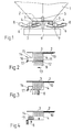
Figur 1 eine schematische Teilansicht eines Zweischeiben-Schleuderstreuers;- Figur 2 - 4 eine schematische Seitenansicht verschiedener Phasen beim Durchtritt eines Wurfflügels durch den Düngerstrahl;
Figur 5 eine schematische Draufsicht auf dieSchleuderscheiben gemäß Figur 1;Figur 6 eine der Figur 5 entsprechende Ansicht einer anderen Ausführungsform undFigur 7 eine Draufsicht einer Schleuderscheibe in einer weiteren Ausführungsform.
- Figure 1 is a schematic partial view of a double disc spreader;
- FIGS. 2-4 show a schematic side view of various phases when a throwing vane passes through the fertilizer jet;
- FIG. 5 shows a schematic top view of the centrifugal disks according to FIG. 1;
- Figure 6 is a corresponding to Figure 5 View of another embodiment and
- Figure 7 is a plan view of a centrifugal disc in a further embodiment.
Der in Figur 1 schematisch und ausschnittsweise wiedergegebene Düngerstreuer weist einen trichterförmigen Vorratsbehälter 1 mit einem Boden 2, darin angeordneten Auslauföffnungen 3 und daran anschließende, die Auslauföffnungen nach unten verlängernde Auslaufschächte 4 auf. Innerhalb des Vorratsbehälters 1 ist ein den Dünger lockernder und rieselfähig haltender Rührer 5 angeordnet. Unterhalb des Bodens 2 des Vorratsbehälters 1 ist unter jedem Auslaufschacht 4 eine Schleuderscheibe 6 angeordnet, deren Drehachse 7 gegenüber dem Auslaufschacht 4 jeweils nach außen versetzt ist. Jede Schleuderscheibe weist wenigstens einen, beim gezeigten Ausführungsbeispiel zwei Wurfflügel 8 auf, die sich vom Zentrum der Schleuderscheibe nach außen erstrecken. Die Schleuderscheiben 6 und der Rührer 5 werden beispielsweise von der Zapfwelle eines Schleppers über Kegelradgetriebe angetrieben, die in dem schematisch wiedergegebenen Getriebegehäuse 9 untergebracht sind.The fertilizer spreader shown schematically and in detail in FIG. 1 has a funnel-shaped
Die Schleuderscheiben 6 sind bei dem in Figur 1 gezeigten Ausführungsbeispiel tellerförmig mit nach oben ansteigender Wandung ausgebildet, so daß auch die Wurfflügel 8 entsprechend geneigt nach oben verlaufen. Diese Ausbildung ist insbesondere für große Streubreiten geeignet, um eine günstige Ballistik für die die Schleuderscheibe 6 verlassenden Düngerpartikel zu erzielen.In the exemplary embodiment shown in FIG. 1, the
In den Figuren 2 bis 4 ist ferner unterhalb der Auslauföffnung 3 ein Dosierschieber 10 erkennbar, mittels dessen der freie Querschnitt der Auslauföffnung 3 und damit die Streumenge eingestellt werden kann. Es ist ferner erkennbar, daß der Auslaufschacht 4 unmittelbar an die Auslauföffnung 3 anschließt und sein Querschnitt etwa dem Querschnitt der Auslauföffnung entspricht, jedenfalls aber nicht kleiner als diese ist. Unmittelbar unterhalb der Unterkante 11 des Auslaufschachtes läuft der Wurfflügel 8 mit seinem oberen Schenkel 12 vorbei, wobei die Umlaufrichtung mit 13 angedeutet ist. Der obere Schenkel 12 kann gegebenenfalls von seiner vorlaufenden Kante nach hinten geneigt sein.In FIGS. 2 to 4, a
Der Auslaufschacht 4 weist in Drehrichtung 13 nach vorne versetzt eine Kammer 14 auf, die beim gezeigten Ausführungsbeispiel von einer Deckwand 15 und einer der Eintrittsseite des Wurfflügels 8 gegenüberliegenden Wandung 16 begrenzt ist. An der Wandung 16 sind außerdem flexible Materialstreifen 17, z. B. in Form von Borsten oder Borstenbündeln, angebracht, die so weit nach unten ragen, daß sie in die Umlaufebene des oberen Schenkels 12 des Wurfflügels 8 hineinragen.The
Beim Vorbeilauf des Wurfflügels werden die im freien Fall den Auslaufschacht 4 durchfallenden Düngerpartikel, wie Figur 2 zeigt, von dem Wurfflügel erfaßt, wobei hier eine idealisierte Darstellung gewählt ist. In Wirklichkeit werden ein großer Teil der Düngerpartikel in verschiedene Richtungen reflektiert. Beim Vorbeilauf des Wurfflügels 8 wird ein Teil der Düngerpartikel innerhalb des Auslaufschachtes 4 nach vorne verdrängt in die Kammer 14 und auch ein Teil der insbesondere von der vorlaufenden Kante des Wurfflügels 8 reflektierten Partikel werden in diese Kammer beschleunigt. Zugleich verdichtet sich der Dünger innerhalb des Wurfflügels, da er während des Vorbeilaufs eine zunehmende Menge in sich aufnimmt. Ein weiterer Anteil der Düngerpartikel wird in die Kammer 14 abgedrängt bis schließlich eine - wiederum idealisiert wiedergegebene - Konstellation gegeben ist, wie sie Figur 4 zeigt.As the spreader vane runs past, the fertilizer particles falling through the
In Figur 5 ist der Boden 2 des Vorratsbehälters 1 strichpunktiert wiedergegeben und sind die beiden Schleuderscheiben 6 mit den Wurfflügeln 8 in Draufsicht erkennbar. Die Wurfflügel sind in diesem Fall zurückgestellt. Es sind weiterhin die Auslaufschächte 4 gezeigt, an die in Umlaufrichtung nach vorne die Kammern 14 anschließen, die bei diesem Ausführungsbeispiel einen - mit Bezug auf die Achse der Schleuderscheiben 6 - von innen nach außen zunehmenden Querschnitt aufweisen. Ferner sind die flexiblen Materialstreifen bzw. Borsten nicht nur an der Wandung des Schachtes 14, sondern auch an der außen liegenden Wandung des Auslaufschachtes angeordnet, so daß sie alle Düngerpartikel, die beim Eintreten des Wurfflügels 8 in den Düngerstrahl nach außen verspritzen könnten, weitestgehend zurückhalten.In Figure 5, the
Bei der Ausführungsform gemäß Figur 6 ist die Querschnittsform der Kammern 14 etwas anders gestaltet, indem der Querschnitt von außen nach innen bzw. bis in einen mittleren Bereich zunimmt.In the embodiment according to FIG. 6, the cross-sectional shape of the
Bei der Ausführungsform gemäß Figur 7 weisen die Wurfflügel 8 in ihrem unterhalb des Auslaufschachtes 4 bzw. der Kammer 14 vorbeilaufenden Abschnitt ein Sägezahnprofil 18 auf. Im Falle eines rückgestellten Wurfflügels 8, wie er in Figur 7 gezeigt ist, weist jeder einzelne Sägezahn eine etwa radial verlaufende Flanke 19 und eine dazu etwa senkrechte Flanke 20 auf, so daß sich über die gesamte Länge der vorlaufenden Kante des Wurfflügels 8 ein ungleichförmiges Sägezahnprofil ergibt.In the embodiment according to FIG. 7, the throwing
Claims (18)
Applications Claiming Priority (2)
| Application Number | Priority Date | Filing Date | Title |
|---|---|---|---|
| DE3906756A DE3906756C2 (en) | 1989-03-03 | 1989-03-03 | Centrifugal spreader |
| DE3906756 | 1989-03-03 |
Publications (4)
| Publication Number | Publication Date |
|---|---|
| EP0385091A2 EP0385091A2 (en) | 1990-09-05 |
| EP0385091A3 EP0385091A3 (en) | 1990-11-22 |
| EP0385091B1 true EP0385091B1 (en) | 1994-01-12 |
| EP0385091B2 EP0385091B2 (en) | 1998-01-07 |
Family
ID=6375411
Family Applications (1)
| Application Number | Title | Priority Date | Filing Date |
|---|---|---|---|
| EP90101259A Expired - Lifetime EP0385091B2 (en) | 1989-03-03 | 1990-01-23 | Broadcaster |
Country Status (2)
| Country | Link |
|---|---|
| EP (1) | EP0385091B2 (en) |
| DE (2) | DE3906756C2 (en) |
Families Citing this family (5)
| Publication number | Priority date | Publication date | Assignee | Title |
|---|---|---|---|---|
| ATE162361T1 (en) * | 1993-07-21 | 1998-02-15 | Rauch Landmaschfab Gmbh | SPRING SPREADERS |
| DE19817742C2 (en) | 1997-05-01 | 2000-04-27 | Rauch Landmaschfab Gmbh | Centrifugal spreader |
| DE102006025823A1 (en) * | 2006-06-02 | 2007-12-06 | Amazonen-Werke H. Dreyer Gmbh & Co. Kg | Centrifugal fertilizer spreader |
| DE102009044852A1 (en) * | 2009-12-10 | 2011-06-16 | Amazonen-Werke H. Dreyer Gmbh & Co. Kg | Broadcaster |
| DE102009044853A1 (en) * | 2009-12-10 | 2011-06-16 | Amazonen-Werke H. Dreyer Gmbh & Co. Kg | Broadcaster |
Family Cites Families (12)
| Publication number | Priority date | Publication date | Assignee | Title |
|---|---|---|---|---|
| FR621096A (en) * | 1926-09-04 | 1927-05-04 | Chute orientation device for adjusting the spreading in disc distributors, fertilizer, seeds and any products | |
| DE919954C (en) * | 1951-03-13 | 1954-11-08 | Lorenz Kircher | Vehicle with spreading device for all kinds of grit |
| CH387363A (en) * | 1960-03-28 | 1965-01-31 | Rausch Martin | Machine for the even distribution of spreadable goods |
| CH382790A (en) * | 1961-01-13 | 1964-10-15 | Kofel Ferdinand | Vehicle for spreading granular material |
| DE1217127B (en) * | 1964-04-27 | 1966-05-18 | Amazonen Werke Dreyer H | Centrifugal spreaders, especially for spreading mineral fertilizers |
| CH443938A (en) * | 1967-02-03 | 1967-09-15 | Gerber Herbert | Sand spreading system on vehicles |
| DE1981011U (en) * | 1967-12-09 | 1968-03-14 | Hans Flender | CENTRIFUGAL SPREADER, IN PARTICULAR FOR THINNING AGENT. |
| DE1937119A1 (en) * | 1969-07-22 | 1971-02-04 | Loewe Pumpenfabrik Gmbh | Centrifugal pump with gas separation |
| US4162766A (en) * | 1977-09-16 | 1979-07-31 | Cuson Stanley N | Vehicular spreader for icy roads and the like |
| DE3035360C2 (en) * | 1980-09-19 | 1982-12-30 | Willy 7715 Bräunlingen Küpper | Spreading vehicle with spreading devices for granulated and liquid thawing substances |
| DD214516A1 (en) * | 1983-04-12 | 1984-10-17 | Adl Der Ddr | FEEDING DEVICE FOR APPLICATION GOODS ON SLUDGE WIPER SPREADERS |
| DE3544060A1 (en) * | 1985-12-13 | 1987-06-19 | Willy Kuepper | Spreading device with liquid supply for spreading moistened granulates |
-
1989
- 1989-03-03 DE DE3906756A patent/DE3906756C2/en not_active Expired - Fee Related
-
1990
- 1990-01-23 EP EP90101259A patent/EP0385091B2/en not_active Expired - Lifetime
- 1990-01-23 DE DE90101259T patent/DE59004168D1/en not_active Expired - Fee Related
Also Published As
| Publication number | Publication date |
|---|---|
| EP0385091A3 (en) | 1990-11-22 |
| EP0385091A2 (en) | 1990-09-05 |
| EP0385091B2 (en) | 1998-01-07 |
| DE59004168D1 (en) | 1994-02-24 |
| DE3906756A1 (en) | 1990-09-06 |
| DE3906756C2 (en) | 1998-05-07 |
Similar Documents
| Publication | Publication Date | Title |
|---|---|---|
| CH641318A5 (en) | SPREADER FOR GRAINY AND / OR POWDERED GOODS. | |
| EP0532055A2 (en) | Distributing method for fertilizer with a broadcaster spreader | |
| DE3804412A1 (en) | SLINGER SPREADER | |
| EP0545894B1 (en) | Broadcaster | |
| EP0385091B1 (en) | Broadcaster | |
| EP0410312B1 (en) | Centrifugal spreader for granular materials, particularly fertilizers | |
| EP0427936B1 (en) | Fertilizer broadcaster | |
| EP0384132B1 (en) | Broadcaster | |
| EP0380040B1 (en) | Broadcaster | |
| EP0410095A1 (en) | A device for spreading granular fertilizer | |
| EP1247437A2 (en) | Method for distributing granular material and centrifugal distributer for carrying out this method | |
| EP0313995A1 (en) | Spreader, especially a disc spreader for fertilizers | |
| EP1031268A1 (en) | Centrifugal fertiliser spreader | |
| DE60104468T2 (en) | Device for distributing granular fertilizer | |
| DE2114467A1 (en) | Seed drill | |
| DE19817742C2 (en) | Centrifugal spreader | |
| DE3902000C2 (en) | Centrifugal spreader | |
| EP0439718B1 (en) | Broadcaster | |
| AT231760B (en) | Centrifugal spreader, especially for mineral fertilizers | |
| DE3924656C1 (en) | ||
| AT200842B (en) | Spreader for agricultural purposes | |
| DE3608935A1 (en) | SLINGER | |
| DD297905A5 (en) | SCHLEUDERDUENGERSTREUER | |
| DE2906791A1 (en) | Granular or powdered fertiliser distributing machine - has diverter plate with sloping guide surfaces between distributor plate and rotating discs | |
| DE3736865A1 (en) | Spreading appliance, especially fertiliser broadcaster |
Legal Events
| Date | Code | Title | Description |
|---|---|---|---|
| PUAI | Public reference made under article 153(3) epc to a published international application that has entered the european phase |
Free format text: ORIGINAL CODE: 0009012 |
|
| AK | Designated contracting states |
Kind code of ref document: A2 Designated state(s): DE FR GB |
|
| PUAL | Search report despatched |
Free format text: ORIGINAL CODE: 0009013 |
|
| AK | Designated contracting states |
Kind code of ref document: A3 Designated state(s): DE FR GB |
|
| 17P | Request for examination filed |
Effective date: 19901221 |
|
| 17Q | First examination report despatched |
Effective date: 19920224 |
|
| GRAA | (expected) grant |
Free format text: ORIGINAL CODE: 0009210 |
|
| AK | Designated contracting states |
Kind code of ref document: B1 Designated state(s): DE FR GB |
|
| PG25 | Lapsed in a contracting state [announced via postgrant information from national office to epo] |
Ref country code: GB Effective date: 19940112 |
|
| REF | Corresponds to: |
Ref document number: 59004168 Country of ref document: DE Date of ref document: 19940224 |
|
| ET | Fr: translation filed | ||
| GBV | Gb: ep patent (uk) treated as always having been void in accordance with gb section 77(7)/1977 [no translation filed] |
Effective date: 19940112 |
|
| PLBI | Opposition filed |
Free format text: ORIGINAL CODE: 0009260 |
|
| 26 | Opposition filed |
Opponent name: MAASLAND N.V. Effective date: 19941012 |
|
| APAA | Appeal reference recorded |
Free format text: ORIGINAL CODE: EPIDOS REFN |
|
| APAC | Appeal dossier modified |
Free format text: ORIGINAL CODE: EPIDOS NOAPO |
|
| APAC | Appeal dossier modified |
Free format text: ORIGINAL CODE: EPIDOS NOAPO |
|
| APAC | Appeal dossier modified |
Free format text: ORIGINAL CODE: EPIDOS NOAPO |
|
| PLAW | Interlocutory decision in opposition |
Free format text: ORIGINAL CODE: EPIDOS IDOP |
|
| PUAH | Patent maintained in amended form |
Free format text: ORIGINAL CODE: 0009272 |
|
| STAA | Information on the status of an ep patent application or granted ep patent |
Free format text: STATUS: PATENT MAINTAINED AS AMENDED |
|
| 27A | Patent maintained in amended form |
Effective date: 19980107 |
|
| AK | Designated contracting states |
Kind code of ref document: B2 Designated state(s): DE FR GB |
|
| ET3 | Fr: translation filed ** decision concerning opposition | ||
| APAH | Appeal reference modified |
Free format text: ORIGINAL CODE: EPIDOSCREFNO |
|
| PGFP | Annual fee paid to national office [announced via postgrant information from national office to epo] |
Ref country code: DE Payment date: 20080116 Year of fee payment: 19 |
|
| PGFP | Annual fee paid to national office [announced via postgrant information from national office to epo] |
Ref country code: FR Payment date: 20080129 Year of fee payment: 19 |
|
| PG25 | Lapsed in a contracting state [announced via postgrant information from national office to epo] |
Ref country code: DE Free format text: LAPSE BECAUSE OF NON-PAYMENT OF DUE FEES Effective date: 20090801 |
|
| REG | Reference to a national code |
Ref country code: FR Ref legal event code: ST Effective date: 20091030 |
|
| PG25 | Lapsed in a contracting state [announced via postgrant information from national office to epo] |
Ref country code: FR Free format text: LAPSE BECAUSE OF NON-PAYMENT OF DUE FEES Effective date: 20090202 |