EP0385016B1 - Savings bank - Google Patents
Savings bank Download PDFInfo
- Publication number
- EP0385016B1 EP0385016B1 EP89302190A EP89302190A EP0385016B1 EP 0385016 B1 EP0385016 B1 EP 0385016B1 EP 89302190 A EP89302190 A EP 89302190A EP 89302190 A EP89302190 A EP 89302190A EP 0385016 B1 EP0385016 B1 EP 0385016B1
- Authority
- EP
- European Patent Office
- Prior art keywords
- coin
- slot
- housing
- savings bank
- barrier
- Prior art date
- Legal status (The legal status is an assumption and is not a legal conclusion. Google has not performed a legal analysis and makes no representation as to the accuracy of the status listed.)
- Expired - Lifetime
Links
Images


Classifications
-
- G—PHYSICS
- G09—EDUCATION; CRYPTOGRAPHY; DISPLAY; ADVERTISING; SEALS
- G09B—EDUCATIONAL OR DEMONSTRATION APPLIANCES; APPLIANCES FOR TEACHING, OR COMMUNICATING WITH, THE BLIND, DEAF OR MUTE; MODELS; PLANETARIA; GLOBES; MAPS; DIAGRAMS
- G09B19/00—Teaching not covered by other main groups of this subclass
- G09B19/18—Book-keeping or economics
-
- A—HUMAN NECESSITIES
- A45—HAND OR TRAVELLING ARTICLES
- A45C—PURSES; LUGGAGE; HAND CARRIED BAGS
- A45C1/00—Purses; Money-bags; Wallets
- A45C1/12—Savings boxes
-
- G—PHYSICS
- G09—EDUCATION; CRYPTOGRAPHY; DISPLAY; ADVERTISING; SEALS
- G09B—EDUCATIONAL OR DEMONSTRATION APPLIANCES; APPLIANCES FOR TEACHING, OR COMMUNICATING WITH, THE BLIND, DEAF OR MUTE; MODELS; PLANETARIA; GLOBES; MAPS; DIAGRAMS
- G09B19/00—Teaching not covered by other main groups of this subclass
Landscapes
- Business, Economics & Management (AREA)
- Engineering & Computer Science (AREA)
- Entrepreneurship & Innovation (AREA)
- Educational Technology (AREA)
- Physics & Mathematics (AREA)
- Educational Administration (AREA)
- General Physics & Mathematics (AREA)
- Theoretical Computer Science (AREA)
- Economics (AREA)
- General Business, Economics & Management (AREA)
- Development Economics (AREA)
- Accounting & Taxation (AREA)
- Control Of Vending Devices And Auxiliary Devices For Vending Devices (AREA)
- Pharmaceuticals Containing Other Organic And Inorganic Compounds (AREA)
- Purses, Travelling Bags, Baskets, Or Suitcases (AREA)
Abstract
Description
- This invention relates to a savings bank. In particular, the invention relates to a savings bank which is educational and is designed to develop the skills of children in the use of banking machines.
- Attempts have been made to provide children's savings banks which have a superficial appearance similar to that of the banking machines presently used by the public for the purposes of carrying banking out transactions. These machines have, however, been simple devices employing mechanical mechanisms which do not function in a manner approaching that of a banking machine.
- The mechanisms used in banking machines to ensure security and to communicate between the banking machine and a central control are so complex as to be quite inappropriate for use in a savings bank of the type of the present invention.
- It is an object of the present invention to provide a portable savings bank which will simulate some of the functions of a banking machine but which is relatively inexpensive to manufacture.
- It is a further object of the present invention to provide a savings bank which will only admit coinage corresponding to the value of the coinage entered by the user.
- According to one aspect of the present invention, there is provided a saving bank comprising;
- a) a housing having a coin storage chamber formed therein,
- b) a plurality of coin slots opening through a front wall of said housing for admitting coins to said chamber,
- c) a plurality of coin barriers, one associated with each coin slot,
- d) activator means for moving each barrier between a first position in which it is arranged to close its associated slot and a second position in which its associated slot is open,
- e) input signal control means having a plurality of manually operable input keys which are selectively operable for operating said activators, said input keys being located on said housing at a point remote from said coin slots and requiring the exercise of selection skill on the part of the operator to select the key or keys which must be manipulated in order to control the operation of the activator which must be activated to open a coin slot through which a particular coin may be admitted to the coin storage chamber.
- The savings bank may include a control means which comprises a keyboard mounted on a wall of the housing such that its keys are accessible to a user, a display panel mounted on a wall of the housing such that it is visible to a user, computer means for receiving a signal from the keyboard which is indicative of the monetary value keyed into the keyboard by a user which is an indication of the value of the coinage to be admitted through one of said coin slots and being programmed to generate an output signal to activate the activator means of the coin slot which is adapted to admit the coinage corresponding in value to the monetary value keyed into the keyboard to move its associated barrier to its second position.
- The invention will be more clearly understood after reference to the following detailed specification read in conjunction with the drawings wherein;
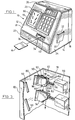
- Figure 1 is a pictorial view of a savings bank constructed in accordance with an embodiment of the present invention,
- Figure 2 is an exploded view of the savinas bank of Figure 1,
- Figure 3 is a view of a portion of the coin slot system taken in the direction of the arrows 3-3 of Figure 2,
- Figure 4 is a pictorial view of the gate used for closing the coin discharge passage,
- Figure 5 is a sectional view of the gate of Figure 4 taken along the line 5-5 of Figure 2.
- Figure 6 is a block diagram illustrating the control system.
- With reference to Figure 1 of the drawings, the
reference numeral 10 refers generally to a savings bank constructed in accordance with an embodiment of the present invention. Thesavings bank 10 has ahousing 12 which is formed from amain enclosure 14 and a movableback wall panel 16. Themain enclosure 14 has a front wall generally identified by thereference numeral 18 which includes an angularlyinclined portion 20 and anupright portion 22. Themain enclosure 14 also includes a pair of oppositely disposedside walls 24, atop wall 26 and a bottom wall 28 (Fig.5). - A
card retaining wall 30 is mounted on aside wall 24 and cooperates therewith to provide acard storage pocket 32. - A
coin discharge passage 34 is formed in theupright portion 22 of the front wall and adoor 36 is mounted in theopening 34. A wall 38 (Fig.2) is located within themain enclosure 14 and serves to form the bottom wall of a coin storage chamber 40 formed within thehousing 12. Thewall 38 has a concave curvature and is shaped so as to direct coins which are supported thereon toward thedischarge passage 34. - A
card access slot 42 is formed in the angularlyinclined portion 20 of the front wall and is proportioned to receive acard 44 which is of similar proportions to a conventional credit card. As shown in Figure 2 of the drawings, a card receiving bracket 46 is provided for receiving a credit card. The bracket 46 includes a base plate 48 which hasside rails 50 extending along opposite side edges thereof, each of which has aflange 52 which overlies an edge portion of the base plate 48 and serves to retain thecard 44 closely adjacent the base plate 48. An end wall 54 extends upwardly from the base plate 48 and serves to form a stop for limiting the extent to which a card can be inserted into theslot 42. Aflange 56 is located at the front end of the base plate 48 and mountingscrews 58 are provided which extend through openings formed in theflange 56 to be threaded into 60 which are formed integrally with the front wall of the housing and serve to retain the card receiving bracket in a position in which the slipway formed therein is aligned with theslot 42. Apassage 62 is formed in the base plate 48 and opens therethrough. - A
switch 64 is mounted on the underside of the base plate 48 and has aswitching arm 66 which projects through thepassage 62 and will extend in a position above the plane of the base plate 48. Theswitching arm 66 is arranged to be moved between a first position and a second position in response to movement of thecard 44 into and out of engagement with the switching arm. - Windows 70, 72 and 74 are formed in the
inclined portion 20 of the front wall. Themarginal edge portions 76 of thewindow openings openings inclined portion 20. - A
coin slot bracket 78 is formed with afront wall 80 and a pair of oppositely disposed side walls 82 (Fig.3). Lugs 84 (Fig.2) are mounted on theside walls 82.Mounting screws 86 are provided for securing thelugs 84 to threaded passages formed in thebosses 88 which are formed integrally with thefront wall 18 of the housing so as to secure thefront wall 80 in a position closing thewindow 70. A plurality ofcoin slots 90 are formed in thefront wall 80 and extend therethrough. Thecoin slots 90 are proportioned to permit coins of different sizes to pass therethrough. Acoin chute 94 is formed with a pair of oppositely disposed side walls 96 and abottom wall 98 arranged to define acoin receiving compartment 100. Theinner edge 102 of thebottom wall 98 is spaced from theinner edges 104 of theside walls 94 by a distance which is less than the diameter of thecoin 106 which is to be admitted through theassociated slot 90. - A
coin barrier 108 is provided at the inner end of eachslipway 92. Thebarrier 108 is in the form of a disc which when located in the position shown in Figure 3 of the drawings serves to retain thecoin 106 in theholding compartment 100. Anactivator 110 is associated with eachslot 90 and is in the form of an electrically operated solenoid which has aram 112 which supports thebarrier 108. A lightweight return spring 114 serves to normally urge the ram toward the extended position. When theactivator solenoid 110 is powered as will be described hereinafter, the ram is retracted in a direction of the arrow shown in Figure 3 to an extent sufficient to displace thebarrier 108 to an extent sufficient to permit thecoin 106 to fall freely from the coin receiving compartment. Theactuators 110 are mounted on theadjacent side walls 82 of thecoin slot bracket 78. - The
coin slots 90 are angularly inclined so that coins falling from the upper coin receiving compartments will not foul the coin receiving compartments located therebelow. - A
board 116 is mounted by means of mountingscrews 118 onbosses 120 formed on the inner face of theinclined wall portion 20 so as to be spaced rearwardly from thewindow 72. Akeyboard 122 is mounted on theboard 116 by means ofsupport posts 124 and are spaced from theboard 116 so as to be located in thewindow 72. A plurality ofkey pads 126 are located on thekeyboard 122 in a configuration customarily used in a conventional pocket calculator. Adisplay panel 128 is mounted on theboard 116 and is arranged to be visible through the window 74. Thedisplay panel 128 may be in the form of a conventional LCD panel of the type commonly used in pocket calculators. - A
battery storage tray 130 is mounted by means of mountingscrews 132 in a position underlying thepassageway 134 which is formed in thetop wall 26. Thetray 130 is proportioned to accommodate a plurality ofbatteries 136 which provide the power source for the control means and all of the powered equipment used in association with the savings bank. Adoor 138 is hingedly mounted on the housing so as to be movable between the closed position shown in Figure 1 and the opened position shown in Figure 2. When thedoor 138 is in the opened position,batteries 136 can be positioned in thetray 130. - The
door 36 which is used for opening and closing thecoin discharge passage 34 will now be described with reference to Figures 4 and 5 of the drawings. - As shown in Figures 4 and 5 of the drawings, an L-
shaped base plate 140 is provided for supporting the door assembly. The L-shaped plate 140 has ahorizontal portion 142 which extends in a face-to-face relationship with thebottom wall 28 of the housing and anupright portion 144 which extends in a face-to-face relationship with respect to theupright portion 22 of the front wall of the housing. Abracket 146 is located one side of theupright portion 144. Abridge plate 148 extends transversely of theupright portion 144 from thebracket 146 to the opposite side edge of theupright portion 144. Thedoor 36 has a rectangularfront panel 150 and a pair of oppositely disposedside wall panels 152 and 154. Theside panels 152 and 154 each have an arcuate-shapededge 156. Ablock 158 is mounted on the outer face of theside wall 152. Apivot pin 160 is mounted in theblock 158 and in theupright post 149 which is located at the adjacent end of thebridge plate 148. A latchingblock 162 is mounted on the side wall 154 by means of mountingscrews 166. Apivot pin 168 extends between thebracket 146 and the latchingbracket 162 so that thedoor 36 can be pivoted between the closed position shown in Figure 4 and the opened position shown in broken lines in Figure 5 by rotation about the axis of the pivot pins 160 and 168. It will be noted that theaxis 164 of the pivot pins 160 and 168 is located in the plane of the upper face of thebottom wall 38.Notches 39 are formed in thebottom wall 38 to accommodate theside walls 152 and 154. An arcuate-shaped cover 170 (only one of which is shown) extends over theside walls 152 and 154 and serves to close theslots 39 to prevent coins discharging through these slots when thedoor 36 is in the opened position. Thecovers 170 each have an arcuate-shapedpassageway 172 which permits free movement of theside walls 152 and 154 and their associated mounting brackets. - The latching
block 162 includes aleg portion 174 which has alug 176 formed thereon and aslot 178 located between thelug 176 and thearm 174. A latchingplate 180 is formed with adetent 182 proportioned to fit in a close-fitting relationship within theslot 178. The latchingplate 180 is mounted on anarm 184 which is pivotally mounted on thebracket 146 by means of apivot pin 186. An H-shapedlink 188 is pivotally connected to thelink arm 184 by means of apivot pin 190. The H-shapedlink 188 is pivotally connected to thehead 192 of aram 194 of asolenoid 196 by means of apivot pin 198. Thesolenoid 196 is mounted in asupport frame 200 which is secured with respect to thehorizontal portion 142 of the L-shapedplate 140. Acompression spring 202 has one end mounted in a recess 204 which is formed in thearm 174. The other end of thecompression spring 202 is arranged to bear against the latchingplate 180. - When the
door 36 is located in the closed position shown in Figure 4 of the drawings and thesolenoid 196 is activated, theram 194 will be drawn inwardly and this will cause thearm 184 to pivot about thepivot pin 186. This movement of thearm 184 will cause thedetent 182 of thelatch plate 180 to be withdrawn from theslot 178. Thecompression spring 202 will then urge thedoor 36 to the partially opened position shown in solid lines in Figure 5. In this position, thedoor 36 can be manually engaged so as to be opened to the position shown in broken lines in Figure 5. Coins which are located within the coin storage chamber can then be removed through thecoin discharge opening 34. The signal which is used to activate thesolenoid 196 is of a short duration and is only required to perform the step of removing thedetent 182 from theslot 178. It follows that almost immediately after the door has been unlatched, thesolenoid 196 is deactivated to return theram 194 to the position shown in Figure 4 of the drawings. Thedoor 36 can be latched in the closed position shown in Figure 4 by merely manually pivoting the door to the closed position. The pressure applied by thespring 202 to thelatch plate 180 will have the effect of driving thedetent 182 into the blockingslot 178 in order to relock thedoor 36 in the closed position. - Figure 6 of the drawings is a block diagram illustrating the control system.
- The control system includes a central processing unit (CPU) 206. A suitable CPU is a Motorola MC146805E2 CPU manufactured by Motorola Inc. which has adeauate decoding and ram capacity. The CPU communicates with the 16-
key keyboard 122 to receive input signals therefrom. An eprom 208 such as a 27C-16 is programmed with a suitable program for controlling the operation of the CPU. Aprimary power source 210 which may be in the form of 4 of 6 1.5 volt D cell batteries is provided for the purposes of powering the CPU. A back-up power source (not shown) is provided for powering the CPU to provide memory retention capabilities. The CPU communicates with each of the coin slot solenoids 110. The CPU also communicates with thedoor opening solenoid 196, andcard sensing switch 64. - Appropriate markings will be provided on the
front wall 80 adjacent each coin slot to identify the coin which each slot is proportioned to accommodate. Theslots 90 may be proportioned to accommodate coins such as a dime, a 1-cent piece, a nickel, a quarter, a 50-cent piece and a one-dollar coin or the coinage of any other monetary system in which the size of the coin is related to the monetary value of the coin. - In use, the appropriate coin is inserted into the corresponding slots. The coin will be retained in the coin storage compartment and will not be released into the coin storage chamber until a key-pad or combination of key-pads are present in order to register on the display a monetary value corresponding to the value of the coin located in the coin-retaining compartment. The CPU will then activate the
appropriate solenoid 110 to move it up to the open position to permit the coin which is located in the corresponding storage compartment to fall freely into the coin storage chamber. This process can be repeated so as to deposit a plurality of coins of the same or different monetary value through their appropriate slots. To activate the CPU, thecard 44 must first be inserted into theslot 42 to the point where it moves theswitch arm 66 to the position closing theswitch 64 to activate the system. The system will remain activated while thecard 44 remains in theslot 42 in the position retaining theswitch 64 in its closed position. - Various modifications of the savings bank of the present invention will be apparent to those skilled in the art without departing from the scope of the invention.
- For example, covers may be provided over the
coin chutes 94 to prevent the coins which have dropped from above passing into the underlying chutes. In addition, sensors may be provided in the coin storage chamber for indicating when the coin storage chamber is full or has been filled to the maximum desired extent. The additional sensors may communicate with the CPU to generate a signal which can be displayed on the display indicating that the coin storage chamber is full. - In a further modification, the barriers which close the coin slots may be mounted for movement transversely of the
slipways 92 by arranging the solenoids at right angles to theslipways 92. In addition, thecoin slots 90 may be vertically oriented. These and other modifications of the present invention will be apparent to those skilled in the art.
Claims (7)
- A savings bank comprising;a) a housing having a coin storage chamber formed therein,b) a plurality of coin slots opening through a front wall of said housing for admitting coins to said chamber,c) a plurality of coin barriers, one associated with each coin slot,d) activator means for moving each barrier between a first position in which it is arranged to close its associated slot and a second position in which its associated slot is open,e) input signal control means having a plurality of manually operable input keys which are selectively operable for operating said activators, said input keys being located on said housing at a point remote from said coin slots and requiring the exercise of selection skill on the part of the operator to select the key or keys which must be manipulated in order to control the operation of the activator which must be activated to open a coin slot through which a particular coin may be admitted to the coin storage chamber.
- A savings bank as claimed in claim 1, wherein said input signal control means further comprises;a) a keyboard comprising said keys mounted on a wall of the housing such that said keys are accessible to a user,b) a display panel mounted on a wall of the housing such that it is visible to user,c) computer means for receiving a signal from the keyboard which is indicative of the monetary value keyed into the keyboard by a user which is an indication of the value of the coinage to be admitted through one of said coin slots and serving to generate an output signal to activate the activator means of the coin slot which is adapted to admit the coinage corresponding in value to the monetary value keyed into the keyboard to move its associated barrier to its second position.
- A savings bank as claimed in claims 1 or 2, further comprising a switch for selectively activating and deactivating said control means, said switch being located in said housing so as to be inaccessible to direct contact by the user, an access slot opening into said housing at a point which is remote from said coin slots and communicating with said switch to permit a card to gain access to said switch to activate said switch when the card is located in a predetermined position within said access slot in use.
- A savings bank as claimed in claim 1, wherein each activator means comprises a solenoid and each coin barrier is movable by its associated solenoid so as to be located in its first and second positions.
- A savings bank as claimed in claims 1, 2, 3 or 4, further comprising a discharge passage communicating with said chamber, a door in said discharge passage which can be opened or closed to permit or prevent the discharge of coins from said chamber, latch means in said housing for releaseably retaining said door in said closed position, said latch means communicating with said input signal control means so as to be operable in response to the manual operation of one or more of said manually operated input keys to release said latch means to permit said door to open as require in use.
- A savings bank as claimed in claims 1, 2, 3, 4 or 5, wherein said coin slots are each proportioned to pass a coin of a different size.
- A savings bank as claimed in claims 1, 2, 3, 4, 5 or 6, wherein a coin chute is associated with each coin slot, each coin chute having an open upper end and extends inwardly and downwardly within said chamber from its associated slot to form a holding compartment in which a coin may be retained within the housing by the barrier associated with the associated coin slot until said barrier is moved to its opened position.
Applications Claiming Priority (1)
| Application Number | Priority Date | Filing Date | Title |
|---|---|---|---|
| US07/039,024 US4811828A (en) | 1987-04-16 | 1987-04-16 | Savings bank |
Publications (2)
| Publication Number | Publication Date |
|---|---|
| EP0385016A1 EP0385016A1 (en) | 1990-09-05 |
| EP0385016B1 true EP0385016B1 (en) | 1995-10-11 |
Family
ID=21903259
Family Applications (1)
| Application Number | Title | Priority Date | Filing Date |
|---|---|---|---|
| EP89302190A Expired - Lifetime EP0385016B1 (en) | 1987-04-16 | 1989-03-03 | Savings bank |
Country Status (5)
| Country | Link |
|---|---|
| US (1) | US4811828A (en) |
| EP (1) | EP0385016B1 (en) |
| AT (1) | ATE129087T1 (en) |
| DE (1) | DE68924528T2 (en) |
| ES (1) | ES2081835T3 (en) |
Families Citing this family (10)
| Publication number | Priority date | Publication date | Assignee | Title |
|---|---|---|---|---|
| US4998611A (en) * | 1989-09-25 | 1991-03-12 | William Shuie | Coin distinguishing mechanism for a coin keeper |
| ES2079286B1 (en) * | 1993-09-23 | 1997-11-01 | Compania Electronica De Tecnic | DEVICE FOR THE PROGRAMMED SAVING OF COINS WITH A BUILT-IN NOTICE. |
| ES2122939B1 (en) * | 1997-05-07 | 1999-08-01 | Plaza Miranzo Jose | ELECTRONIC PURSE WITH VOICE. |
| WO2002074125A1 (en) * | 2001-02-02 | 2002-09-26 | Kyeong-Hwan Kim | Saving box having recreation function |
| BE1015005A3 (en) * | 2002-01-29 | 2004-08-03 | Chinek Nourredine | Electronic wallet has sensors to determine type of money placed in wallet and keyboard for controlled access to money |
| US20080293019A1 (en) * | 2007-05-22 | 2008-11-27 | Dooley Christopher P | Money Storage Device with Separately Interactive Virtual Teller |
| EP2897107A1 (en) * | 2014-01-15 | 2015-07-22 | Wincor Nixdorf International GmbH | Flap device with a light element |
| USD964480S1 (en) * | 2020-12-28 | 2022-09-20 | Shuzhong Guo | Cash register toy |
| USD993567S1 (en) * | 2022-08-30 | 2023-07-25 | Li Tian | Coin bank |
| USD1022383S1 (en) * | 2024-01-02 | 2024-04-09 | Wenshang Wang | Piggy bank |
Family Cites Families (14)
| Publication number | Priority date | Publication date | Assignee | Title |
|---|---|---|---|---|
| US32115A (en) * | 1861-04-23 | John A Brock | Improved mining-pan | |
| US29796A (en) * | 1860-08-28 | Sad-ibon | ||
| US1259605A (en) * | 1916-06-26 | 1918-03-19 | Hobbs Mfg Company | Coin-controlled apparatus. |
| US2267857A (en) * | 1938-08-20 | 1941-12-30 | Firm Sodeco Soc Des Compteurs | Control device of prepayment meters |
| US3792764A (en) * | 1972-09-15 | 1974-02-19 | Glory Kogyo Kk | Device for automatic closure of coin slot of rental locker |
| CH624501A5 (en) * | 1977-07-29 | 1981-07-31 | Sodeco Compteurs De Geneve | Collecting device for a coin collector |
| EP0022437A3 (en) * | 1979-07-13 | 1981-07-22 | Mordechai Meirovitz | Vending machine game apparatus |
| CH646000A5 (en) * | 1979-10-01 | 1984-10-31 | Autelca Ag | Automatic coin collector |
| US4282674A (en) * | 1980-02-04 | 1981-08-11 | Marvin Glass & Associates | Toy cash register |
| US4427389A (en) * | 1982-04-19 | 1984-01-24 | Arco Industries Ltd. | Toy coin changer |
| FR2526188A1 (en) * | 1982-04-28 | 1983-11-04 | Gesi | CURRENCY STORE FOR PAYMENT SYSTEM, WITH CASH AND RENDERING OF CURRENCY |
| KR910006691B1 (en) * | 1984-11-09 | 1991-08-31 | 유우겐가이샤 보난자 엔터프라이제즈 | Liquid crystal display game apparatus with savings box |
| US4673368A (en) * | 1986-07-17 | 1987-06-16 | Playtronics Corporation | Toy bank with novel coin discriminating mechanism |
| US4682288A (en) * | 1986-08-21 | 1987-07-21 | Brandt, Inc. | Electronic control for totaling denominations of several countries |
-
1987
- 1987-04-16 US US07/039,024 patent/US4811828A/en not_active Expired - Fee Related
-
1989
- 1989-03-03 AT AT89302190T patent/ATE129087T1/en active
- 1989-03-03 ES ES89302190T patent/ES2081835T3/en not_active Expired - Lifetime
- 1989-03-03 DE DE68924528T patent/DE68924528T2/en not_active Expired - Fee Related
- 1989-03-03 EP EP89302190A patent/EP0385016B1/en not_active Expired - Lifetime
Also Published As
| Publication number | Publication date |
|---|---|
| EP0385016A1 (en) | 1990-09-05 |
| US4811828A (en) | 1989-03-14 |
| DE68924528T2 (en) | 1996-05-09 |
| ATE129087T1 (en) | 1995-10-15 |
| ES2081835T3 (en) | 1996-03-16 |
| DE68924528D1 (en) | 1995-11-16 |
Similar Documents
| Publication | Publication Date | Title |
|---|---|---|
| EP0385016B1 (en) | Savings bank | |
| US6623006B2 (en) | Gaming machine | |
| US6412654B1 (en) | Vending machine | |
| CA2047655A1 (en) | Computer-controlled coin parking meter | |
| US7241222B2 (en) | Air cooling configuration for gaming machine | |
| US6146274A (en) | Cabinet and hopper combination for gaming machines including a controller and monitor for opening and closing thereof | |
| US5360093A (en) | Method and apparatus for the control of a multiple of door accessible newspaper vending cabinets with a single vend control mechanism operating remote door latches | |
| US20050032578A1 (en) | Slant-type gaming machine | |
| WO2005029226A2 (en) | Slant-type gaming machine | |
| US1949283A (en) | Depository | |
| WO2006043074A2 (en) | Keypad security device | |
| US4236649A (en) | Compact vending machine | |
| DE3067663D1 (en) | Money container for cash registers | |
| US5016262A (en) | Cash caddy | |
| US4311227A (en) | Vending system for floral type products | |
| CA1302378C (en) | Savings bank | |
| JP2002000798A (en) | Game machine | |
| JPH02241405A (en) | Saving box | |
| US20060070559A1 (en) | Unitary currency/credit card unit | |
| EP0071455A2 (en) | Improvements introduced in slot machines | |
| JP2001347021A (en) | Ball shooting game machine | |
| US3283897A (en) | Bill acceptance and detection system | |
| JP2683810B2 (en) | Ball rental supply pipe | |
| US3193819A (en) | Alarms for parking meters | |
| CN207718470U (en) | A kind of Currency output mechanism of coin automatic depositing-withdrawing changer |
Legal Events
| Date | Code | Title | Description |
|---|---|---|---|
| PUAI | Public reference made under article 153(3) epc to a published international application that has entered the european phase |
Free format text: ORIGINAL CODE: 0009012 |
|
| AK | Designated contracting states |
Kind code of ref document: A1 Designated state(s): AT BE CH DE ES FR GB GR IT LI LU NL SE |
|
| 17P | Request for examination filed |
Effective date: 19910304 |
|
| 17Q | First examination report despatched |
Effective date: 19930426 |
|
| GRAA | (expected) grant |
Free format text: ORIGINAL CODE: 0009210 |
|
| AK | Designated contracting states |
Kind code of ref document: B1 Designated state(s): AT BE CH DE ES FR GB GR IT LI LU NL SE |
|
| PG25 | Lapsed in a contracting state [announced via postgrant information from national office to epo] |
Ref country code: NL Free format text: LAPSE BECAUSE OF FAILURE TO SUBMIT A TRANSLATION OF THE DESCRIPTION OR TO PAY THE FEE WITHIN THE PRESCRIBED TIME-LIMIT Effective date: 19951011 Ref country code: GR Free format text: LAPSE BECAUSE OF FAILURE TO SUBMIT A TRANSLATION OF THE DESCRIPTION OR TO PAY THE FEE WITHIN THE PRESCRIBED TIME-LIMIT Effective date: 19951011 Ref country code: BE Effective date: 19951011 Ref country code: AT Effective date: 19951011 |
|
| REF | Corresponds to: |
Ref document number: 129087 Country of ref document: AT Date of ref document: 19951015 Kind code of ref document: T |
|
| REF | Corresponds to: |
Ref document number: 68924528 Country of ref document: DE Date of ref document: 19951116 |
|
| ITF | It: translation for a ep patent filed |
Owner name: JACOBACCI & PERANI S.P.A. |
|
| PG25 | Lapsed in a contracting state [announced via postgrant information from national office to epo] |
Ref country code: SE Effective date: 19960111 |
|
| ET | Fr: translation filed | ||
| NLV1 | Nl: lapsed or annulled due to failure to fulfill the requirements of art. 29p and 29m of the patents act | ||
| PG25 | Lapsed in a contracting state [announced via postgrant information from national office to epo] |
Ref country code: GB Effective date: 19960303 |
|
| PG25 | Lapsed in a contracting state [announced via postgrant information from national office to epo] |
Ref country code: ES Free format text: LAPSE BECAUSE OF NON-PAYMENT OF DUE FEES Effective date: 19960304 |
|
| REG | Reference to a national code |
Ref country code: ES Ref legal event code: FG2A Ref document number: 2081835 Country of ref document: ES Kind code of ref document: T3 |
|
| PG25 | Lapsed in a contracting state [announced via postgrant information from national office to epo] |
Ref country code: LU Free format text: LAPSE BECAUSE OF NON-PAYMENT OF DUE FEES Effective date: 19960331 Ref country code: LI Effective date: 19960331 Ref country code: CH Effective date: 19960331 |
|
| REG | Reference to a national code |
Ref country code: FR Ref legal event code: CA |
|
| PLBE | No opposition filed within time limit |
Free format text: ORIGINAL CODE: 0009261 |
|
| STAA | Information on the status of an ep patent application or granted ep patent |
Free format text: STATUS: NO OPPOSITION FILED WITHIN TIME LIMIT |
|
| 26N | No opposition filed | ||
| GBPC | Gb: european patent ceased through non-payment of renewal fee |
Effective date: 19960303 |
|
| REG | Reference to a national code |
Ref country code: CH Ref legal event code: PL |
|
| PG25 | Lapsed in a contracting state [announced via postgrant information from national office to epo] |
Ref country code: FR Effective date: 19961129 |
|
| PG25 | Lapsed in a contracting state [announced via postgrant information from national office to epo] |
Ref country code: DE Effective date: 19961203 |
|
| REG | Reference to a national code |
Ref country code: FR Ref legal event code: ST |
|
| REG | Reference to a national code |
Ref country code: ES Ref legal event code: FD2A Effective date: 19990503 |
|
| PG25 | Lapsed in a contracting state [announced via postgrant information from national office to epo] |
Ref country code: IT Free format text: LAPSE BECAUSE OF NON-PAYMENT OF DUE FEES Effective date: 20050303 |