EP0384885B1 - Distributor for single-pieces - Google Patents
Distributor for single-pieces Download PDFInfo
- Publication number
- EP0384885B1 EP0384885B1 EP90810044A EP90810044A EP0384885B1 EP 0384885 B1 EP0384885 B1 EP 0384885B1 EP 90810044 A EP90810044 A EP 90810044A EP 90810044 A EP90810044 A EP 90810044A EP 0384885 B1 EP0384885 B1 EP 0384885B1
- Authority
- EP
- European Patent Office
- Prior art keywords
- conveyor belt
- transfer device
- sensor
- conveyor
- transfer apparatus
- Prior art date
- Legal status (The legal status is an assumption and is not a legal conclusion. Google has not performed a legal analysis and makes no representation as to the accuracy of the status listed.)
- Expired - Lifetime
Links
Images


Classifications
-
- B—PERFORMING OPERATIONS; TRANSPORTING
- B65—CONVEYING; PACKING; STORING; HANDLING THIN OR FILAMENTARY MATERIAL
- B65G—TRANSPORT OR STORAGE DEVICES, e.g. CONVEYORS FOR LOADING OR TIPPING, SHOP CONVEYOR SYSTEMS OR PNEUMATIC TUBE CONVEYORS
- B65G47/00—Article or material-handling devices associated with conveyors; Methods employing such devices
- B65G47/74—Feeding, transfer, or discharging devices of particular kinds or types
- B65G47/84—Star-shaped wheels or devices having endless travelling belts or chains, the wheels or devices being equipped with article-engaging elements
- B65G47/846—Star-shaped wheels or wheels equipped with article-engaging elements
Definitions
- the present invention relates to a distributor of individual pieces according to the preamble of patent claim 1.
- a transfer device is provided with a plurality of suction trolleys, which are arranged by means of arms about a central axis.
- Each suction trolley is provided with a suction device and a valve tappet for controlling the vacuum, which is actuated by the single piece to be picked up, so that the suction air is released and the single piece is held in the suction device.
- the suction cups are designed so that they can be rotated by 90 degrees so that the individual pieces located on the conveyor belt of the feed section maintain their position when they are released onto the conveyor belt of the receiving section.
- the known transfer device does indeed cause the individual pieces to be transferred correctly from one encoder machine to a cartoning machine, but is very complex with regard to the suction cups, which are rotatable by 90 ° and work with vacuum.
- the present invention is therefore based on the object of providing a distributor of small individual pieces with a less expensive transfer device.
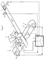
- the distributor shown in Fig. 1 has a conveyor track 1, which can be set in motion between two conveyors 2 and 3, the conveyor tracks 2 'and 3' of the conveyor 2 or 3 and the conveyor track 1, at least approximately in one plane are located.
- a single piece 4, for example a packaged chocolate bar, lies on the conveyor track 1.
- a transfer device 5 is arranged, which has an impeller 6, a servo motor 7 and one Encoder 8 comprises, which is connected to a processor or computer 9, which also supplies signals for a servo motor 10 of the conveyor 2 and for a servo motor 11 of the conveyor 3.
- a sensor 12 is arranged directly in front of the transfer device 5 in the direction of movement of the conveyor track 1; and preferably about 2 piece lengths in front of it is a second sensor 13, the processor 9 being connected to these sensors 12 and 13 as well as to a further encoder 14 synchronized with the conveyor track 1.
- the conveyors 2 and 3 and the transfer device 5 are shown with some details to show that the conveyors each have an auxiliary conveyor 15, 15 '.
- the conveyor 2 and the auxiliary conveyor 15 have a common roller 16 with four grooves or grooves, two with the inner diameter D and two with the inner diameter d, D being greater than d.
- Conveyors 2 and / or 3 preferably have no conveyor belts, but two round belts each, of which only one round belt 18 or 19 is visible in FIG. 2, which are inserted into the grooves with diameter D.
- auxiliary conveyor 15, 15 'each comprise two chain belts, which are inserted into the grooves with the diameter d, and of which only one chain belt 20 or 21 is visible in FIG. 2.
- These Chain belts are provided with holding links 22 and 23, which are preferably distributed at regular intervals.
- the transfer device 5 shown in FIG. 2 has an impeller with six blades, the edge of the blade 24 being in the vicinity of a single piece 4 lying on the conveyor track 1.
- the holding members 22 are outside the area defined by the round belts 18, 18 '.
- the holding links 22 according to FIG. 2 are located within the area mentioned to indicate that both types of construction are possible, with instead of round and chain belts e.g. V-belts or flat belts could also be used.
- Fig. 3 several individual pieces 4 are shown both on the conveyor track or the conveyor belt 1 and on the pairs of belts 18, 18 'and 19, 19'. From the transfer device, only two wings 25, 25 'are visible in Fig. 3.
- the distance between the axis 26 of the impeller and the outer edge of a Wing 24 is slightly smaller than the distance between this axis 26 and the area determined by the round belts 18, 18 'on which the individual pieces 4 lie.
- the holding members 22, 22 'on the outside with respect to the round belts 18, 18'.
- the wings each have a central slot 27, 27 'to create a free space for a guide bar 28 which is arranged perpendicular to the axis 26 and slightly above the individual pieces 4.
- the optional guide bar 28 is not shown in FIGS. 1 to 3. This guide bar can be straight or partially curved.
- the distributor according to FIGS. 1 to 4 now works as follows: First of all, it should be noted that the distributor can also work with only one of the conveyors 2 or 3, that the sensor 12 is omitted for some applications, and that the impeller must have at least two blades or a blade and a counterweight.
- the processor 9 can determine the position of a reference point of the conveyor track 1 at any moment by means of the signals supplied by the encoder 14.
- the processor 9 can use the signals supplied by the sensor 13 (FIG. 1) to determine when the front edge of a single piece 4 is just at the sensor 13 passes by. With this information, the processor 9 can supply the encoder 8 with signals which controls the servo motor 7 in such a way that a wing 24 (FIG. 2) of the transfer device 5 gives an impact to a single piece 4 when it is in a centered position with respect to it located on the conveyor track 2 ', so that the single piece lands on the conveyor track 2' and is held by the holding members 22.
- the processor 9 can also control the servo motor 10 in such a way that the individual pieces 4 arrive at the conveyor track 2 'at a certain cycle or at predetermined intervals.
- the sensor 12 serves to detect the position of the pieces on the feed belt or the conveyor track 1. If after switching on the distributor there are pieces between the two sensors 12 and 13 whose position is not known, they are detected by the sensor 12 and then, for example encountered on the conveyor track 3 'by rotating the impeller 6 in the other direction.
- the processor 9 can perform a so-called software shift register function as follows: As soon as the sensor 13 detects a beginning of a piece, a one is written into the register, which is currently displayed. Its address is recorded in a so-called address flag and the counter is deleted. With each cycle from the encoder 14, the counter is increased by one and the reader and writer are shifted up by one address. Registered the Sensor 13 again a piece start, the counter content is stored under the address that is in the address flag, the new recorder address is recorded in the address flag and the counter is deleted. After a shift register length, the reader now reads the values that the writer has written into it.
- the transfer device runs at a speed at which one revolution corresponds to the average distance between the pieces. The corresponding value is subtracted from the counter and added to the address in the address flag. The one in the shift register is now saved in this new address in the shift register. It should be noted that the impeller should rotate continuously and should not be reduced to zero speed.
- the distributor can have, for example, three proximity switches, which are used when positioning the motors when switching on or during a reset.
- the transfer device has an open belt drive with two rollers 30, 31, at least one pin 33 being attached to the belt 32.
- the belt drive according to FIG. 5 is arranged transversely over the conveyor track 1, preferably in such a way that the axes of the rollers 30, 31 run parallel to the conveyor track 1.
- the belt drive works in such a way that at a predetermined time the pin 33 moves the piece 4 from the center of the conveyor track 1 to the conveyor track 2 'or 3'.
- the distributor according to the invention can not only work with one of the conveyors 2 or 3, but also when the power is divided between the two conveyors.
- a storage function is also possible in that pieces that are on one of the conveyor tracks 2 'or 3' are moved via the stationary conveyor track 1 to the other conveyor track 3 'or 2'.
- the distributor is reversible, which means that the conveyor track 1 can serve not only as a feed track but also as a receiving track.
- Light barriers can serve as sensors, for example.
Description
Die vorliegende Erfindung betrifft einen Verteiler von Einzelstücken gemäss dem Oberbegriff des Patentanspruchs 1.The present invention relates to a distributor of individual pieces according to the preamble of
Aus der DE-A- 25 51 538 ist eine Vorrichtung zum Zuführen und Einlegen von Einzelstücken in die Aufnahmetaschen der Förderkette einer Kartoniermaschine bekannt. Zu diesem Zweck ist eine Uebergabevorrichtung mit einer Vielzahl von Saugerwagen vorgesehen, welche mittels Armen um eine zentrale Achse angeordnet sind. Jeder Saugerwagen ist zur Aufnahme eines Einzelstücks mit einem Sauger sowie mit einem dem Steuern des Vakuums dienenden Ventilstössel versehen, wobei dieser durch das aufzunehmende Einzelstück betätigt wird, so dass die Saugluft freigegeben und das Einzelstück im Sauger festgehalten wird. Damit die auf dem Förderband der Zufuhrstrecke befindlichen Einzelstücke bei der Abgabe auf das Förderband der Aufnahmestrecke ihre Lage beibehalten, sind die Sauger um 90 Grad drehbar ausgebildet.From DE-A-25 51 538 a device for feeding and inserting individual pieces into the receiving pockets of the conveyor chain of a cartoning machine is known. For this purpose, a transfer device is provided with a plurality of suction trolleys, which are arranged by means of arms about a central axis. Each suction trolley is provided with a suction device and a valve tappet for controlling the vacuum, which is actuated by the single piece to be picked up, so that the suction air is released and the single piece is held in the suction device. The suction cups are designed so that they can be rotated by 90 degrees so that the individual pieces located on the conveyor belt of the feed section maintain their position when they are released onto the conveyor belt of the receiving section.
Die bekannte Uebergabevorrichtung, deren zentrale Achse senkrecht zu beiden Förderbändern angeordnet ist, bewirkt zwar eine einwandfreie Uebergabe der Einzelstücke von einer Geber maschine zu einer Kartoniermaschine, ist jedoch sehr aufwendig im Hinblick auf die Sauger, die um 90° drehbar ausgebildet sind und mit Vakuum arbeiten.The known transfer device, the central axis of which is arranged perpendicular to both conveyor belts, does indeed cause the individual pieces to be transferred correctly from one encoder machine to a cartoning machine, but is very complex with regard to the suction cups, which are rotatable by 90 ° and work with vacuum.
Aus der US-A- 4 356 908 ist eine Verteilereinrichtung die mit einer Platte zur Verschiebung der Einzelstücke versehener Riemantrieb arbeitet, bekannt.From US-A-4 356 908 a distributor device which works with a plate for moving the individual pieces provided belt drive is known.
Aus der US-A- 4,057,138 ist ferner eine Verteilereinrichtung für grosse Baumstämme bekannt, aus denen Sägemehl für die Papierfabrikation produziert wird. Diese Verteilereinrichtung ist mit mehreren koaxial angetriebenen Verteilervorrichtungen versehen, um die Baumstämme parallel zur Baumachse verschieben zu können. Eine solche Verteilereinrichtung ist nicht geeignet, um kleine Einzelstücke wie Schokoladeriegel zu transportieren.From US-A-4,057,138 a distributor device for large tree trunks is also known, from which sawdust for paper manufacture is produced. This distributor device is provided with a plurality of coaxially driven distributor devices in order to be able to move the tree trunks parallel to the tree axis. Such a distribution device is not suitable for transporting small individual pieces such as chocolate bars.
Der vorliegenden Erfindung liegt daher die Aufgabe zugrunde, einen Verteiler von kleinen Einzelstücken mit einer weniger aufwendigen Uebergabevorrichtung zu schaffen.The present invention is therefore based on the object of providing a distributor of small individual pieces with a less expensive transfer device.
Diese Aufgabe wird erfindungsgemäss durch einen Verteiler mit den im kennzeichnenden Teil des Patentanspruchs 1 angegebenen Merkmalen gelöst.This object is achieved according to the invention by a distributor with the features specified in the characterizing part of
Andere vorteilhafte Ausgestaltungen der Erfindung sind in weiteren Ansprüchen angegeben.Other advantageous embodiments of the invention are specified in further claims.
Die Erfindung wird nachfolgend durch Beschreibung von Ausführungsbeispielen anhand einer Zeichnung näher beschrieben. Es zeigt:
- Fig. 1
- eine schematische Darstellung eines erfindungsgemässen Verteilers,
- Fig. 2
- eine Seitenansicht einer Uebergabevorrichtung zwischen zwei Förderern nach der Erfindung,
- Fig. 3
- eine Draufsicht einer solchen Uebergabevorrichtung,
- Fig. 4
- eine Querschnittdarstellung des Flügelrades einer Uebergabevorrichtung nach einer ersten Ausführung der Erfindung,
- Fig. 5
- eine schematische Seitenansicht einer weiteren Ausführung einer Uebergabevorrichtung nach der Erfindung.
- Fig. 1
- 2 shows a schematic representation of a distributor according to the invention,
- Fig. 2
- a side view of a transfer device between two conveyors according to the invention,
- Fig. 3
- a plan view of such a transfer device,
- Fig. 4
- 2 shows a cross-sectional illustration of the impeller of a transfer device according to a first embodiment of the invention,
- Fig. 5
- is a schematic side view of another embodiment of a transfer device according to the invention.
Der in Fig. 1 dargestellte Verteiler weist eine Förderbahn 1 auf, die zwischen zwei Förderern 2 und 3 in Bewegung gesetzt werden kann, wobei die Förderbahnen 2′ und 3′ der Förderer 2 bzw. 3 und die Förderbahn 1 sich zumindest angenähert in einer Ebene befinden. Auf der Förderbahn 1 liegt ein Einzelstück 4, beispielsweise ein verpackter Schokoladeriegel. Im Bereich zwischen den zwei Förderern 2 und 3, jedoch oberhalb derselben ist eine Uebergabevorrichtung 5 angeordnet, die ein Flügelrad 6, einen Servomotor 7 und einen Encoder 8 umfasst, der an einen Prozessor oder Rechner 9 angeschlossen ist, der auch Signale für einen Servomotor 10 des Förderers 2 und für einen Servomotor 11 des Förderers 3 liefert. Unmittelbar vor der Uebergabevorrichtung 5 in der Bewegungsrichtung der Förderbahn 1 ist ein Sensor 12 angeordnet; und vorzugsweise etwa 2 Stücklängen vor ihm befindet sich ein zweiter Sensor 13, wobei der Prozessor 9 sowohl an diese Sensoren 12 und 13 als auch an einen weiteren, mit der Förderbahn 1 synchronisierten Encoder 14 angeschlossen ist.The distributor shown in Fig. 1 has a
In Fig. 2 sind die Förderer 2 und 3 und die Uebergabevorrichtung 5 mit einigen Details dargestellt, um zu zeigen, dass die Förderer je einen Hilfsförderer 15, 15′ aufweisen. Der Förderer 2 und der Hilfsförderer 15 haben eine gemeinsame Rolle 16 mit vier Rillen oder Nuten, und zwar zwei mit dem Innendurchmesser D und zwei mit dem Innendurchmesser d, wobei D grösser als d ist. Entsprechendes gilt für eine Rolle 17 bezüglich der Förderer 3 und 15′. Die Förderer 2 und/oder 3 weisen vorzugsweise keine Förderbänder, sondern je zwei Rundriemen auf, von denen in der Fig. 2 nur je ein Rundriemen 18 bzw. 19 sichtbar ist, die in die Rillen mit dem Durchmesser D eingesetzt sind. Demgegenüber können die Hilfsförderer 15, 15′ je zwei Kettenriemen umfassen, die in die Rillen mit dem Durchmesser d eingesetzt sind, und von denen in der Fig. 2 nur je ein Kettenriemen 20 bzw. 21 sichtbar ist. Diese Kettenriemen sind mit Haltegliedern 22 bzw. 23 versehen, die vorzugsweise in regelmässigen Abständen verteilt sind. Die in Fig. 2 dargestellte Uebergabevorrichtung 5 weist ein Flügelrad mit sechs Flügeln auf, wobei die Kante des Flügels 24 sich in der Nähe eines auf der Förderbahn 1 liegenden Einzelstücks 4 befindet.2, the
In Fig. 3 sind die zwei Rundriemenpaare 18, 18′ und 19, 19′ des Förderers 2 bzw. 3 und zur Vereinfachung der Zeichnung nur einige Halteglieder 22, 23 ohne die Kettenriemen dargestellt.In Fig. 3, the two pairs of
In der Ausführung nach Fig. 3 befinden sich die Halteglieder 22 ausserhalb der von den Rundriemen 18, 18′ bestimmten Fläche. Im Gegensatz dazu befinden sich die Halteglieder 22 nach Fig. 2 innerhalb der erwähnten Fläche, um anzudeuten, dass beide Ausführungsarten möglich sind, wobei anstelle von Rund- und Kettenriemen z.B. auch Keil- oder Flachriemen eingesetzt werden könnten. In Fig. 3 sind mehrere Einzelstücke 4 sowohl auf der Förderbahn oder dem Förderband 1 als auch auf den Riemenpaaren 18, 18′ und 19, 19′ dargestellt. Von der Uebergabevorrichtung sind in Fig. 3 nur zwei Flügel 25, 25′ sichtbar.3, the
Ferner ist aus Fig. 4 ersichtlich, dass der Abstand zwischen der Achse 26 des Flügelrades und der äusseren Kante eines Flügels 24 etwas kleiner als der Abstand zwischen dieser Achse 26 und der von den Rundriemen 18, 18′ bestimmten Fläche ist, auf der die Einzelstücke 4 liegen. In Fig. 4 liegen die Halteglieder 22, 22′ aussenseitig in bezug auf die Rundriemen 18, 18′. Die Flügel weisen je einen mittig verlaufenden Schlitz 27, 27′ auf, um einen freien Raum für eine Führungsleiste 28 zu schaffen, die senkrecht zur Achse 26 und etwas oberhalb der Einzelstücke 4 angeordnet ist. Zur Vereinfachung der Zeichnung ist die fakultative Führungsleiste 28 in den Figuren 1 bis 3 nicht dargestellt. Diese Führungsleiste kann geradlinig oder zum Teil gebogen sein.4 that the distance between the
Der Verteiler nach den Figuren 1 bis 4 funktioniert nun folgendermassen:
Zunächst ist festzuhalten, dass der Verteiler auch mit nur einem der Förderer 2 oder 3 arbeiten kann, dass für einige Anwendungen der Sensor 12 entfällt, und dass das Flügelrad mindestens zwei Flügel oder einen Flügel und ein Gegengewicht aufweisen muss.The distributor according to FIGS. 1 to 4 now works as follows:
First of all, it should be noted that the distributor can also work with only one of the
Durch die vom Encoder 14 gelieferten Signale kann der Prozessor 9 die Lage eines Referenzpunktes der Förderbahn 1 in jedem Moment bestimmen. Durch die vom Sensor 13 (Fig. 1) gelieferten Signale kann der Prozessor 9 bestimmen, wann die vordere Kante eines Einzelstücks 4 gerade beim Sensor 13 vorbeigeht. Mit diesen Angaben kann der Prozessor 9 dem Encoder 8 Signale liefern, die den Servomotor 7 derart steuert, dass ein Flügel 24 (Fig. 2) der Uebergabevorrichtung 5 gerade dann einem Einzelstück 4 einen Stoss gibt, wenn es sich in einer zentrierten Lage in bezug auf die Förderbahn 2′ befindet, so dass das Einzelstück auf der Förderbahn 2′ landet und von den Haltegliedern 22 gehalten wird. Dabei kann der Prozessor 9 auch den Servomotor 10 derart steuern, dass die Einzelstücke 4 in einem bestimmten Takt oder in vorbestimmten Abständen auf die Förderbahn 2′ gelangen. Der Sensor 12 dient zur Erfassung der Position der Stücke auf dem Zufuhrband oder der Förderbahn 1. Wenn nach Einschalten des Verteilers Stücke zwischen den zwei Sensoren 12 und 13 liegen, deren Position man nicht kennt, so werden sie durch den Sensor 12 erfasst und dann beispielsweise auf die Förderbahn 3′ gestossen, indem das Flügelrad 6 in die andere Richtung gedreht wird.The
Der Prozessor 9 kann eine sogenannte Software-Schieberegister-Funktion wie folgt ausüben:
Sobald der Sensor 13 einen Stückanfang detektiert, wird eine Eins in das Register eingeschrieben, das momentan angezeigt wird. Seine Adresse wird in einem sogenannten Adress-Merker festgehalten und der Zähler gelöscht. Bei jedem Takt vom Encoder 14 wird der Zähler um eins erhöht und Leser und Schreiber um eine Adresse hinaufgeschoben. Registriert der Sensor 13 erneut einen Stückanfang, so wird der Zählerinhalt unter diejenige Adresse gespeichert, die im Adress-Merker steht, die neue Schreiberadresse wird im Adress-Merker festgehalten und der Zähler gelöscht. Der Leser liest nun nach einer Schieberegisterlänge die Werte, die der Schreiber hineingeschrieben hat. Liest der Leser eine Null, so wird nichts unternommen, liest er eine Zahl grösser als eins, so wird dies als ein Abstand zwischen zwei Stücken aufgefasst, woraus eine Uebersetzung für das elektronische Getriebe gerechnet werden muss. Liest der Leser eine Eins, so bedeutet das, dass immer noch kein neues Stück beim Sensor 13 angekommen ist. In diesem Fall läuft die Uebergabevorrichtung mit einer Geschwindigkeit, bei der eine Umdrehung dem mittleren Abstand zwischen den Stücken entspricht. Der entsprechende Wert wird vom Zähler subtrahiert und zur Adresse im Adress-Merker addiert. Die Eins im Schieberegister wird nun unter dieser neuen Adresse im Schieberegister gespeichert. Dabei muss bemerkt werden, dass das Flügelrad kontinuierlich drehen und nicht auf Geschwindigkeit null reduziert werden soll.The
As soon as the
Der Verteiler kann beispielsweise drei Annäherungsschalter aufweisen, die bei der Positionierung der Motoren beim Einschalten oder bei einem Reset gebraucht werden.The distributor can have, for example, three proximity switches, which are used when positioning the motors when switching on or during a reset.
Die Uebergabevorrichtung nach Fig. 5 weist einen offenen Riementrieb mit zwei Rollen 30, 31 auf, wobei am Riemen 32 mindestens ein Stift 33 befestigt ist. Der Riementrieb nach Fig. 5 wird quer über die Förderbahn 1 angeordnet, vorzugsweise derart, dass die Achsen der Rollen 30, 31 parallel zur Förderbahn 1 verlaufen. Der Riementrieb funktioniert in der Weise, dass in einem vorbestimmten Zeitpunkt der Stift 33 das Stück 4 von der Mitte der Förderbahn 1 auf die Förderbahn 2′ oder 3′ verschiebt.The transfer device according to FIG. 5 has an open belt drive with two
Der erfindungsgemässe Verteiler kann nicht nur mit einem der Förderer 2 oder 3, sondern auch bei einer Leistungsaufteilung auf beide Förderer arbeiten.The distributor according to the invention can not only work with one of the
Dabei ist auch eine Speicherfunktion möglich, indem Stücke, die sich auf einer der Förderbahnen 2′ oder 3′ befinden, über die stillstehende Förderbahn 1 auf die andere Förderbahn 3′ bzw. 2′ versetzt werden.A storage function is also possible in that pieces that are on one of the conveyor tracks 2 'or 3' are moved via the
Der Verteiler ist reversibel, das heisst, die Förderbahn 1 kann nicht nur als Zufuhrbahn, sondern auch als Aufnahmebahn dienen.The distributor is reversible, which means that the
Als Sensoren können beispielsweise Lichtschranken dienen.Light barriers can serve as sensors, for example.
Claims (9)
- Transfer apparatus for packaged single items having a rotatable transfer device for transferring single items which are conveyed lying on a first conveyor belt onto a second conveyor belt, wherein the rotational axis of the rotatable transfer device is situated in a plane parallel to the first conveyor belt (1), characterised in that the transfer device is centrally situated over a region of the first conveyor belt (1), wherein on the left and right of this first conveyor belt (1) and perpendicular to it a second (2′) and a third (3′) conveyor belt are respectively disposed, that a processor (9) is provided which supplies signals for controlling the transfer device (5) and a respective servodrive (10;11) for driving the second and third conveyor belt (2′;3′) respectively in order to be able to displace a single item (4) from the centre of the first conveyor belt (1) onto the second or onto the third conveyor belt (2';3'), and that either the transfer device (5) comprises an impeller wheel (6), which is rotatable about a rotational axis, having at least one radially disposed arm (24) of which the edge comprises at least one slot (27) in order to leave a free space for a guide bead (28) of which at least a part is situated above the space provided for the passage of the single items (4) and is disposed perpendicular to the rotational axis (26) of the impeller wheel, or the transfer device is a belt drive disposed transversely over the first conveyor belt (1) and which belt drive is provided with at least one pin (33) to displace the individual items (4).
- Transfer apparatus according to claim 1, characterised in that the belt drive comprises two rollers (30,31), the axes of which extend parallel to the first conveyor belt (1) and predetermine a plane, wherein the distance between this plane and the conveyor plane of the first conveyor belt is approximately equal to or is smaller than the diameter of the rollers (30,31).
- Transfer apparatus according to claim 1 or 2, characterised in that it is reversible and renders possible a storage function in order to transfer single items, which are situated on the left or right conveyor belt (2′;3′), over the stationary first conveyor belt (1) onto the other conveyor belt (3′ or 2′).
- Transfer apparatus according to one of claims 1 to 3, characterised in that the second and/or third conveyor belt (2′;3′) comprises two parallel driven belts (18,18′;19, 19′).
- Transfer apparatus according to claim 4, characterised in that the second and/or third conveyor belt (2′; 3′) is a component part of a conveyor (2, 3) which comprises an additional conveyor (15;15′), the belts of which (20;21) are provided with retaining members (22;23).
- Transfer apparatus according to one of claims 1 to 5, characterised in that the first conveyor belt (1) is kinematically connected to an encoder (14).
- Transfer apparatus according to claim 6, characterised in that the processor (9) predetermines, by means of the signals supplied by this first encoder (14), the position at each moment of a reference point of the first conveyor belt (1), that the processor (9) predetermines, by means of the signals supplied by a first sensor (13), when a single item (4) has just passed by this first sensor (13), and that the processor (9) having this data supplies signals to a second encoder (8) in order to control the transfer device (5).
- Transfer apparatus according to claim 7, characterised in that immediately in front of the transfer device (5) in the direction of movement of the first conveyor belt (1) a second sensor (12) is disposed which sensor 12 is connected at the processor (9), that the first sensor (13) is situated at a distance in front of the second sensor (12) which serves to detect the position of the single items on the rest of the conveyor belt (1) if, after the transfer apparatus is switched on, single items lie between the two sensors (12, 13) and their position is not known, and that such individual items are detected by the second sensor (12) and are pushed onto a side conveyor belt (3′) by rotating the transfer device (5) into the other direction.
- Transfer apparatus according to claim 6, characterised in that the output of at least one sensor (13), which supplies a signal to detect the position of an individual item (4) on the first conveyor belt (1), and the output of this encoder (14) are connected to the processor (9).
Applications Claiming Priority (2)
| Application Number | Priority Date | Filing Date | Title |
|---|---|---|---|
| CH60689 | 1989-02-20 | ||
| CH606/89 | 1989-02-20 |
Publications (3)
| Publication Number | Publication Date |
|---|---|
| EP0384885A2 EP0384885A2 (en) | 1990-08-29 |
| EP0384885A3 EP0384885A3 (en) | 1991-01-09 |
| EP0384885B1 true EP0384885B1 (en) | 1994-07-06 |
Family
ID=4190891
Family Applications (1)
| Application Number | Title | Priority Date | Filing Date |
|---|---|---|---|
| EP90810044A Expired - Lifetime EP0384885B1 (en) | 1989-02-20 | 1990-01-19 | Distributor for single-pieces |
Country Status (5)
| Country | Link |
|---|---|
| US (1) | US5052542A (en) |
| EP (1) | EP0384885B1 (en) |
| JP (1) | JPH02233416A (en) |
| DE (1) | DE59006330D1 (en) |
| ES (1) | ES2055393T3 (en) |
Cited By (1)
| Publication number | Priority date | Publication date | Assignee | Title |
|---|---|---|---|---|
| CN1648023B (en) * | 2004-01-28 | 2011-01-26 | E.C.H.威尔股份有限公司 | Method as well as apparatus for transverse conveyance of reams |
Families Citing this family (37)
| Publication number | Priority date | Publication date | Assignee | Title |
|---|---|---|---|---|
| EP0580815B1 (en) * | 1991-04-15 | 1998-01-21 | Lorillard Tobacco Company | Sortation system for cigarette packs |
| US5275272A (en) * | 1993-04-06 | 1994-01-04 | Sandvik Process Systems, Inc. | Conveyor system with article diverting mechanism |
| AUPN244495A0 (en) * | 1995-04-13 | 1995-05-11 | 3M Australia Pty Limited | Sorting device and method |
| DE19542846A1 (en) * | 1995-11-17 | 1997-05-22 | Spuehl Ag | Spring transport device with servo drive |
| DE19736567C1 (en) | 1997-08-22 | 1998-11-26 | Select Ingenieurgesellschaft F | Arrangement for sorting products according to their characteristics e.g. in foodstuffs industry |
| EP0904854B1 (en) * | 1997-09-15 | 2002-11-13 | Siemens Aktiengesellschaft | Device for sorting articles |
| DE19827235C1 (en) | 1998-06-18 | 2000-02-10 | Bell & Howell Co | Mail processing machine |
| DE19851780A1 (en) * | 1998-11-10 | 2000-05-11 | Will E C H Gmbh & Co | Device for discharging sheet layers from a conveyor line |
| US6264042B1 (en) * | 1999-11-15 | 2001-07-24 | United Parcel Service Of America, Inc. | Bilateral sorter |
| US6505728B1 (en) * | 2000-03-24 | 2003-01-14 | Gemofor Inc. | Lumber transfer system |
| WO2001072614A1 (en) * | 2000-03-31 | 2001-10-04 | Tomra Systems Asa | Apparatuses for the conveying, lifting and sorting of articles |
| EP1424211B1 (en) * | 2002-11-29 | 2006-05-03 | Müller Martini Holding AG | Device for the production of bound printed products |
| NZ534244A (en) | 2004-07-20 | 2007-05-31 | Foodcap Int Ltd | Product distribution methods and apparatus |
| JP2008516855A (en) | 2004-10-15 | 2008-05-22 | フードキャップ インターナショナル リミテッド | Container, lid and clip for it |
| US9097452B2 (en) | 2004-10-15 | 2015-08-04 | Foodcap International Limited | Methods and apparatus for thermal regulation of perishable products |
| JP2008516872A (en) * | 2004-10-18 | 2008-05-22 | フードキャップ インターナショナル リミテッド | Apparatus and method for processing and distribution of fresh food |
| SE527834C2 (en) * | 2004-11-10 | 2006-06-13 | Norden Pac Dev Ab | Cardboard machine apparatus and method |
| PL1947614T3 (en) | 2005-01-25 | 2019-04-30 | Tomra Systems Asa | Conveyor means for returnable items |
| MXPA05009225A (en) * | 2005-08-30 | 2007-02-27 | Grupo Bimbo Sa De Cv | Machine for automatically supplying plates and/or moulds for bakery products to a forming line. |
| NL1030192C2 (en) * | 2005-10-14 | 2007-04-17 | Stork Townsend Bv | Device and method for transferring elongated food products. |
| DE102012003604A1 (en) * | 2012-02-21 | 2013-08-22 | Kolbus Gmbh & Co. Kg | Device for feeding book blocks in the import channel of a further processing device |
| CN102897520A (en) * | 2012-10-15 | 2013-01-30 | 江苏圆通农机科技有限公司 | Material poking device with scraper blades |
| US9327914B1 (en) * | 2013-08-22 | 2016-05-03 | Millard Manufacturing Corp. | Rotary sweep arm system |
| CN103552836B (en) * | 2013-10-21 | 2016-01-20 | 江苏永钢集团有限公司 | A kind of kiln powder ash process units |
| JP6309305B2 (en) * | 2014-02-26 | 2018-04-11 | 大和製衡株式会社 | Sorting device |
| CN105415871A (en) * | 2015-11-27 | 2016-03-23 | 荣昌精密机械(苏州)有限公司 | Printing assembly line mechanism |
| GB201703134D0 (en) * | 2017-02-27 | 2017-04-12 | Beers Uk Ltd | Dispensing apparatus |
| JP6930720B2 (en) * | 2017-04-21 | 2021-09-01 | 一壽 大月 | New free tray type fruit sorting equipment |
| CN108177962A (en) * | 2017-12-08 | 2018-06-19 | 桐乡胜辉精密机械有限公司 | A kind of workpiece feed mechanism |
| FR3082127B1 (en) * | 2018-06-12 | 2021-12-03 | Prot Decoration Conditionnement P D C Europe | INSTALLATION OF SCROLLING OBJECT SELECTION ON A TRANSFER LINE |
| AU2019368359A1 (en) * | 2018-10-25 | 2021-06-03 | And Y Knot Innovation And Sales Inc. | Stacking and packaging device |
| CN109592308A (en) * | 2018-11-30 | 2019-04-09 | 河南易成新能源股份有限公司 | Machine adds automatic feeding and method |
| FR3098208B1 (en) * | 2019-07-01 | 2023-10-27 | Semso | DEVICE FOR CONVEYING FILIFORM PRODUCTS AT HIGH SPEED AND METHOD FOR IMPLEMENTING |
| CN112811148B (en) * | 2020-12-29 | 2022-06-21 | 江苏华工激光科技有限公司 | Material distributing device |
| CN113213061A (en) * | 2021-05-13 | 2021-08-06 | 湖北瑞佳不锈钢有限公司 | Stainless steel kettle body transmission device |
| DE102021123023A1 (en) * | 2021-09-06 | 2023-03-09 | Wipotec Gmbh | sorting device |
| CN116119301B (en) * | 2022-12-30 | 2023-09-19 | 徐州华睿炭材料科技有限公司 | Processing equipment of active carbon package |
Family Cites Families (20)
| Publication number | Priority date | Publication date | Assignee | Title |
|---|---|---|---|---|
| US2049112A (en) * | 1930-07-07 | 1936-07-28 | Newton Steel Company | Sheet feeding apparatus |
| AT123451B (en) * | 1930-07-19 | 1931-06-25 | Friedrich Ing Lerner | Device for sorting and placing cigarettes in an orderly manner on cigarette rod machines. |
| FR914140A (en) * | 1944-10-31 | 1946-09-30 | Device for loading a hopper or other member comprising a cavity to be filled | |
| US2981410A (en) * | 1957-02-05 | 1961-04-25 | Filper Corp | Apparatus for sorting pit carrying drupe halves from pit free drupe halves |
| US2957572A (en) * | 1957-05-02 | 1960-10-25 | Ferro Corp | Multiple strand conveyor |
| US3071239A (en) * | 1958-10-28 | 1963-01-01 | Stewart Warner Corp | Conveyor unloading mechanism |
| US3246733A (en) * | 1962-08-22 | 1966-04-19 | Fmc Corp | Article handling mechanism |
| US3363741A (en) * | 1966-09-21 | 1968-01-16 | Owens Illinois Inc | Article conveying apparatus |
| US3515254A (en) * | 1968-08-27 | 1970-06-02 | Leo A Gary | Conveyor system having computer for finding the centers of objects being conveyed |
| US3701407A (en) * | 1971-02-02 | 1972-10-31 | Emhart Corp | Glassware transfer mechanism |
| DE2551538A1 (en) * | 1975-11-17 | 1977-05-26 | Karlsruhe Augsburg Iweka | TRANSFER DEVICE FOR EASILY DEFORMABLE PACKAGING GOODS |
| US4057138A (en) * | 1976-02-05 | 1977-11-08 | Wisconsin Bridge & Iron Co. | Apparatus for routing logs |
| US4216854A (en) * | 1978-07-13 | 1980-08-12 | Avon Products, Inc. | Feeding apparatus with engaged/disengaged transport mechanism |
| US4356908A (en) * | 1979-05-25 | 1982-11-02 | The Mead Corporation | Method and apparatus for aligning and separating containers of diverse shapes |
| SE8100247L (en) * | 1981-01-19 | 1982-07-20 | Tetra Pak Int | SET AND APPARATUS FOR FORMAL FEEDING |
| US4765940A (en) * | 1984-09-21 | 1988-08-23 | American Technical Industries, Inc. | Method of transporting and forming tapered ends on piquets |
| US4635786A (en) * | 1985-01-11 | 1987-01-13 | Hershey Foods Corporation | Orientation section of packing apparatus |
| US4771877A (en) * | 1987-05-05 | 1988-09-20 | H. J. Langen & Sons Limited | Load spacing conveyor system |
| JPS6456226A (en) * | 1987-08-25 | 1989-03-03 | Mazda Motor | Vehicle ventilation device |
| US4832178A (en) * | 1988-05-12 | 1989-05-23 | Apv Douglas Machine Corporation | Container metering device |
-
1989
- 1989-12-29 JP JP1345031A patent/JPH02233416A/en active Pending
-
1990
- 1990-01-19 ES ES90810044T patent/ES2055393T3/en not_active Expired - Lifetime
- 1990-01-19 DE DE59006330T patent/DE59006330D1/en not_active Expired - Fee Related
- 1990-01-19 EP EP90810044A patent/EP0384885B1/en not_active Expired - Lifetime
- 1990-02-20 US US07/481,593 patent/US5052542A/en not_active Expired - Fee Related
Cited By (1)
| Publication number | Priority date | Publication date | Assignee | Title |
|---|---|---|---|---|
| CN1648023B (en) * | 2004-01-28 | 2011-01-26 | E.C.H.威尔股份有限公司 | Method as well as apparatus for transverse conveyance of reams |
Also Published As
| Publication number | Publication date |
|---|---|
| US5052542A (en) | 1991-10-01 |
| EP0384885A3 (en) | 1991-01-09 |
| JPH02233416A (en) | 1990-09-17 |
| EP0384885A2 (en) | 1990-08-29 |
| DE59006330D1 (en) | 1994-08-11 |
| ES2055393T3 (en) | 1994-08-16 |
Similar Documents
| Publication | Publication Date | Title |
|---|---|---|
| EP0384885B1 (en) | Distributor for single-pieces | |
| DE2358185C2 (en) | Sorting device with separating line and sorting line | |
| DE3248788C2 (en) | Device for rotating an object through a given angle about a vertical axis | |
| DE60105549T2 (en) | DEVICE FOR REPOSITING PRODUCTS WHILE MAINTAINING THE FORWARD SPEED | |
| CH686709A5 (en) | Automatic rotary sorter for packages | |
| DE602004011057T2 (en) | SORTING DEVICE | |
| EP1846309B1 (en) | Apparatus and method for sorting unordered containers in an order picking system | |
| DE2342445A1 (en) | PALLETIZING DEVICE | |
| DE102011104900B4 (en) | Device for defined layer formation of conveyed material | |
| EP0396960A2 (en) | Method and installation for rearranging objects palletized in classes in to groups of definite sorting composition | |
| DE2752193C2 (en) | Transport device for series products within a weighing device | |
| DE4105273A1 (en) | DEVICE FOR STACKING PACKING UNITS | |
| DE69722253T2 (en) | METHOD AND DEVICE FOR CONVEYING VOLUMINOUS PACKING UNITS, SUCH AS e.g. CONTAINERS | |
| DE2261463A1 (en) | MACHINE FOR STEP BY STEP FEEDING A SERIES OF CONTAINERS BETWEEN A NUMBER OF STATIONS | |
| DE10155596B4 (en) | Device for stacking plates brought up along a plate conveyor | |
| DE4335196B4 (en) | Device for feeding in and out of objects during transport routes | |
| WO1992000905A1 (en) | Device for turning small objects, in particular parcels, on a conveyor belt | |
| EP1574459A1 (en) | Device and method for the transfer of parallelepipedal products in a certain position | |
| EP1105327A2 (en) | Array for individualizing contiguous packages | |
| EP0305755A2 (en) | Feeding conveyor for feeding piece-goods onto an accepting conveyor | |
| EP0882405B1 (en) | Shackle for supporting poultry bodies | |
| DE3906084A1 (en) | METHOD AND DEVICE FOR PARALLEL ALIGNING OF TIMBER | |
| DE3705802C2 (en) | ||
| DE3412025A1 (en) | COMPUTER-CONTROLLED PICKING WAREHOUSE | |
| EP0588144A1 (en) | Sorting machine with transporting devices |
Legal Events
| Date | Code | Title | Description |
|---|---|---|---|
| PUAI | Public reference made under article 153(3) epc to a published international application that has entered the european phase |
Free format text: ORIGINAL CODE: 0009012 |
|
| AK | Designated contracting states |
Kind code of ref document: A2 Designated state(s): CH DE ES FR GB IT LI NL |
|
| PUAL | Search report despatched |
Free format text: ORIGINAL CODE: 0009013 |
|
| AK | Designated contracting states |
Kind code of ref document: A3 Designated state(s): CH DE ES FR GB IT LI NL |
|
| 17P | Request for examination filed |
Effective date: 19910412 |
|
| 17Q | First examination report despatched |
Effective date: 19920430 |
|
| GRAA | (expected) grant |
Free format text: ORIGINAL CODE: 0009210 |
|
| AK | Designated contracting states |
Kind code of ref document: B1 Designated state(s): CH DE ES FR GB IT LI NL |
|
| GBT | Gb: translation of ep patent filed (gb section 77(6)(a)/1977) |
Effective date: 19940704 |
|
| REF | Corresponds to: |
Ref document number: 59006330 Country of ref document: DE Date of ref document: 19940811 |
|
| REG | Reference to a national code |
Ref country code: ES Ref legal event code: FG2A Ref document number: 2055393 Country of ref document: ES Kind code of ref document: T3 |
|
| ITF | It: translation for a ep patent filed |
Owner name: STUDIO TORTA SOCIETA' SEMPLICE |
|
| ET | Fr: translation filed | ||
| PLBE | No opposition filed within time limit |
Free format text: ORIGINAL CODE: 0009261 |
|
| STAA | Information on the status of an ep patent application or granted ep patent |
Free format text: STATUS: NO OPPOSITION FILED WITHIN TIME LIMIT |
|
| 26N | No opposition filed | ||
| PGFP | Annual fee paid to national office [announced via postgrant information from national office to epo] |
Ref country code: CH Payment date: 19960105 Year of fee payment: 7 |
|
| PGFP | Annual fee paid to national office [announced via postgrant information from national office to epo] |
Ref country code: FR Payment date: 19961209 Year of fee payment: 8 |
|
| PGFP | Annual fee paid to national office [announced via postgrant information from national office to epo] |
Ref country code: ES Payment date: 19970116 Year of fee payment: 8 |
|
| PG25 | Lapsed in a contracting state [announced via postgrant information from national office to epo] |
Ref country code: LI Effective date: 19970131 Ref country code: CH Effective date: 19970131 |
|
| REG | Reference to a national code |
Ref country code: CH Ref legal event code: PL |
|
| PGFP | Annual fee paid to national office [announced via postgrant information from national office to epo] |
Ref country code: GB Payment date: 19971218 Year of fee payment: 9 |
|
| PGFP | Annual fee paid to national office [announced via postgrant information from national office to epo] |
Ref country code: DE Payment date: 19971222 Year of fee payment: 9 |
|
| PG25 | Lapsed in a contracting state [announced via postgrant information from national office to epo] |
Ref country code: ES Free format text: LAPSE BECAUSE OF NON-PAYMENT OF DUE FEES Effective date: 19980120 |
|
| PGFP | Annual fee paid to national office [announced via postgrant information from national office to epo] |
Ref country code: NL Payment date: 19980130 Year of fee payment: 9 |
|
| PG25 | Lapsed in a contracting state [announced via postgrant information from national office to epo] |
Ref country code: FR Free format text: THE PATENT HAS BEEN ANNULLED BY A DECISION OF A NATIONAL AUTHORITY Effective date: 19980131 |
|
| REG | Reference to a national code |
Ref country code: FR Ref legal event code: ST |
|
| PG25 | Lapsed in a contracting state [announced via postgrant information from national office to epo] |
Ref country code: GB Free format text: LAPSE BECAUSE OF NON-PAYMENT OF DUE FEES Effective date: 19990119 |
|
| PG25 | Lapsed in a contracting state [announced via postgrant information from national office to epo] |
Ref country code: NL Free format text: LAPSE BECAUSE OF NON-PAYMENT OF DUE FEES Effective date: 19990801 |
|
| GBPC | Gb: european patent ceased through non-payment of renewal fee |
Effective date: 19990119 |
|
| PG25 | Lapsed in a contracting state [announced via postgrant information from national office to epo] |
Ref country code: DE Free format text: LAPSE BECAUSE OF NON-PAYMENT OF DUE FEES Effective date: 19991103 |
|
| REG | Reference to a national code |
Ref country code: ES Ref legal event code: FD2A Effective date: 20010503 |
|
| PG25 | Lapsed in a contracting state [announced via postgrant information from national office to epo] |
Ref country code: IT Free format text: LAPSE BECAUSE OF NON-PAYMENT OF DUE FEES;WARNING: LAPSES OF ITALIAN PATENTS WITH EFFECTIVE DATE BEFORE 2007 MAY HAVE OCCURRED AT ANY TIME BEFORE 2007. THE CORRECT EFFECTIVE DATE MAY BE DIFFERENT FROM THE ONE RECORDED. Effective date: 20050119 |