EP0384085B1 - Improved tank retaining strip for heat exchangers - Google Patents
Improved tank retaining strip for heat exchangers Download PDFInfo
- Publication number
- EP0384085B1 EP0384085B1 EP89313716A EP89313716A EP0384085B1 EP 0384085 B1 EP0384085 B1 EP 0384085B1 EP 89313716 A EP89313716 A EP 89313716A EP 89313716 A EP89313716 A EP 89313716A EP 0384085 B1 EP0384085 B1 EP 0384085B1
- Authority
- EP
- European Patent Office
- Prior art keywords
- strip
- hook
- heat exchanger
- flange
- apertures
- Prior art date
- Legal status (The legal status is an assumption and is not a legal conclusion. Google has not performed a legal analysis and makes no representation as to the accuracy of the status listed.)
- Expired - Lifetime
Links
- 230000015572 biosynthetic process Effects 0.000 claims description 30
- 238000005755 formation reaction Methods 0.000 claims description 30
- 210000001331 nose Anatomy 0.000 claims description 19
- 230000002093 peripheral effect Effects 0.000 claims description 10
- 238000010276 construction Methods 0.000 description 10
- 238000010494 dissociation reaction Methods 0.000 description 8
- 230000005593 dissociations Effects 0.000 description 8
- 238000007789 sealing Methods 0.000 description 5
- 239000000463 material Substances 0.000 description 3
- 239000002184 metal Substances 0.000 description 3
- 229910052751 metal Inorganic materials 0.000 description 3
- 238000007906 compression Methods 0.000 description 2
- 239000007788 liquid Substances 0.000 description 2
- 229910001369 Brass Inorganic materials 0.000 description 1
- WYTGDNHDOZPMIW-RCBQFDQVSA-N alstonine Natural products C1=CC2=C3C=CC=CC3=NC2=C2N1C[C@H]1[C@H](C)OC=C(C(=O)OC)[C@H]1C2 WYTGDNHDOZPMIW-RCBQFDQVSA-N 0.000 description 1
- 239000004411 aluminium Substances 0.000 description 1
- 229910052782 aluminium Inorganic materials 0.000 description 1
- XAGFODPZIPBFFR-UHFFFAOYSA-N aluminium Chemical compound [Al] XAGFODPZIPBFFR-UHFFFAOYSA-N 0.000 description 1
- 230000000903 blocking effect Effects 0.000 description 1
- 239000010951 brass Substances 0.000 description 1
- 230000001351 cycling effect Effects 0.000 description 1
- 239000000446 fuel Substances 0.000 description 1
- 238000009434 installation Methods 0.000 description 1
- 230000014759 maintenance of location Effects 0.000 description 1
Images


Classifications
-
- F—MECHANICAL ENGINEERING; LIGHTING; HEATING; WEAPONS; BLASTING
- F28—HEAT EXCHANGE IN GENERAL
- F28F—DETAILS OF HEAT-EXCHANGE AND HEAT-TRANSFER APPARATUS, OF GENERAL APPLICATION
- F28F9/00—Casings; Header boxes; Auxiliary supports for elements; Auxiliary members within casings
-
- F—MECHANICAL ENGINEERING; LIGHTING; HEATING; WEAPONS; BLASTING
- F28—HEAT EXCHANGE IN GENERAL
- F28F—DETAILS OF HEAT-EXCHANGE AND HEAT-TRANSFER APPARATUS, OF GENERAL APPLICATION
- F28F9/00—Casings; Header boxes; Auxiliary supports for elements; Auxiliary members within casings
- F28F9/02—Header boxes; End plates
- F28F9/0219—Arrangements for sealing end plates into casing or header box; Header box sub-elements
- F28F9/0224—Header boxes formed by sealing end plates into covers
- F28F9/0226—Header boxes formed by sealing end plates into covers with resilient gaskets
-
- F—MECHANICAL ENGINEERING; LIGHTING; HEATING; WEAPONS; BLASTING
- F28—HEAT EXCHANGE IN GENERAL
- F28F—DETAILS OF HEAT-EXCHANGE AND HEAT-TRANSFER APPARATUS, OF GENERAL APPLICATION
- F28F2275/00—Fastening; Joining
- F28F2275/08—Fastening; Joining by clamping or clipping
-
- Y—GENERAL TAGGING OF NEW TECHNOLOGICAL DEVELOPMENTS; GENERAL TAGGING OF CROSS-SECTIONAL TECHNOLOGIES SPANNING OVER SEVERAL SECTIONS OF THE IPC; TECHNICAL SUBJECTS COVERED BY FORMER USPC CROSS-REFERENCE ART COLLECTIONS [XRACs] AND DIGESTS
- Y10—TECHNICAL SUBJECTS COVERED BY FORMER USPC
- Y10T—TECHNICAL SUBJECTS COVERED BY FORMER US CLASSIFICATION
- Y10T403/00—Joints and connections
- Y10T403/70—Interfitted members
- Y10T403/7045—Interdigitated ends
Definitions
- each of the formations is hook-like with the hook-part of the hook-like formation lodged against a side of the upstanding flange oppositely of the strip.
- Figs. 10 and 11 show still another embodiment of the invention.
- This embodiment also makes use of the resiliency of the seal 30.
- trapezoidal apertures 90 are utilized and have their major bases 92 downwardly and their minor bases 94 remote from the surface 28.
- the hook-like formations are T-shaped as shown at 96 and have oppositely directed noses 98 extending from the base of the finger 100.
Landscapes
- Engineering & Computer Science (AREA)
- Physics & Mathematics (AREA)
- Thermal Sciences (AREA)
- Mechanical Engineering (AREA)
- General Engineering & Computer Science (AREA)
- Heat-Exchange Devices With Radiators And Conduit Assemblies (AREA)
- Filling Or Discharging Of Gas Storage Vessels (AREA)
- Details Of Heat-Exchange And Heat-Transfer (AREA)
Description
- This invention relates to a heat exchanger comprising the features as indicated in the precharacterizing part of claim 1.
- Such heat exchanger is for example known from US-A-4 645 002. They are used as vehicular radiators and include cores which are defined by a plurality of tubes and interleaved fins which terminate at opposed ends in header plates. To provide a means of directing liquid to the interior of the tubes, a so-called tank is secured to each header plate and some sort of means provided to introduce liquid into the tank.
- This, of course, means that the tank must be properly sealed to the header plate or else a leaky system will result. Consequently, much effort has been expended in providing various means whereby tanks may be secured to header plates.
- Frequently, relatively permanent connections have been attempted. This is undesirable from the standpoint that when the core becomes unusable, the entire heat exchanger including the tanks is disposed of and the replacement cost is more expensive. Consequently, from this standpoint, it is desirable to provide a readily severable but tightly sealed header to tank joint.
- Another consideration arises when the header plates and the tank are of dissimilar materials. State of the art vehicular radiator design calls for the tanks to be made of plastic whereas the cores are copper-brass or aluminium in most cases. Plastic tanks reduce the overall weight of the heat exchanger and thus the vehicle, and hence contribute to fuel efficiency.
- In establishing a sealed connection between a tank and a header plate made of dissimilar materials, some care must be exercised to assure that the softer of the two materials is not damaged in the joining operation.
- To meet these and other needs, Keyser in US-A-4645002 generally discloses a heat exchanger comprising a header plate having a peripheral seal receiving groove, a resilient seal disposed in the groove, an upstanding flange surrounding the groove, an aligned row of apertures in the flange above the bottom of the groove, a tank having a peripheral outwardly directed flange located in the groove and having a first surface sealed against and compressing the seal and an opposed surface nominally aligned with the row of apertures, and a tank flange retainer including an elongated strip with a plurality of formations disposed on the side of the upstanding flange opposite the groove with the formations extending through the apertures and oppositely of the strip in overlying relation to the tank flange to engage the opposed surface of the tank flange.
- More particularly, the formations comprise a plurality of inwardly directed fingers which, in extending through the apertures in overlying relation to the tank flange, hold the tank flange in compressing relation against the seal. To prevent dissociation of the strip, deformations or dimples are provided in each finger which extend upwardly, i.e., away from the tank flange. Because the resilience of the seal will exert an upward bias against the tank flange which, in turn, will be applied to each of the fingers, the dimples may lodge behind the innermost surface of the upstanding flange to provide a locking action.
- As a consequence of this construction, a good peripheral seal may be maintained if assembly is properly accomplished. Furthermore, disassembly of a tank from a core is readily accomplished simply by exerting a force against the tank to further compress the seal, allowing the strip to be pulled away from the upstanding flange.
- However, if the Keyzer strip is not properly installed, or if the heat exchanger employing the same is handled improperly, the retention provided by the strip may be lost. For example, because the strip is typically formed of relatively thin metal, it is subject to some flexure, being what might be termed only "semi-rigid". As a consequence, while certain of the fingers may be fully located within their associated apertures and the dimples properly oriented, it is possible that certain others of the fingers along the length of the upstanding flange are not fully disposed within their associated apertures so as to allow the dimples to accomplish their retaining purpose. When this occurs, cycling of the heat exchange during its operation may result in ultimate loosening of the strip and the formation of a leak at that location.
- Similarly, if the assembled heat exchanger is mishandled, as by dropping the heat exchanger on one of the tanks, a sudden over-compression of the seal may result, allowing the strip and the fingers to move and dissociate themselves. Again, leakage will occur.
- In accordance with the present invention as claimed, the aforementioned generally disclosed heat exchanger of US-A-4645002 is characterised in that each of the formations is hook-like with the hook-part of the hook-like formation lodged against a side of the upstanding flange oppositely of the strip.
- An advantage of the invention is that by making the formations "hook-like", correct assembly of the tank flange retainer strip to a heat exchanger is facilitated and the likelihood of invertent dissociation is minimised.
- In one preferred construction, the hook-like formations all include a nose with all of the noses extending in the same direction of elongation of the strip and lodging against the upstanding flange oppositely of the strip in overlying relation to the tank flange and in engagement with the opposed surface of the tank flange. By this construction, the hook-like formations must first be inserted into the apertures and then the strip displaced longitudinally to cause those formations to engage the upstanding flange, by which it follows that it is not until the strip is again displaced longitudinally to bring the formations into registry with the apertures, that dissociation can occur, with the result that inadvertent dissociation, upon the heat exchanger being dropped and causing a sudden over-compression of the seal is prevented.
- Advantageously, a clip may be disposed in one of the apertures in abutting relation to the corresponding hook-like formation to prevent the same from moving appreciably in the aperture in which it is received. This thereby prevents the strip from moving appreciably relative to the upstanding flange to prevent inadvertent dissociation.
- Moreover, the preferred construction prevents any of the noses from lodging against the upstanding flange in locking relationship unless all of the noses lodge against the upstanding flange in locking relationship. Thus, complete and proper assembly is facilitated.
- In order that the invention may be well understood there will now be described some embodiments thereof, given by way of example, reference being made to the accompanying drawings, in which:
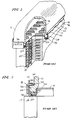
- Figure 1 is a fragmentary perspective view of a conventional heat exchanger assembly utilizing a tank retaining strip made according to the prior art, specifically, according to the aforementioned US-A-4655002 issued February 24, 1987 to Keyzer;
- Figure 2 is an expanded, fragmentary, sectional view of part of the prior art construction;
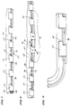
- Figure 3 illustrates a blank utilized in forming a strip made according to the invention;
- Figure 4 is a fragmentary view showing the retaining strip of the invention applied to an otherwise conventional heat exchanger construction such as illustrated in Figure 1;
- Figure 5 is a view similar to Figure 4 but illustrating how the invention prevents improper assembly;
- Figure 6 is a fragmentary, sectional view illustrating the use of a retaining clip according to the invention;
- Figure 7 is a fragmentary, side elevation from the right of Figure 6;
- Figure 8 is a view similar to Figure 5 but of a modified embodiment of the invention;
- Figure 9 is a fragmentary side elevation of the embodiment of Figure 8;
- Figure 10 is a view similar to Figure 8 but of still a further modified embodiment; and
- Figure 11 is a view similar to Figure 9 but of the embodiment of Figure 10.
- Referring first to Figures 1 and 2, the prior art Keyser construction is seen to include a
tank 10 having a peripheral, outwardly extendingflange 11 applied to aheader plate 14. Extending through theheader plate 14 is a plurality ofopen tube ends 16 offlattened tubes 18 which extend in generally parallel relation to each other to another header plate (not shown) and between which serpentine fins 20 extend in a conventional fashion. The body of theheader plate 14 is surrounded by aperipheral groove 22. Thegroove 22 includes aninner wall 24, an upstanding outer wall orflange 26 and abottom 28 defining a seal receiving surface. Located within thegroove 22 is aresilient seal 30 which is compressed against the sealingsurface 28 at the bottom of thegroove 22 by abutment with the sealingsurface 32 on the underside of theperipheral flange 11 of thetank 10. - By compressing the
seal 30, a peripheral seal at the tank to header plate joint is maintained. In order to compress the seal, thetank 10, and specifically, theperipheral flange 11, includes an upper,pressure receiving surface 34 that is opposite thesealing surface 32. - Located about the
upstanding flange 26 is a row of apertures made up ofelongated slots 36. Anelongated retaining strip 38 extends along theupstanding flange 26 as can be best seen in Figure 1 and includes a plurality of inwardly directedfingers 40 that extend into corresponding ones of theslots 36 to overlie and abut thesurface 34 of theflange 11. As a consequence, theflange 11 can be held in compressing relation against theseal 30. - To prevent dissociation of the
strip 38, Keyzer provides deformations or dimples 42 in eachfinger 40 which extend upwardly. Because the resilience of theseal 30 will exert an upward bias against theflange 11 which, in turn, will be applied to each of thefingers 40, thedimples 42 may lodge behind theinnermost surface 44 of theupstanding flange 26 to provide a locking action. - The present invention is directed to a heat exchanger such as a vehicular radiator much like that illustrated in Figures 1 and 2 and described previously herein. According to the invention, however, the
strip 38 and associatedfingers 40 along with thedimples 42 on thefingers 40 of the prior art construction, which can cause the hereinbefore discussed dissociation and assembly problems, are dispensed with in favour of a strip made according to the invention. The remainder of the heat exchanger construction may be the same and in the interest of brevity, will not be described again herein. For clarity, however, the same reference numerals employed in describing the prior art construction other than thestrip 38,fingers 40 anddimples 42 will be used where appropriate. - A tank flange retainer made according to the invention is generally designated 50 and may be stamped from relatively thin sheet metal in the form of a blank shown in Figure 3.
The blank includes an elongated, main body orstrip section 52.Fingers 54 extend from oneedge 56 of thestrip 52 and have opposedsides sides slots 36. - As seen in Fig. 3, the
sides 60 includenotches 62 and theside 64 of eachnotch 62 remote from thestrip 52 is parallel to the direction of elongation of thestrip 52. - The
fingers 54 are bent relative to thestrip 52 by any suitable means generally alonglines 65 to form the retaining strip of the invention. As in the prior art strip, an approximate 90° angle between thefingers 54 and the body of thestrip 52 is utilized. - As seen in Fig. 4, one of the
strips 52 has been applied to theslots 36 in theupstanding flange 26 and brought into overlying relationship and in abutment with theupper surface 34 of theflange 11 to urge the same downwardly thereby compressing theseal 30. As can be seen, thestrip 52 has been shifted somewhat to the right as viewed in Fig. 4 so as to bring thesides 64 of thenotches 62 into a position where they are lodged against theinner surface 44 of theflange 26. In other words, thenotches 62 serve as hook-like formations allowing thefingers 54 to be literally hooked to theflange 26. - To prevent inadvertent dissociation, a wire or plastic clip such as a
ring 66 may be disposed in any one of theslots 36 in abutting relation with theside 58 of thecorresponding finger 54. This will prevent thatfinger 54 from being moved to the left as viewed in Fig. 4 and that in turn will prevent theentire strip 52 from being similarly moved. As a consequence, once assembly has been made and theclip 66 applied, disassembly cannot occur. - This feature of the invention is rather advantageous since, as will be seen, the
clip 66 cannot be applied to the structure unless thestrip 52 is properly installed. This in turn means that an inspector need only look for theclip 66 and observe the same to be assured that there has been proper installation. - Turning now to Fig. 5, it will be appreciated that because the
strip 52 will typically be made from relatively thin metal, it can only be characterized as semi-rigid. Thus, the same may bow as in the general area bracketed at 70 in Fig. 5. If it is attempted to install the strip with thebow 70 intact, thestrip 52 cannot be shifted laterally, here to the right as seen in Fig. 5, to bring thesurfaces 64 of thefingers 54 into a position where they lodge against thesurface 44 of theflange 26. This is due to the fact that what remains of thesides 60 of eachfinger 54 after the formation of thenotch 62 acts as a nose which in turn blocks rightward movement of thecorresponding finger 54, and thus the entire strip. As seen in Fig. 5, two of thefingers 54 have their noses defined by thesides 60 in such blocking relation. Those two fingers are designated A and B. - Thus, the
surfaces 60 define a means that prevent any of thefingers 54 from moving into a lodging or locked position with relation to thesurface 54 of theflange 26 unless all of thefingers 54 move into that position. Only when the latter has occurred can theclip 66 be applied since there will be no space between thesides 58 of thefingers 54 and a corresponding edge of theslots 36 as can be seen in Fig. 5. The noses defined by thesurfaces 60 will block application of theclip 66 to any one of theslots 36 at the opposite end because there is insufficient room through which theclip 66 may pass. - A modified embodiment is illustrated in Figs. 8 and 9 and where like components are employed, like reference numerals will be utilized. This embodiment differs from that just described only in that the
slots 36 are dispensed with in favour ofslots 70 which are in the shape of a flattened L. The total top to bottom length of one of theslots 70 is a little more than twice the thickness of thestrip 38 and the upright leg 72 of eachslot 70 is narrower than thehorizontal leg 74; and the latter is closer to the sealingsurface 28 than the former. - In addition, the length of the
horizontal leg 74 in the direction of elongation of thestrip 38 is slightly greater than the corresponding dimension of thefingers 54 at their maximum dimension. Also, the top to bottom dimension of thehorizontal leg 74 is slightly greater than the thickness of thestrip 38. As a consequence, thefingers 54 may be inserted into theslots 70 through thehorizontal legs 74. - The length of the upstanding leg 72 in the direction of elongation of the
strip 38 is less than that of theleg 74 and is slightly greater than the narrowest dimension of thefingers 54. Thus, once thefingers 54 have been inserted through thehorizontal leg 74, thestrip 38 may be shifted to the right as viewed in Fig. 9 and then the fingers shifted upwardly into theupstanding leg 70 and moved from the hatched position to the solid line position illustrated in Fig. 9. As a consequence, thatside 76 of the finger opposite from the hook will abut an edge 78 of the upstanding leg 72 while being locked in place such that it cannot be dislodged. If desired, the L-shapedapertures 70 may be utilized along the entire length of the flange but it is only necessary that they be utilized at one location for eachstrip 38. Thus, as shown in Fig. 9, anadjacent aperture 80 is shaped as theapertures 36 but has increased top to bottom dimension so as to allow the shifting of the fingers as mentioned previously. - In this embodiment, the resiliency of the
seal 30 is utilized to retain the fingers in the upper part of theapertures tank 10 is caused to compress theseal 30 sufficiently so that thefingers 54 may be caused to enter theapertures seal 30 will urge the sealingsurface 32 of theflange 44 upwardly as viewed in Figs. 8 and 9. Theflange 44 will in turn act against thefingers 54 to hold them in the desired position. - Figs. 10 and 11 show still another embodiment of the invention. This embodiment also makes use of the resiliency of the
seal 30. According to this embodiment of the invention,trapezoidal apertures 90 are utilized and have theirmajor bases 92 downwardly and theirminor bases 94 remote from thesurface 28. According to this embodiment of the invention, the hook-like formations are T-shaped as shown at 96 and have oppositely directednoses 98 extending from the base of thefinger 100. - According to this embodiment of the invention, the
apertures 90 have a top to bottom dimension that is on the order of twice the thickness of thestrip 38 and at a location midway between thebases nose 98 to the other on a given hook-like formation 96. Consequently, the fingers may be inserted into theapertures 90 adjacent thebase 92 and allowed to move upwardly within theapertures 90 as a result of the resiliency of theseal 30. When such occurs, as can be seen in Fig. 11, thenoses 98 are lodged behind part of the flange for retaining purposes. One advantage of the embodiment of Figs. 10 and 11 is that one need only insert thefingers 100 into theapertures 90 and allow the resiliency of theseal 30 to takeover. That is to say, there is no need to provide a lateral shifting of thestrip 38 as is necessary with the prior embodiments. - It will accordingly be appreciated that an improved retaining strip made according to the invention retains all of the advantages of the prior art strip of Keyzer in terms of being usable and providing a releasable but readily sealed tank to header plate connection for a heat exchanger. At the same time, the disadvantages associated with the possibility of improper assembly and/or improper handling have been eliminated.
Claims (15)
- A heat exchanger comprising a header plate (14) having a peripheral seal receiving groove (22), a resilient seal (30) disposed in the groove (22), an upstanding flange (26) surrounding the groove (22), an aligned row of apertures (36; 70; 80; 90) in the flange (26) above the bottom of the groove (22), a tank (10) having a peripheral outwardly directed flange (11) located in the groove (22) and having a first surface (32) sealed against and compressing the seal (30) and an opposed surface (34) nominally aligned with the row of apertures (36; 70; 80; 90), and a tank flange retainer (50) including an elongated strip (52; 38) with a plurality of formations (54; 96) disposed on the side of the upstanding flange (26) opposite the groove (22) with the formations (54; 96) extending through the apertures (36; 70; 80; 90) and oppositely of the strip (52; 38) in overlying relation to the tank flange (11) to engage the opposed surface (34) of the tank flange (11), characterized in that each of the formations (54; 96) is hook-like with the hook-part (60; 98) of the hook-like formation (54; 96) lodged against a side of the upstanding flange (26) oppositely of the strip (52; 38).
- A heat exchanger as claimed in claim 1, wherein each of the hook-like formations (54; 96) includes a nose (60; 98), and all of the noses (60; 98) extend in the direction of elongation of the strip (52; 38).
- A heat exchanger as claimed in claim 1 or claim 2, further including a clip (66) in one (36) of said apertures (36) and abutting the corresponding hook-like formation (54) to prevent the same from moving appreciably in said one aperture (36) thereby preventing the strip (52) from moving appreciably relative to the upstanding flange (26).
- A heat exchanger as claimed in claim 1 or claim 2, wherein the apertures (90) are narrower at their location farthest from the groove (22) than at their location nearest the groove (22).
- A heat exchanger as claimed in claim 4, wherein the dimension of each hook-like formation (96) in the direction of elongation of the strip (38) is less than the dimension of the corresponding aperture (90) at said nearest location and greater than the dimension of the corresponding aperture (90) at said farthest location.
- A heat exchanger as claimed in claim 4 or claim 5, wherein the hook-like formations (96) are T-shaped.
- A heat exchanger as claimed in claim 1, wherein the hook-like formations (54; 96) are defined by a plurality of fingers (54; 100) terminating in hook-like noses (60; 98) which are located on the side of the upstanding flange (26) opposite the groove (22) with the fingers (54; 100) extending through the apertures (30; 70; 80; 90) such that the noses (60; 98) lodge against the upstanding flange (26) oppositely of the strip (52; 38) in overlying relation to the tank flange (11) and in engagement with the opposed surface of the tank flange (11).
- A heat exchanger as claimed in claim 7, wherein the apertures (70; 90) are relatively narrow remote from the opposed surface (34) of the upstanding flange (26) and relatively wide close to that surface (34), and the hook-like noses (60; 98) are sized so as to be movable into and out of the apertures (70; 90) close to the surface (34) but captured in the apertures (70; 90) when remote from the surface (34), the resilient seal (30) urging the tank (10) away from the surface (34) such that the tank flange (11) urges the noses (60; 98) into the narrow part of the corresponding aperture (70; 90).
- A heat exchanger as claimed in claim 8, wherein the noses (98) extend oppositely from both sides of the finger (100).
- A heat exchanger as claimed in claim 9, wherein the apertures (90) are trapezoidal.
- A heat exchanger as claimed in claim 8, wherein the apertures (70) are L-shaped.
- A heat exchanger as claimed in claim 1, further including means (60) on the strip (38; 52) for preventing any of the hook-like formations (54) from lodging against the upstanding flange (26) unless all of the hook-like formations (54) lodge against the upstanding flange (26).
- A heat exchanger as claimed in claim 12, wherein the hook-like formations (54) all open in the same direction of elongation of the strip (38; 52) and the preventing means (60) comprise noses (60) on the hook-like formations (54).
- A heat exchanger as claimed in claim 13, wherein the hook-like formations (54) are formed by notches (62) in fingers (54) extending generally transversely from the strip (38; 52).
- A heat-exchanger as claimed in claim 14, wherein the apertures (36; 70; 80) are slots (36; 70; 80) elongated in the direction of elongation of the strip (52; 38) and having a length slightly greater than the width of the fingers (54) at the noses (60).
Priority Applications (1)
| Application Number | Priority Date | Filing Date | Title |
|---|---|---|---|
| AT89313716T ATE102703T1 (en) | 1989-02-23 | 1989-12-29 | DEVICE FOR SUPPORTING A TANK FOR HEAT EXCHANGER. |
Applications Claiming Priority (2)
| Application Number | Priority Date | Filing Date | Title |
|---|---|---|---|
| US314157 | 1989-02-23 | ||
| US07/314,157 US4899815A (en) | 1989-02-23 | 1989-02-23 | Tank retaining strip for heat exchangers |
Publications (2)
| Publication Number | Publication Date |
|---|---|
| EP0384085A1 EP0384085A1 (en) | 1990-08-29 |
| EP0384085B1 true EP0384085B1 (en) | 1994-03-09 |
Family
ID=23218810
Family Applications (1)
| Application Number | Title | Priority Date | Filing Date |
|---|---|---|---|
| EP89313716A Expired - Lifetime EP0384085B1 (en) | 1989-02-23 | 1989-12-29 | Improved tank retaining strip for heat exchangers |
Country Status (12)
| Country | Link |
|---|---|
| US (1) | US4899815A (en) |
| EP (1) | EP0384085B1 (en) |
| JP (1) | JP2754075B2 (en) |
| KR (2) | KR900013280A (en) |
| AR (1) | AR244878A1 (en) |
| AT (1) | ATE102703T1 (en) |
| AU (1) | AU612310B2 (en) |
| BR (1) | BR9000529A (en) |
| CA (1) | CA2006864C (en) |
| DE (1) | DE68913718T2 (en) |
| ES (1) | ES2052035T3 (en) |
| MX (1) | MX165311B (en) |
Families Citing this family (14)
| Publication number | Priority date | Publication date | Assignee | Title |
|---|---|---|---|---|
| DE4313141C2 (en) * | 1993-04-22 | 1995-04-13 | Voith Gmbh J M | Flange driver for a universal joint |
| FR2732454B1 (en) * | 1995-03-27 | 1997-05-09 | Valeo Thermique Moteur Sa | HEAT EXCHANGER, ESPECIALLY FOR A MOTOR VEHICLE |
| FR2735857B1 (en) * | 1995-06-20 | 1997-08-01 | Valeo Climatisation | HEAT EXCHANGER, ESPECIALLY FOR A MOTOR VEHICLE |
| FR2742530B1 (en) * | 1995-12-13 | 1998-01-30 | Valeo Thermique Moteur Sa | DEVICE AND METHOD FOR ASSEMBLING A COLLECTOR PLATE AND A HEAT EXCHANGER WATER BOX |
| DE19935688B4 (en) * | 1999-07-29 | 2004-07-01 | Behr Gmbh & Co. | Heat exchanger, in particular for motor vehicles |
| US6675883B1 (en) * | 2002-07-08 | 2004-01-13 | Modine Manufacturing Company | Manifold for heat exchanger |
| DE10250441A1 (en) * | 2002-10-30 | 2004-05-13 | Modine Manufacturing Co., Racine | Heat exchanger with seal has molding to fit in corresponding through aperture and at least one marker at edge of tube bottom |
| DE102014204272A1 (en) * | 2013-04-25 | 2014-10-30 | MAHLE Behr GmbH & Co. KG | Heat exchanger |
| DE102013225326A1 (en) * | 2013-12-09 | 2015-06-11 | MAHLE Behr GmbH & Co. KG | Heat exchanger |
| US10337801B2 (en) * | 2013-12-20 | 2019-07-02 | Modine Manufacturing Company | Heat exchanger for cooling a flow of charge air, and method of assembling the same |
| DE102014219210A1 (en) * | 2014-09-22 | 2016-03-24 | Mahle International Gmbh | Heat exchanger |
| WO2017049609A1 (en) * | 2015-09-25 | 2017-03-30 | Trane Air Conditioning Systems (China) Co., Ltd. | Fixing device for heat exchanger |
| US10527364B2 (en) * | 2017-03-03 | 2020-01-07 | Enterex America LLC | Heat exchanger manifold with header groove reinforcement member |
| WO2020166903A1 (en) * | 2019-02-11 | 2020-08-20 | 한온시스템 주식회사 | Cooling module |
Family Cites Families (16)
| Publication number | Priority date | Publication date | Assignee | Title |
|---|---|---|---|---|
| US3352584A (en) * | 1964-12-16 | 1967-11-14 | Redirack Ind Ltd | Locking pin device for pallet rack |
| DE2703528C3 (en) * | 1977-01-28 | 1982-03-11 | Kühlerfabrik Längerer & Reich, 7024 Filderstadt | Water cooler, especially for an internal combustion engine |
| JPS5923991Y2 (en) * | 1979-03-13 | 1984-07-16 | 日本ラヂエーター株式会社 | Heat exchanger |
| US4287994A (en) * | 1979-11-02 | 1981-09-08 | Unarco Industries, Inc. | Wedgable storage rack |
| FR2469686A1 (en) * | 1979-11-12 | 1981-05-22 | Chausson Usines Sa | HEAT EXCHANGER COMPRISING A BEAM OF TUBES OPENING INTO COLLECTOR PLATES MECHANICALLY CONNECTED TO WATER BOXES |
| US4351390A (en) * | 1980-02-11 | 1982-09-28 | Borg-Warner Corporation | Retaining clips for gasketed tanks on heat exchangers |
| JPS587092U (en) * | 1981-07-02 | 1983-01-18 | 株式会社デンソー | Heat exchanger |
| US4406374A (en) * | 1981-08-12 | 1983-09-27 | Myco, Inc. | Locking device for display rack |
| JPS5877288U (en) * | 1981-11-13 | 1983-05-25 | カルソニックカンセイ株式会社 | Heater core of automotive air conditioner |
| US4485867A (en) * | 1982-02-08 | 1984-12-04 | Ex-Cell-O Corporation | Heat exchanger |
| SU1052834A1 (en) * | 1982-07-22 | 1983-11-07 | Производственное Объединение "Радиатор" | Radiator tank |
| SE437648B (en) * | 1983-04-15 | 1985-03-11 | Electrolux Const Ab | DEVICE FOR LOADING A BALK BY A POST, EXV WITH A Pallet Rack |
| FR2550328B1 (en) * | 1983-08-04 | 1989-01-13 | Chausson Usines Sa | CONNECTION DEVICE BETWEEN A COLLECTOR PLATE AND A WATER BOX OF A HEAT EXCHANGER AND METHOD FOR ITS IMPLEMENTATION |
| NL8303966A (en) * | 1983-11-17 | 1985-06-17 | Nrf Holding | RADIATOR. |
| US4546823A (en) * | 1985-02-11 | 1985-10-15 | Mccord Heat Transfer Corporation | Solderless radiator |
| US4682672A (en) * | 1986-04-21 | 1987-07-28 | Ford Motor Company | Snap-on oil pan |
-
1989
- 1989-02-23 US US07/314,157 patent/US4899815A/en not_active Expired - Fee Related
- 1989-12-28 CA CA002006864A patent/CA2006864C/en not_active Expired - Fee Related
- 1989-12-29 AT AT89313716T patent/ATE102703T1/en not_active IP Right Cessation
- 1989-12-29 EP EP89313716A patent/EP0384085B1/en not_active Expired - Lifetime
- 1989-12-29 ES ES89313716T patent/ES2052035T3/en not_active Expired - Lifetime
- 1989-12-29 DE DE68913718T patent/DE68913718T2/en not_active Expired - Fee Related
-
1990
- 1990-01-08 AU AU47784/90A patent/AU612310B2/en not_active Ceased
- 1990-01-18 KR KR1019900000564A patent/KR900013280A/en not_active Withdrawn
- 1990-01-26 MX MX019266A patent/MX165311B/en unknown
- 1990-02-07 BR BR909000529A patent/BR9000529A/en not_active IP Right Cessation
- 1990-02-21 KR KR2019900001907U patent/KR0125082Y1/en not_active Expired - Fee Related
- 1990-02-22 JP JP2039912A patent/JP2754075B2/en not_active Expired - Lifetime
- 1990-02-23 AR AR90316241A patent/AR244878A1/en active
Also Published As
| Publication number | Publication date |
|---|---|
| KR910015800U (en) | 1991-09-25 |
| DE68913718T2 (en) | 1994-06-23 |
| MX165311B (en) | 1992-11-04 |
| AR244878A1 (en) | 1993-11-30 |
| JP2754075B2 (en) | 1998-05-20 |
| EP0384085A1 (en) | 1990-08-29 |
| KR900013280A (en) | 1990-09-05 |
| CA2006864C (en) | 1999-07-20 |
| AU612310B2 (en) | 1991-07-04 |
| BR9000529A (en) | 1991-01-15 |
| AU4778490A (en) | 1990-08-30 |
| ES2052035T3 (en) | 1994-07-01 |
| US4899815A (en) | 1990-02-13 |
| KR0125082Y1 (en) | 1998-11-02 |
| JPH02267494A (en) | 1990-11-01 |
| CA2006864A1 (en) | 1990-08-23 |
| DE68913718D1 (en) | 1994-04-14 |
| ATE102703T1 (en) | 1994-03-15 |
Similar Documents
| Publication | Publication Date | Title |
|---|---|---|
| US4899815A (en) | Tank retaining strip for heat exchangers | |
| CA2052877C (en) | Double plate partition for a heat exchanger | |
| US5101887A (en) | Heat exchanger | |
| AU754417B2 (en) | Welded heat exchanger with grommet construction | |
| US5314021A (en) | Heat exchanger with a plurality of ranges of tubes, in particular for a motor vehicle | |
| US5758721A (en) | Heat exchanger header plate, a method for making it, and a heat exchanger having such a header plate | |
| US5402571A (en) | Method of making a heat exchanger | |
| CN109844441B (en) | Heat Exchanger with Bypass Seal with Retaining Clip | |
| EP0625679A1 (en) | Cooling unit and drain case for air conditioners | |
| RU2225580C2 (en) | Plate type heat exchanger and plate member for it | |
| US7237605B2 (en) | Heat exchanger | |
| EP0745820A1 (en) | Header of heat exchanger | |
| CN101111736B (en) | Heat exchanger | |
| US5058662A (en) | Multi tube heat exchanger with integral tube spacers and interlocks | |
| EP0724128A1 (en) | Heat exchanger tank to be mounted in a heat exchanger and method of producing it | |
| JP2020526731A (en) | Heat exchanger | |
| US5899267A (en) | Heat exchanger sealed tank and header assembly with gasket displacement prevention | |
| US7520319B2 (en) | Stacking-type, multi-flow, heat exchanger | |
| US5363911A (en) | Two-part tubular wall, and a method for making a motor vehicle air conditioning condenser having such a tubular wall | |
| US6182745B1 (en) | Heat exchanger with protected thin edges, especially for a motor vehicle | |
| US5404940A (en) | Tie bar clip construction for heat exchangers | |
| JP2573421Y2 (en) | Heat exchanger | |
| JP3173830B2 (en) | Heat exchanger | |
| JP2003130580A (en) | Tank structure of heat exchanger | |
| JPH11311489A (en) | Heat exchanger fins |
Legal Events
| Date | Code | Title | Description |
|---|---|---|---|
| PUAI | Public reference made under article 153(3) epc to a published international application that has entered the european phase |
Free format text: ORIGINAL CODE: 0009012 |
|
| AK | Designated contracting states |
Kind code of ref document: A1 Designated state(s): AT DE ES FR GB IT NL SE |
|
| 17P | Request for examination filed |
Effective date: 19901003 |
|
| 17Q | First examination report despatched |
Effective date: 19910325 |
|
| GRAA | (expected) grant |
Free format text: ORIGINAL CODE: 0009210 |
|
| AK | Designated contracting states |
Kind code of ref document: B1 Designated state(s): AT DE ES FR GB IT NL SE |
|
| ITF | It: translation for a ep patent filed | ||
| REF | Corresponds to: |
Ref document number: 102703 Country of ref document: AT Date of ref document: 19940315 Kind code of ref document: T |
|
| REF | Corresponds to: |
Ref document number: 68913718 Country of ref document: DE Date of ref document: 19940414 |
|
| REG | Reference to a national code |
Ref country code: ES Ref legal event code: FG2A Ref document number: 2052035 Country of ref document: ES Kind code of ref document: T3 |
|
| ET | Fr: translation filed | ||
| PLBE | No opposition filed within time limit |
Free format text: ORIGINAL CODE: 0009261 |
|
| STAA | Information on the status of an ep patent application or granted ep patent |
Free format text: STATUS: NO OPPOSITION FILED WITHIN TIME LIMIT |
|
| EAL | Se: european patent in force in sweden |
Ref document number: 89313716.6 |
|
| 26N | No opposition filed | ||
| PGFP | Annual fee paid to national office [announced via postgrant information from national office to epo] |
Ref country code: NL Payment date: 20001130 Year of fee payment: 12 Ref country code: FR Payment date: 20001130 Year of fee payment: 12 |
|
| PGFP | Annual fee paid to national office [announced via postgrant information from national office to epo] |
Ref country code: SE Payment date: 20001201 Year of fee payment: 12 Ref country code: GB Payment date: 20001201 Year of fee payment: 12 |
|
| PGFP | Annual fee paid to national office [announced via postgrant information from national office to epo] |
Ref country code: AT Payment date: 20001204 Year of fee payment: 12 |
|
| PGFP | Annual fee paid to national office [announced via postgrant information from national office to epo] |
Ref country code: DE Payment date: 20001211 Year of fee payment: 12 |
|
| PGFP | Annual fee paid to national office [announced via postgrant information from national office to epo] |
Ref country code: ES Payment date: 20010112 Year of fee payment: 12 |
|
| PG25 | Lapsed in a contracting state [announced via postgrant information from national office to epo] |
Ref country code: GB Free format text: LAPSE BECAUSE OF NON-PAYMENT OF DUE FEES Effective date: 20011229 Ref country code: AT Free format text: LAPSE BECAUSE OF NON-PAYMENT OF DUE FEES Effective date: 20011229 |
|
| PG25 | Lapsed in a contracting state [announced via postgrant information from national office to epo] |
Ref country code: SE Free format text: LAPSE BECAUSE OF NON-PAYMENT OF DUE FEES Effective date: 20011230 |
|
| REG | Reference to a national code |
Ref country code: GB Ref legal event code: IF02 |
|
| PG25 | Lapsed in a contracting state [announced via postgrant information from national office to epo] |
Ref country code: NL Free format text: LAPSE BECAUSE OF NON-PAYMENT OF DUE FEES Effective date: 20020701 |
|
| PG25 | Lapsed in a contracting state [announced via postgrant information from national office to epo] |
Ref country code: DE Free format text: LAPSE BECAUSE OF NON-PAYMENT OF DUE FEES Effective date: 20020702 |
|
| EUG | Se: european patent has lapsed |
Ref document number: 89313716.6 |
|
| GBPC | Gb: european patent ceased through non-payment of renewal fee |
Effective date: 20011229 |
|
| PG25 | Lapsed in a contracting state [announced via postgrant information from national office to epo] |
Ref country code: FR Free format text: LAPSE BECAUSE OF NON-PAYMENT OF DUE FEES Effective date: 20020830 |
|
| NLV4 | Nl: lapsed or anulled due to non-payment of the annual fee |
Effective date: 20020701 |
|
| REG | Reference to a national code |
Ref country code: FR Ref legal event code: ST |
|
| PG25 | Lapsed in a contracting state [announced via postgrant information from national office to epo] |
Ref country code: ES Free format text: LAPSE BECAUSE OF NON-PAYMENT OF DUE FEES Effective date: 20021230 |
|
| REG | Reference to a national code |
Ref country code: ES Ref legal event code: FD2A Effective date: 20030113 |
|
| PG25 | Lapsed in a contracting state [announced via postgrant information from national office to epo] |
Ref country code: IT Free format text: LAPSE BECAUSE OF NON-PAYMENT OF DUE FEES;WARNING: LAPSES OF ITALIAN PATENTS WITH EFFECTIVE DATE BEFORE 2007 MAY HAVE OCCURRED AT ANY TIME BEFORE 2007. THE CORRECT EFFECTIVE DATE MAY BE DIFFERENT FROM THE ONE RECORDED. Effective date: 20051229 |