EP0383884B1 - Clamping ring - Google Patents
Clamping ring Download PDFInfo
- Publication number
- EP0383884B1 EP0383884B1 EP19890909252 EP89909252A EP0383884B1 EP 0383884 B1 EP0383884 B1 EP 0383884B1 EP 19890909252 EP19890909252 EP 19890909252 EP 89909252 A EP89909252 A EP 89909252A EP 0383884 B1 EP0383884 B1 EP 0383884B1
- Authority
- EP
- European Patent Office
- Prior art keywords
- clamping ring
- clamping
- end portions
- draining gutter
- spring
- Prior art date
- Legal status (The legal status is an assumption and is not a legal conclusion. Google has not performed a legal analysis and makes no representation as to the accuracy of the status listed.)
- Expired
Links
- 239000000463 material Substances 0.000 claims abstract description 41
- 230000000916 dilatatory effect Effects 0.000 claims abstract 2
- 210000000078 claw Anatomy 0.000 claims description 4
- 230000005923 long-lasting effect Effects 0.000 abstract 1
- 229910000639 Spring steel Inorganic materials 0.000 description 2
- 230000006835 compression Effects 0.000 description 2
- 238000007906 compression Methods 0.000 description 2
- 230000000149 penetrating effect Effects 0.000 description 2
- 230000002093 peripheral effect Effects 0.000 description 2
- XLYOFNOQVPJJNP-UHFFFAOYSA-N water Substances O XLYOFNOQVPJJNP-UHFFFAOYSA-N 0.000 description 2
- 239000012535 impurity Substances 0.000 description 1
- 239000012858 resilient material Substances 0.000 description 1
- 238000007789 sealing Methods 0.000 description 1
- 238000000926 separation method Methods 0.000 description 1
Images
Classifications
-
- E—FIXED CONSTRUCTIONS
- E02—HYDRAULIC ENGINEERING; FOUNDATIONS; SOIL SHIFTING
- E02D—FOUNDATIONS; EXCAVATIONS; EMBANKMENTS; UNDERGROUND OR UNDERWATER STRUCTURES
- E02D29/00—Independent underground or underwater structures; Retaining walls
- E02D29/12—Manhole shafts; Other inspection or access chambers; Accessories therefor
- E02D29/14—Covers for manholes or the like; Frames for covers
- E02D29/1427—Locking devices
-
- E—FIXED CONSTRUCTIONS
- E03—WATER SUPPLY; SEWERAGE
- E03F—SEWERS; CESSPOOLS
- E03F5/00—Sewerage structures
- E03F5/04—Gullies inlets, road sinks, floor drains with or without odour seals or sediment traps
- E03F5/06—Gully gratings
-
- E—FIXED CONSTRUCTIONS
- E04—BUILDING
- E04D—ROOF COVERINGS; SKY-LIGHTS; GUTTERS; ROOF-WORKING TOOLS
- E04D13/00—Special arrangements or devices in connection with roof coverings; Protection against birds; Roof drainage ; Sky-lights
- E04D13/04—Roof drainage; Drainage fittings in flat roofs, balconies or the like
- E04D13/0404—Drainage on the roof surface
- E04D13/0409—Drainage outlets, e.g. gullies
-
- E—FIXED CONSTRUCTIONS
- E03—WATER SUPPLY; SEWERAGE
- E03F—SEWERS; CESSPOOLS
- E03F5/00—Sewerage structures
- E03F5/04—Gullies inlets, road sinks, floor drains with or without odour seals or sediment traps
- E03F5/06—Gully gratings
- E03F2005/065—Gully gratings with elastic locking elements
-
- E—FIXED CONSTRUCTIONS
- E04—BUILDING
- E04D—ROOF COVERINGS; SKY-LIGHTS; GUTTERS; ROOF-WORKING TOOLS
- E04D13/00—Special arrangements or devices in connection with roof coverings; Protection against birds; Roof drainage ; Sky-lights
- E04D13/04—Roof drainage; Drainage fittings in flat roofs, balconies or the like
- E04D13/0404—Drainage on the roof surface
- E04D13/0409—Drainage outlets, e.g. gullies
- E04D2013/0436—Drainage outlets, e.g. gullies with sealing means
Definitions
- the present invention relates to a clamping ring for clamping covering materials, preferably floor covering materials against the inner side of a draining gutter, preferably a draining gutter adapted to be mounted in a floor, whereby the clamping ring is split and compressible in radial direction against the action of a spring force which is provided, after mounting the clamping ring in the draining gutter, to dilate said clamping ring in radial direction until it engages the covering material and clamps said material against the inner side of the draining gutter.
- Clamping rings of the above type are already known from e.g. patent specification CH-A-461 391.
- the spring force in this clamping ring is generated while the clamping ring is made of a resilient material permitting it, after radial compression, to dilate or expand with sufficient force for efficient clamping of the covering material against the inner side of the gutter. Since it is the material in the clamping ring which is utilized to generate the spring force, it is necessary to design the clamping ring with varying width if it shall provide the same pressure all around and simultaneously maintain its circular shape.
- a clamping ring with a "resilient slit” is previously known from Patent specification SE-B-306 062 (fig. 8), but this clamping ring is not split but has a folded portion which possibly might serve as a type of clamping portion. Since this portion however, is not as high as the remaining parts of the ring and forms only a very small section of the ring, said ring is either hard to tighten or does not provide sufficient tensional force.
- the object of the present invention is to eliminate the problems at clamping rings of the prior art type and provide a clamping ring which is easy to stretch, which provides sufficient tensional force within the required interval for clamping either thin or thick floor covering materials, which excludes the risks for too powerful a dilatation and which ensures as good a sealing around the entire periphery thereof.
- the clamping rings 1, 2 and 3 illustrated in the drawings are adapted to be used for clamping a covering material, preferably a floor covering material 4 against the inner side 5 of a drainage gutter, preferably a drainage gutter 6 to be mounted in a floor.
- the floor covering material 4 is folded down into the inlet portion of the drainage gutter and the purpose with the clamping of the covering material 4 is to prevent damages by water penetrating under the covering material.
- the clamping ring 1, 2 or 3 shown is split at one point and compressible against the action of a spring force which is adapted, after mounting the clamping ring in the drainage gutter 6, to dilate said clamping ring in radial direction until it engages the floor covering material 4 and clamps it against the inner side 5.
- the spring force is generated by a spring means, preferably a helical spring 7, which is mounted between two end portions 8, 9 of the clamping ring.
- This helical spring 7 is stretchable by pressing the end portions 8, 9 peripherically (arrows A in fig. 4) towards each other.
- the end portions 8, 9 are designed such that they together form an unbroken outer periphery at the parting area 10 of the clamping ring.
- said end portions 8, 9 are not brought apart so far that the helical spring 7 falls out of its position therebetween, said end portions are provided with lock surfaces 11, 12 which are adapted to engage each other and thereby prevent further separation.
- the helical spring 7 is preferably guided along a part of its length by engaging holes 13, 14 in the end portions 8, 9.
- the holes 13, 14 extend a distance into the end portions 8, 9 and run therealong in peripheral direction.
- the helical spring 7 extends through a space 15 between the end portions 8, 9, which space is closed at least at the upper side 16 of the clamping ring 1, 2 or 3 and at the inner side 17 of said ring in order to prevent impurities from penetrating into said space and counteract the function of the helical spring or give rise to other problems.
- the helical spring 7 is preferably made of spring steel and its outer diameter preferably exceeds half the width of the clamping ring 1, 2 or 3. Furthermore, the outer diameter of the helical spring 7 is equivalent to six times its size of wire. A helical spring sized in this manner has been shown to be especially advantageous regarding sufficient tensional force and the required springing distance.
- the helical spring 7 is also dimensioned such that it generates sufficient tensional force to efficiently clamp covering material 4 with a thickness of 1,5 - 2,5 mm against the inner side 5 of the draining gutter 6.
- the end portions 8, 9 of the clamping ring 1, 2 or 3 preferably include peripherically directed guide portions 18, 19 which are designed to guide each other during compression or dilatation of the clamping ring.
- the guide portions 18, 19 extend peripherically and one guide portion 19 has a substantially L-shaped profile in order to define an inner shank 20 and an upper shank 21.
- the inner shank 20 cooperates with an inner guide surface 22 on the other guide portion 18 and defines an inner wall which shields the space 15 from the area 23 radially, within the clamping ring 1.
- the upper shank 21 cooperates with an upper guide surface 24 on the other guide portion 18 and defines a roof for said space 15.
- the guide portion 18 preferably has a groove 25 and the guide portion 19 a tongue inserted into said groove in order to ensure that the guide portions 18, 19 maintain their cooperation with each other.
- a peripheral longitudinal groove 27 with an end edge that defines the lock surface 12 of one end portion 8, while the lock surface 11 of the other end portion 9 is defined by a claw 28 extending into the groove 27.
- the outer side 29 of the clamping ring 1 has an engaging point 30 extending peripherically around the clamping ring and extending unbroken also at the end portions 8, 9 and through which said outer side engages the floor covering material 4.
- the holes 13, 14 for the helical spring 7 may be open towards the outer side 29 of the clamping ring 1 such that said spring may reach out through these openings 31, 32.
- the helical spring 7 may directly engage the floor covering material 4 and affect it directly.
- the clamping ring 1, 2 or 3 is preferably made such that it - before the helical spring 7 is mounted and the end portions brought in contact with each other - has an original shape wherein the end portions overlap each other to such an extent (measure C in fig. 6) that the clamping ring in its original shape has an outer diameter D lying between the diameter of the draining gutter 6 within the floor covering material 4 if said gutter has a covering material with a certain thickness, and the diameter of the draining gutter within the floor covering material if the gutter is provided with a covering material with a lesser thickness.
- the clamping ring 2 shown in figures 7-9 differs from the clamping ring 1 only in a somewhat different shape of the end portions 8, 9.
- one of the end portions 9 has a substantially U-shaped profile, while the other end portion 8 has a planar profile and is adapted to engage the firstmentioned end portion 9.
- one of the end portions 9 also has a U-shaped profile, while the other end portion 8 has a planar profile.
- This clamping ring 3 differs from the clamping ring 2 in that e.g. only the end portion 9 has a peripherically extending hole 14 into which the helical spring 7 protrudes.
- the other end of the helical spring 7 is here engaging the end surface 33 of the other end portion 8 instead of protruding into a hole also in this end portion 8.
- the clamping ring 1, 2 or 3 is mounted preferably by inserting it into the draining gutter 6 in an inclined position until the portion transverse to the end portions 8, 9 engages the floor covering material 4 while one hold on to the end portions 8, 9 above the draining gutter. In this way, one can lean against the draining gutter 6 when one presses the end portions 8, 9 towards each other and thus stretches the helical spring 7.
- the end portions 8, 9 are pressed towards each other until the outer diameter of the clamping ring 1, 2 or 3 is less than the inner diameter of the draining gutter 6, within the floor covering material 4, whereafter the rest of the clamping ring 1 is brought to the intended position in the draining gutter.
- the clamping ring 1, 2 or 3 is released, whereby the helical spring 7 will expand said ring until it engages the floor covering material 4 around the entire periphery thereof.
- the mounting of the clamping ring 1, 2 or 3 is thus finished and it will maintain its pressure against the floor covering material 4 even if it should shrink since then the helical spring 7 will expand or dilate the clamping ring correspondingly.
- the clamping ring can be made of plastic or another suitable material and that is preferably is resilient; the clamping ring may be split at more than one location; the helical spring may be of another type of spring means mounted between the end portions; the spring means can be made of spring steel which is preferably stainless or of another suitable material; more than one spring means may be mounted between the end portions; the lock surfaces may be formed in another way than shown; the draining gutter may be adapted to be mounted in floors and include water traps or not, or may be another type of draining gutter and the covering material may be of another type than floor covering material, e.g. roof covering material if the draining gutter is adapted for roofs.
Landscapes
- Engineering & Computer Science (AREA)
- Civil Engineering (AREA)
- Life Sciences & Earth Sciences (AREA)
- Structural Engineering (AREA)
- Public Health (AREA)
- Mining & Mineral Resources (AREA)
- Architecture (AREA)
- Health & Medical Sciences (AREA)
- Hydrology & Water Resources (AREA)
- Environmental & Geological Engineering (AREA)
- General Life Sciences & Earth Sciences (AREA)
- Water Supply & Treatment (AREA)
- Paleontology (AREA)
- General Engineering & Computer Science (AREA)
- Clamps And Clips (AREA)
- Building Environments (AREA)
- Springs (AREA)
- Sink And Installation For Waste Water (AREA)
- Floor Finish (AREA)
Abstract
Description
- The present invention relates to a clamping ring for clamping covering materials, preferably floor covering materials against the inner side of a draining gutter, preferably a draining gutter adapted to be mounted in a floor, whereby the clamping ring is split and compressible in radial direction against the action of a spring force which is provided, after mounting the clamping ring in the draining gutter, to dilate said clamping ring in radial direction until it engages the covering material and clamps said material against the inner side of the draining gutter.
- Clamping rings of the above type are already known from e.g. patent specification CH-A-461 391. The spring force in this clamping ring is generated while the clamping ring is made of a resilient material permitting it, after radial compression, to dilate or expand with sufficient force for efficient clamping of the covering material against the inner side of the gutter. Since it is the material in the clamping ring which is utilized to generate the spring force, it is necessary to design the clamping ring with varying width if it shall provide the same pressure all around and simultaneously maintain its circular shape.
- However, a problem arise if the clamping ring is given varying width, because the tensional force of its narrower portions diminish more rapidly than its thicker portions. This is of course inappropriate since it is important that the clamping ring has the same clamping or tensional force all around also after a few years of use.
- A clamping ring with a "resilient slit" is previously known from Patent specification SE-B-306 062 (fig. 8), but this clamping ring is not split but has a folded portion which possibly might serve as a type of clamping portion. Since this portion however, is not as high as the remaining parts of the ring and forms only a very small section of the ring, said ring is either hard to tighten or does not provide sufficient tensional force.
- The object of the present invention is to eliminate the problems at clamping rings of the prior art type and provide a clamping ring which is easy to stretch, which provides sufficient tensional force within the required interval for clamping either thin or thick floor covering materials, which excludes the risks for too powerful a dilatation and which ensures as good a sealing around the entire periphery thereof. This is arrived at while the abovementioned clamping ring has been given the characterizing features of
subsequent claim 1. - The invention will be described in more detail below with reference to the accompanying drawings, in which
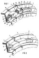
- figure 1 is a perspective view of a part of a clamping ring of the invention disposed in the inlet portion of a draining gutter, whereby some portions of the clamping ring are cut away;
- figure 2 is similar to figure 1, but with the clamping ring uncut;
- figure 3 is a side view of the clamping ring of figure 1;
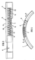
- figure 4 is a plan view of a portion of the clamping ring of figure 1 in radially compressed condition;
- figure 5 is similar to figure 4 but with the clamping ring stretched;
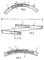
- figure 6 is a side view of the clamping ring of figure 1 before bringing together its end portions;
- figure 7 is a plan view, partly in section, of a portion of an alternatively designed clamping ring;
- figure 8 illustrates a portion of the clamping ring of figure 7 seen from the centre of said ring;
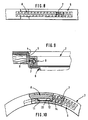
- figure 9 is a section through the clamping ring of figure 7 when disposed in a drainage gutter; and
- figure 10 finally, is a plan view of a portion of a second alternatively designed clamping ring.
- The
clamping rings inner side 5 of a drainage gutter, preferably adrainage gutter 6 to be mounted in a floor. The floor covering material 4 is folded down into the inlet portion of the drainage gutter and the purpose with the clamping of the covering material 4 is to prevent damages by water penetrating under the covering material. - The
clamping ring drainage gutter 6, to dilate said clamping ring in radial direction until it engages the floor covering material 4 and clamps it against theinner side 5. - In order for the
clamping ring helical spring 7, which is mounted between twoend portions helical spring 7 is stretchable by pressing theend portions - In order for the
clamping ring end portions - In order to ensure that the
end portions helical spring 7 falls out of its position therebetween, said end portions are provided withlock surfaces - The
helical spring 7 is preferably guided along a part of its length byengaging holes end portions holes end portions - The
helical spring 7 extends through aspace 15 between theend portions upper side 16 of theclamping ring inner side 17 of said ring in order to prevent impurities from penetrating into said space and counteract the function of the helical spring or give rise to other problems. - The
helical spring 7 is preferably made of spring steel and its outer diameter preferably exceeds half the width of theclamping ring helical spring 7 is equivalent to six times its size of wire. A helical spring sized in this manner has been shown to be especially advantageous regarding sufficient tensional force and the required springing distance. - The
helical spring 7 is also dimensioned such that it generates sufficient tensional force to efficiently clamp covering material 4 with a thickness of 1,5 - 2,5 mm against theinner side 5 of thedraining gutter 6. - The
end portions clamping ring guide portions - In the
clamping ring 1 according to figs. 1-6, theguide portions guide portion 19 has a substantially L-shaped profile in order to define aninner shank 20 and anupper shank 21. Theinner shank 20 cooperates with aninner guide surface 22 on theother guide portion 18 and defines an inner wall which shields thespace 15 from thearea 23 radially, within theclamping ring 1. Theupper shank 21 cooperates with anupper guide surface 24 on theother guide portion 18 and defines a roof for saidspace 15. - Down below, the
guide portion 18 preferably has agroove 25 and the guide portion 19 a tongue inserted into said groove in order to ensure that theguide portions - In the
upper guide surface 24 there may be provided a peripherallongitudinal groove 27 with an end edge that defines thelock surface 12 of oneend portion 8, while thelock surface 11 of theother end portion 9 is defined by aclaw 28 extending into thegroove 27. - The
outer side 29 of theclamping ring 1 has anengaging point 30 extending peripherically around the clamping ring and extending unbroken also at theend portions - The
holes helical spring 7 may be open towards theouter side 29 of theclamping ring 1 such that said spring may reach out through theseopenings helical spring 7 may directly engage the floor covering material 4 and affect it directly. - The
clamping ring helical spring 7 is mounted and the end portions brought in contact with each other - has an original shape wherein the end portions overlap each other to such an extent (measure C in fig. 6) that the clamping ring in its original shape has an outer diameter D lying between the diameter of thedraining gutter 6 within the floor covering material 4 if said gutter has a covering material with a certain thickness, and the diameter of the draining gutter within the floor covering material if the gutter is provided with a covering material with a lesser thickness. - The
clamping ring 2 shown in figures 7-9 differs from theclamping ring 1 only in a somewhat different shape of theend portions clamping ring 2, one of theend portions 9 has a substantially U-shaped profile, while theother end portion 8 has a planar profile and is adapted to engage thefirstmentioned end portion 9. - In the clamping ring 3 of figure 10, one of the
end portions 9 also has a U-shaped profile, while theother end portion 8 has a planar profile. This clamping ring 3 differs from theclamping ring 2 in that e.g. only theend portion 9 has a peripherically extendinghole 14 into which thehelical spring 7 protrudes. The other end of thehelical spring 7 is here engaging theend surface 33 of theother end portion 8 instead of protruding into a hole also in thisend portion 8. - The
clamping ring draining gutter 6 in an inclined position until the portion transverse to theend portions end portions draining gutter 6 when one presses theend portions helical spring 7. Theend portions clamping ring draining gutter 6, within the floor covering material 4, whereafter the rest of theclamping ring 1 is brought to the intended position in the draining gutter. Thereafter, theclamping ring helical spring 7 will expand said ring until it engages the floor covering material 4 around the entire periphery thereof. The mounting of theclamping ring helical spring 7 will expand or dilate the clamping ring correspondingly. - The invention is not limited to the embodiments described above and shown in the drawings, but may vary within the scope of the following claims. As examples of further, not described alternatives, one can mention that the clamping ring can be made of plastic or another suitable material and that is preferably is resilient; the clamping ring may be split at more than one location; the helical spring may be of another type of spring means mounted between the end portions; the spring means can be made of spring steel which is preferably stainless or of another suitable material; more than one spring means may be mounted between the end portions; the lock surfaces may be formed in another way than shown; the draining gutter may be adapted to be mounted in floors and include water traps or not, or may be another type of draining gutter and the covering material may be of another type than floor covering material, e.g. roof covering material if the draining gutter is adapted for roofs.
Claims (4)
Priority Applications (1)
| Application Number | Priority Date | Filing Date | Title |
|---|---|---|---|
| AT89909252T ATE68839T1 (en) | 1988-08-17 | 1989-08-17 | CLAMPING RING. |
Applications Claiming Priority (2)
| Application Number | Priority Date | Filing Date | Title |
|---|---|---|---|
| SE8802915 | 1988-08-17 | ||
| SE8802915A SE461742B (en) | 1988-08-17 | 1988-08-17 | COMPRESSION TO CLAMP DIFFERENT COATING MATERIAL AGAINST THE INSIDE OF A WELL |
Publications (2)
| Publication Number | Publication Date |
|---|---|
| EP0383884A1 EP0383884A1 (en) | 1990-08-29 |
| EP0383884B1 true EP0383884B1 (en) | 1991-10-23 |
Family
ID=20373087
Family Applications (1)
| Application Number | Title | Priority Date | Filing Date |
|---|---|---|---|
| EP19890909252 Expired EP0383884B1 (en) | 1988-08-17 | 1989-08-17 | Clamping ring |
Country Status (7)
| Country | Link |
|---|---|
| EP (1) | EP0383884B1 (en) |
| JP (1) | JP2758471B2 (en) |
| AU (1) | AU616553B2 (en) |
| DK (1) | DK168120B1 (en) |
| FI (1) | FI86904C (en) |
| SE (1) | SE461742B (en) |
| WO (1) | WO1990002232A1 (en) |
Families Citing this family (2)
| Publication number | Priority date | Publication date | Assignee | Title |
|---|---|---|---|---|
| SE9100680L (en) * | 1991-03-07 | 1992-09-08 | Sjoebo Bruk Ab | DEVICE ON FLOOR TOWNS |
| FI88328C (en) * | 1991-10-14 | 1993-04-26 | Megsent Insinoeoeritoimisto | Process of a roof dewatering device and a dewatering device |
Family Cites Families (5)
| Publication number | Priority date | Publication date | Assignee | Title |
|---|---|---|---|---|
| CH461391A (en) * | 1966-08-09 | 1968-08-15 | Esser Kg Klaus | Roof outlet |
| NO133832C (en) * | 1966-10-13 | 1976-07-07 | Sonoco Products Co | |
| SE306062B (en) * | 1966-12-02 | 1968-11-11 | T Arvidson | |
| SE369536B (en) * | 1972-10-11 | 1974-09-02 | Spanberg B | |
| US4225266A (en) * | 1978-11-01 | 1980-09-30 | Fier Raymond L | Method and apparatus for adjusting the elevation of manhole covers |
-
1988
- 1988-08-17 SE SE8802915A patent/SE461742B/en not_active IP Right Cessation
-
1989
- 1989-08-17 WO PCT/SE1989/000434 patent/WO1990002232A1/en not_active Ceased
- 1989-08-17 JP JP1508744A patent/JP2758471B2/en not_active Expired - Fee Related
- 1989-08-17 AU AU40570/89A patent/AU616553B2/en not_active Ceased
- 1989-08-17 EP EP19890909252 patent/EP0383884B1/en not_active Expired
-
1990
- 1990-04-10 DK DK090390A patent/DK168120B1/en not_active IP Right Cessation
- 1990-04-11 FI FI901848A patent/FI86904C/en not_active IP Right Cessation
Also Published As
| Publication number | Publication date |
|---|---|
| JP2758471B2 (en) | 1998-05-28 |
| SE8802915D0 (en) | 1988-08-17 |
| FI86904B (en) | 1992-07-15 |
| EP0383884A1 (en) | 1990-08-29 |
| SE8802915L (en) | 1990-02-18 |
| FI86904C (en) | 1992-10-26 |
| AU4057089A (en) | 1990-03-23 |
| FI901848A0 (en) | 1990-04-11 |
| DK168120B1 (en) | 1994-02-14 |
| SE461742B (en) | 1990-03-19 |
| DK90390A (en) | 1990-05-29 |
| AU616553B2 (en) | 1991-10-31 |
| JPH03502593A (en) | 1991-06-13 |
| DK90390D0 (en) | 1990-04-10 |
| WO1990002232A1 (en) | 1990-03-08 |
Similar Documents
| Publication | Publication Date | Title |
|---|---|---|
| US4945699A (en) | Stress plate | |
| US4787188A (en) | Stress plate and method of using same for securing a roof membrane to a roof deck | |
| US6665991B2 (en) | Seam plate for retaining roof decking membrane | |
| US4744187A (en) | Mechanical roof fastener | |
| EP0200358B1 (en) | Sealing washers | |
| US6481755B2 (en) | Coupling device and method for fabricating a grip ring to be used in such a coupling device | |
| US4003175A (en) | Fastener and roof arrangement using the fastener | |
| CA2042424C (en) | Hose clamp | |
| CA2514418A1 (en) | Double barbed plate with fastener | |
| US4733988A (en) | Clamp for a sheet | |
| CA2082370C (en) | Clamp for a roof device | |
| US6279963B1 (en) | Coupling device and method for fabricating a grip ring to be used in such a coupling device | |
| US4144622A (en) | Flexible-sheet fixing device | |
| KR880005007A (en) | Earless clamp constructions | |
| US5562380A (en) | Protective seam plate | |
| AU616553B2 (en) | Clamping ring | |
| AU2005207172A1 (en) | Compression clamp | |
| NZ232180A (en) | Externally expanding floor covering clamping ring | |
| JPS5639238A (en) | Banking slope protection system | |
| CA2117971C (en) | Cord fastening device | |
| CA2264401A1 (en) | Prestressed compressor mount installation apparatus and associated methods | |
| CA2202962A1 (en) | Multi-sized boot clamp | |
| JPH0737485Y2 (en) | Film presser | |
| JPS5938591Y2 (en) | eaves gutter | |
| US1844148A (en) | Hose structure |
Legal Events
| Date | Code | Title | Description |
|---|---|---|---|
| PUAI | Public reference made under article 153(3) epc to a published international application that has entered the european phase |
Free format text: ORIGINAL CODE: 0009012 |
|
| AK | Designated contracting states |
Kind code of ref document: A1 Designated state(s): AT BE CH DE FR GB IT LI LU NL SE |
|
| 17P | Request for examination filed |
Effective date: 19900902 |
|
| 17Q | First examination report despatched |
Effective date: 19901212 |
|
| GRAA | (expected) grant |
Free format text: ORIGINAL CODE: 0009210 |
|
| AK | Designated contracting states |
Kind code of ref document: B1 Designated state(s): AT BE CH DE FR GB IT LI LU NL SE |
|
| PG25 | Lapsed in a contracting state [announced via postgrant information from national office to epo] |
Ref country code: BE Effective date: 19911023 Ref country code: IT Free format text: LAPSE BECAUSE OF FAILURE TO SUBMIT A TRANSLATION OF THE DESCRIPTION OR TO PAY THE FEE WITHIN THE PRE;WARNING: LAPSES OF ITALIAN PATENTS WITH EFFECTIVE DATE BEFORE 2007 MAY HAVE OCCURRED AT ANY TIME BEFORE 2007. THE CORRECT EFFECTIVE DATE MAY BE DIFFERENT FROM THE ONE RECORDED.SCRIBED TIME-LIMIT Effective date: 19911023 Ref country code: NL Effective date: 19911023 Ref country code: SE Effective date: 19911023 |
|
| REF | Corresponds to: |
Ref document number: 68839 Country of ref document: AT Date of ref document: 19911115 Kind code of ref document: T |
|
| REF | Corresponds to: |
Ref document number: 68900362 Country of ref document: DE Date of ref document: 19911128 |
|
| ET | Fr: translation filed | ||
| NLV1 | Nl: lapsed or annulled due to failure to fulfill the requirements of art. 29p and 29m of the patents act | ||
| PLBE | No opposition filed within time limit |
Free format text: ORIGINAL CODE: 0009261 |
|
| STAA | Information on the status of an ep patent application or granted ep patent |
Free format text: STATUS: NO OPPOSITION FILED WITHIN TIME LIMIT |
|
| PG25 | Lapsed in a contracting state [announced via postgrant information from national office to epo] |
Ref country code: LU Free format text: LAPSE BECAUSE OF NON-PAYMENT OF DUE FEES Effective date: 19920831 |
|
| 26N | No opposition filed | ||
| REG | Reference to a national code |
Ref country code: GB Ref legal event code: IF02 |
|
| PGFP | Annual fee paid to national office [announced via postgrant information from national office to epo] |
Ref country code: GB Payment date: 20040730 Year of fee payment: 16 |
|
| PGFP | Annual fee paid to national office [announced via postgrant information from national office to epo] |
Ref country code: FR Payment date: 20040809 Year of fee payment: 16 |
|
| PGFP | Annual fee paid to national office [announced via postgrant information from national office to epo] |
Ref country code: AT Payment date: 20040826 Year of fee payment: 16 |
|
| PGFP | Annual fee paid to national office [announced via postgrant information from national office to epo] |
Ref country code: CH Payment date: 20041130 Year of fee payment: 16 |
|
| PG25 | Lapsed in a contracting state [announced via postgrant information from national office to epo] |
Ref country code: GB Free format text: LAPSE BECAUSE OF NON-PAYMENT OF DUE FEES Effective date: 20050817 Ref country code: AT Free format text: LAPSE BECAUSE OF NON-PAYMENT OF DUE FEES Effective date: 20050817 |
|
| PG25 | Lapsed in a contracting state [announced via postgrant information from national office to epo] |
Ref country code: LI Free format text: LAPSE BECAUSE OF NON-PAYMENT OF DUE FEES Effective date: 20050831 Ref country code: CH Free format text: LAPSE BECAUSE OF NON-PAYMENT OF DUE FEES Effective date: 20050831 |
|
| REG | Reference to a national code |
Ref country code: CH Ref legal event code: PL |
|
| GBPC | Gb: european patent ceased through non-payment of renewal fee |
Effective date: 20050817 |
|
| PG25 | Lapsed in a contracting state [announced via postgrant information from national office to epo] |
Ref country code: FR Free format text: LAPSE BECAUSE OF NON-PAYMENT OF DUE FEES Effective date: 20060428 |
|
| REG | Reference to a national code |
Ref country code: FR Ref legal event code: ST Effective date: 20060428 |
|
| PGFP | Annual fee paid to national office [announced via postgrant information from national office to epo] |
Ref country code: DE Payment date: 20060822 Year of fee payment: 18 |
|
| PG25 | Lapsed in a contracting state [announced via postgrant information from national office to epo] |
Ref country code: DE Free format text: LAPSE BECAUSE OF NON-PAYMENT OF DUE FEES Effective date: 20080301 |