EP0382499B1 - Machine with control circuit for disabling a trip switch - Google Patents
Machine with control circuit for disabling a trip switch Download PDFInfo
- Publication number
- EP0382499B1 EP0382499B1 EP90301281A EP90301281A EP0382499B1 EP 0382499 B1 EP0382499 B1 EP 0382499B1 EP 90301281 A EP90301281 A EP 90301281A EP 90301281 A EP90301281 A EP 90301281A EP 0382499 B1 EP0382499 B1 EP 0382499B1
- Authority
- EP
- European Patent Office
- Prior art keywords
- cam
- switch
- capacitor
- machine
- drum
- Prior art date
- Legal status (The legal status is an assumption and is not a legal conclusion. Google has not performed a legal analysis and makes no representation as to the accuracy of the status listed.)
- Expired - Lifetime
Links
- 239000003990 capacitor Substances 0.000 claims description 37
- 230000004044 response Effects 0.000 claims description 9
- 230000007246 mechanism Effects 0.000 description 26
- 230000002093 peripheral effect Effects 0.000 description 3
- 230000004913 activation Effects 0.000 description 1
- 238000007599 discharging Methods 0.000 description 1
- 230000002452 interceptive effect Effects 0.000 description 1
- 239000000463 material Substances 0.000 description 1
- 230000004048 modification Effects 0.000 description 1
- 238000012986 modification Methods 0.000 description 1
- 230000002028 premature Effects 0.000 description 1
- 230000009467 reduction Effects 0.000 description 1
Images


Classifications
-
- G—PHYSICS
- G07—CHECKING-DEVICES
- G07B—TICKET-ISSUING APPARATUS; FARE-REGISTERING APPARATUS; FRANKING APPARATUS
- G07B17/00—Franking apparatus
- G07B17/00459—Details relating to mailpieces in a franking system
- G07B17/00661—Sensing or measuring mailpieces
-
- G—PHYSICS
- G07—CHECKING-DEVICES
- G07B—TICKET-ISSUING APPARATUS; FARE-REGISTERING APPARATUS; FRANKING APPARATUS
- G07B17/00—Franking apparatus
- G07B17/00459—Details relating to mailpieces in a franking system
- G07B17/00467—Transporting mailpieces
-
- G—PHYSICS
- G07—CHECKING-DEVICES
- G07B—TICKET-ISSUING APPARATUS; FARE-REGISTERING APPARATUS; FRANKING APPARATUS
- G07B17/00—Franking apparatus
- G07B17/00459—Details relating to mailpieces in a franking system
- G07B17/00467—Transporting mailpieces
- G07B2017/00491—Mail/envelope/insert handling system
-
- G—PHYSICS
- G07—CHECKING-DEVICES
- G07B—TICKET-ISSUING APPARATUS; FARE-REGISTERING APPARATUS; FRANKING APPARATUS
- G07B17/00—Franking apparatus
- G07B17/00459—Details relating to mailpieces in a franking system
- G07B17/00661—Sensing or measuring mailpieces
- G07B2017/00669—Sensing the position of mailpieces
Definitions
- the present invention relates to a machine (e.g. a mailing machine) with a control circuit for disabling a trip switch (e.g. so as to prevent a premature second activation of a printing drum of the mailing machine).
- a machine e.g. a mailing machine
- a control circuit for disabling a trip switch e.g. so as to prevent a premature second activation of a printing drum of the mailing machine.
- a mailing machine which includes a postage meter and a base on which the postage meter is removably mounted.
- the postage meter includes a rotary printing drum and a drive gear therefor which are mounted on a common shaft and normally located in a home position.
- the base includes a drive mechanism having an output gear which is disposed in meshing engagement with the drum drive gear when the postage meter is mounted on the base.
- the drive mechanism includes a single revolution clutch, having a helical spring, for rotating the drum from the home position and into engagement with a letter fed to the drum.
- Each revolution of the clutch, and thus of the drum, is initiated by a letter engaging a trip lever to release the helical spring.
- the drum prints a postage value on the letter while feeding the same downstream beneath the drum as the drum returns to its home position.
- the drive mechanism intermittently operates the rotary printing drum.
- US-A-4,763,575 discloses a mailing machine having the features recited in the preamble of claim 1 of the present specification.
- a machine comprising driving means, means for feeding a sheet through and from the machine, means for sensing a sheet, and circuit means for controlling the driving means, the circuit means including a trip switch actuatable in response to the sensing means sensing a sheet fed to the machine; characterized in that: the machine further comprises a rotary timing cam, and an actuating member movable into and out of locking engagement with the cam; the circuit means includes a source of supply of d.c.
- the driving means is arranged to be responsive to actuation of the trip switch to cause the actuating member to move out of locking engagement with the cam and then to cause the cam to rotate; and the circuit means includes means for disabling the trip switch for a predetermined time period after the driving means commences rotating the cam.
- apparatus in which the invention may be incorporated includes a mailing machine 10 which includes a base 12, having a housing 14, and a postage meter 16 which is removably mounted on the base 12.
- the postage meter 16 forms therewith a slot 15 through which sheets 20, including mailpieces such as letters, envelopes, cards or other sheet-like materials, may be fed in a downstream path of travel 22.
- the postage meter 16 (Fig. 1) includes rotary printing structure including a postage printing drum 24 and a drive gear 26 therefor.
- the drum 24 and drive gear 26 are spaced apart from one another and mounted on a common drum drive shaft 28.
- the drum 24 is conventionally constructed and arranged for feeding the respective sheets 20 in the path of travel 22, which extends beneath the drum 24, and for printing postage data, registration data or other selected indicia on the upwardly disposed surface of each sheet 20.
- the drum drive gear 26 has a key slot 30 formed therein, which is located vertically beneath the drum drive shaft 28 when the postage meter drum 24 and drive gear 26 are located in their respective home positions.
- the postage meter 16 additionally includes a shutter bar 32, having an elongate key portion 34 which is transversely dimensioned to fit into the drive gear's key slot 30.
- the shutter bar 32 is conventionally reciprocably mounted within the meter 16 for movement toward and away from the drum drive gear 26, to permit moving the shutter bar's key portion 34 into and out of the key slot 30, under the control of the mailing machines base 10, when the drum drive gear 26 is located in its home position.
- the shutter bar 32 has a channel 36 formed thereinto, from its lower surface 38, and, the mailing machine's base 12 includes a movable lever arm 40, having an arcuately-shaped upper end 42, which extends upwardly through an aperture 44 formed in the housing 14.
- the lever arm's upper end 42 fits into the channel 36 in bearing engagement with the shutter bar 32 for reciprocally moving the bar 32, to and between one position, wherein shutter bar's key portion 34 is located in the drum drive gear's key slot 30, for preventing rotation of the drum drive gear 26, and another position wherein the key portion 34 is located out of the key slot 30, for permitting rotation of the drum drive gear 26.
- the base 12 includes a drive system output gear 46 which extends upwardly through another housing aperture 48 and into meshing engagement with the drum gear 26.
- the base 12 additionally includes sheet aligning structure including a registration fence 50 against which an edge 52 of a given sheet 20 may be urged when fed to the mailing machine 10.
- the base 12 includes drive system trip structure for sensing sheets 20 fed to the machine 10, including a trip lever 54 which extends upwardly through another housing aperture 58 and into the path of travel 22 of each sheet 20 fed to the mailing machine 10.
- the base 12 includes a conventional input feed roller 60, known in the art as an impression roller.
- the impression roller 60 is suitably secured to or integrally formed with a driven shaft 61.
- the shaft 61 is resiliently connected to the housing 14, as hereinafter set forth in greater detail, for causing the roller 60 to extend upwardly through the housing aperture 58 and into the path of travel 22 for urging each sheet 20 into printing engagement with the drum 24 and cooperating therewith for feeding the sheets 20 through the machine 10.
- the base 12 For feeding sheets 20 (Fig. 1) from the mailing machine 10, the base 12 includes a conventional output feed roller 62, known in the art as an ejection roller.
- the roller 62 includes a cylindrically-shaped rim 62A and a coil spring 62B connecting the rim 62A to a hubbed, driven shaft 63.
- the rim 62A is driven by the shaft 63 via the coil spring 62B.
- the shaft 63 is rotatably connected to the housing 14, as hereinafter set forth in greater detail, for causing the roller 62 to extend upwardly through a further housing aperture 64 and into the path of travel 22.
- the postage meter 16 includes a suitable idler roller 66 which is conventionally yieldably mounted, to accommodate mixed thickness batches of sheets 20, with its axis disposed parallel with the axis of the ejection roller 62, when the meter 16 is mounted on the base 14. As thus mounted, the idler roller 66 extends downwardly into the path of travel 22.
- the idler roller 66 is also conventionally movably mounted for adjusting vertical spacing thereof from the ejection roller 62, to accommodate feeding a given batch of relatively thick sheets 20, such as a batch of envelopes which are each stuffed with a letter and inserts.
- the rollers, 62 and 66 are constructed and arranged to accommodate feeding sheets 20 of mixed thickness therebetween and in the path of travel 22 from the machine 10.
- the base 12 (Fig. 1), and thus the mailing machine 10, includes an elongate impression roller carriage 67 which includes a pair of parallel-spaced side walls 67A, one of which is shown, and a lower wall 67B which extends between and is suitably secured to or integrally formed with the side walls 67A.
- the carriage 67 generally horizontally extends from the ejection roller shaft 63, and beneath and in supporting relationship with the impression roller shaft 61. More particularly, one end of each of the carriage side walls 67A is preferably pivotably attached to the housing 14 so as to define parallel-spaced arcuately-shaped bearing surfaces 67C within which the ejection roller shaft 63 is rotatably mounted.
- the side walls 67A are conventionally constructed and arranged for rotatably supporting the opposed ends of the impression roller shaft 61.
- the carriage 67B lower wall is preferably connected to the housing 14 by means of a depending spring 68.
- the base 12 includes a driven gear 61A which is suitably fixedly connected to or integrally formed with the impression roller shaft 61.
- the impression roller shaft 61 and drive gear 61A are both conventionally rotatably connected to the carriage 67.
- the base 12 includes a driven gear 63A which is suitably fixedly connected to or integrally formed with the ejection roller shaft 63.
- the base 12 includes an endless gear belt 69 which is looped about the gears 61A and 63A for transmitting rotational movement of the gear 61A to the gear 63A, whereby the ejection roller shaft 63 and the impression roller 60 are driven in timed relationship with one another.
- the gears 61A and 63A, and the impression roller 60 and ejection roller 62 are relatively dimensioned for ensuring that the peripheral velocity of the ejection roller 62 is greater than the peripheral velocity of the impression roller 60, when neither of the respective rollers 60 and 62 are in engagement with a sheet 20 fed thereto.
- the impression roller drive shaft 61 and drive gear 61A therefor are urged downwardly as the supporting carriage 67 pivots downwardly about the ejection roller shaft 63, against the force exerted on the carriage 67 by the spring 68, to provide a variable gap between the drum 24 and impression roller 60, to accommodate mixed thickness sheets 20.
- the spring 68 resiliently urges the carriage 70, and thus the impression roller 60, upwardly against any downwardly directed force exerted on the impression roller 60, by a given sheet 20 fed beneath the postage meter drum 24, for urging mixed thickness sheets 20 into printing engagement with the drum 24.
- the base 12 (Fig. 1), and thus the mailing machine 10, includes an intermittently operable, electromechanical, drive system 70 (Fig. 2) for driving the shutter bar lever arm 40 (Fig. 1), output gear 26 and thus the postage meter drum 24, and the roller shaft 63 and thus the roller 60, preferably in timed relationship with one another, in response to movement of the trip lever 54 by a sheet 20 fed to the machine 10.
- an intermittently operable, electromechanical, drive system 70 (Fig. 2) for driving the shutter bar lever arm 40 (Fig. 1), output gear 26 and thus the postage meter drum 24, and the roller shaft 63 and thus the roller 60, preferably in timed relationship with one another, in response to movement of the trip lever 54 by a sheet 20 fed to the machine 10.
- the drive system 70 (Fig. 2) is conventionally supported by the housing 14 and generally includes a drive mechanism 72 and drive system operating apparatus 74. More particularly, the drive mechanism 72 (Fig. 2) comprises a plurality of interactive structures including control structure 76, actuating structure 78, drive mechanism latching structure 80 and rotary timing cam structure 82. And, the operating apparatus 74 includes trip lever structure 84, and, in addition, comprises a plurality of components, including a trip switch 86, trip solenoid 88, motor switch 90 and d.c. motor drive system 92, and a control circuit 94 to which the components 86, 88, 90 and 92 are electrically connected.
- the drive mechanism 72 (Fig. 2) comprises a plurality of interactive structures including control structure 76, actuating structure 78, drive mechanism latching structure 80 and rotary timing cam structure 82.
- the operating apparatus 74 includes trip lever structure 84, and, in addition, comprises a plurality of components, including a trip switch 86, trip solenoid 88, motor switch 90 and
- the control structure 76 (Fig. 2) includes a control member 100 which is conventionally pivotably mounted for rotation, in a generally vertically-extending plane, on a pivot shaft 102 which is secured to or integrally formed with the housing 14.
- the control member 100 includes a vertically oriented, upwardly-extending, leg 104, a laterally-extending leg 106 and a depending leg 105.
- the upwardly-extending leg 104 acts as a cam, latch and stop, and includes a cam surface 110, latching surface 112 and a stop surface 114.
- the laterally-extending leg 106 acts as a cam follower and includes a cam follower surface 116.
- the depending leg 108 acts as a lever arm and includes upper and lower slots 118 and 120.
- the control structure 76 also includes upper and lower springs, 122 and 124.
- the upper spring 122 has one end located in the upper slot 118 for attachment thereof to the depending leg 108 and has the other end attached to the actuating structure 78.
- the lower spring 124 has one end located in the lower slot 120 for attachment thereof to the depending leg 108 and has the other end indirectly attached to the housing 14.
- the actuating structure 78 (Fig. 2) includes an actuating member 130 which is also conventionally pivotably mounted for rotation, in a generally vertically-extending plane, on the pivot shaft 102.
- the actuating member 130 (Fig. 4) includes an upwardly-extending leg which acts as a lever arm and, in particular, is the shutter bar actuating lever arm 40.
- the actuating member 130 includes opposed legs, 134 and 136, which laterally extend from the actuating lever arm 40, and a depending leg 138.
- One of the laterally-extending legs 134 acts as a cam key and cam follower and is thus transversely dimensioned to act as a key and includes a cam follower surface 140.
- the other laterally-extending leg 136 acts as a pivot limiter and motor switch actuator, and includes a travel limiting surface 142, which is conventionally formed for contacting a housing stop 143, and a motor switch actuating shoulder 144.
- the depending leg 138 acts as a lever arm and includes a lower slot 146 in which the aforesaid other end of the control structure's upper spring 122 (Fig. 2) is located for attachment thereof to the depending leg 138.
- the drive mechanism latching structure 80 (Fig. 2) includes an latching member 150 which is conventionally pivotably mounted for rotation, in a generally horizontally-extending plane, on another pivot shaft 152 which is secured to or integrally formed with the housing 14.
- the latching member 150 (Fig. 3) has a plurality of laterally-extending legs including one laterally-extending leg 154 which acts as a lever arm and includes a trip solenoid shaft striking surface 155.
- Another of the laterally-extending legs 156 acts as a leaf spring
- yet another of the laterally-extending legs 158 acts as a leaf spring flexure limiter.
- the leaf spring leg 156 and flexure limiting leg 158 extend substantially parallel to each other and define a longitudinally-extending slot 162 therebetween.
- still another of the laterally-extending legs 160 acts as a cam follower and latch, and includes a cam follower surface 164 and latching surface 166.
- the rotary timing cam structure 82 (Fig. 2) includes a generally annularly-shaped rotary cam 180, which is suitably secured to or integrally formed with a drive shaft 182.
- the drive shaft 182 (Fig. 5) is conventionally connected to the housing 14, as by means of a supporting frame 183 which is conventionally removably connected to the housing 14, to permit rotation of the cam 180 in a generally vertically-extending plane.
- the cam 180 has an outer, peripherally-extending cam surface 184, which tapers inwardly toward the viewing end of the drive shaft 182 to accommodate camming engagement with the control member's cam follower surface 116.
- the cam surface 184 when thus viewed and also when viewed as extending counter-clockwise from a line "1" (Fig. 5A) passing through the average radius of the cam surface 184, commences at a radial distance "r1" from the axis of the shaft 182, spirals outwardly, and ends at a radial distance "r2" from the axis of the shaft 182.
- the cam 180 also includes a radially-extending surface 186 having an average radial width of the sum of r2 - r1.
- the cam 180 has a generally annularly-shaped inwardly-facing cam surface 188, surrounding the drive shaft 182, and includes a slot 190 formed thereinto from the surface 188.
- the slot 190 is located vertically above the drive shaft 182, when the cam 180 is disposed in its home position, and is suitably dimensioned for receiving thereinto the actuating member's key-shaped, laterally-extending, leg 134.
- the trip lever structure 84 (Fig. 2) includes a trip member 200 which is conventionally pivotably mounted for rotation, in a generally vertically-extending plane, on a pivot shaft 202 which is secured to or integrally formed with the housing 14.
- the trip member 200 includes an upwardly extending leg, known in the art as the trip lever 54, and a depending leg 204, which acts as a lever arm and includes a slot 206 formed therein.
- the trip lever 54 preferably includes an upper, laterally-extending, shoulder 208, having an arcuately-extending upper edge 210 which extends towards respective sheets 20 fed thereto for supporting and guiding such sheets 20 into the path of travel 22 when the trip lever 54 is engaged and moved by such sheets 20.
- the trip lever 54 includes a lower, laterally-extending trip switch actuating shoulder 212.
- the trip lever structure 84 further includes a spring 214, having one end located in the depending leg's slot 206 and the other end conventionally connected to the housing 14.
- the trip switch 86 (Fig. 2) is preferably a single pole double throw switch having two modes of operation.
- the switch 86 is conventionally physically connected to the housing 14 for suitable location of the switch 86 relative to the trip lever's switch actuating shoulder 212, to allow the shoulder 212 to operate the switch 86 in response to movement of the trip lever 54.
- the switch 86 includes an operating lead 220 and two switch position, leads, 220A and 220B. When the switch 86 is in one of its modes of operation, the leads 220 and 220A are electrically connected, whereas when the switch 86 is in its other mode of operation, the leads 220 and 220B are electrically connected.
- the trip solenoid 88 (Fig. 2) is preferably a conventional D.C. solenoid which includes a core or shaft 230.
- the solenoid 88 is conventionally physically connected to the housing 14 for suitably locating the shaft 230 relative to the latching member 150 to allow the shaft 230 to strike the surface 155 of the latching member 150 and pivot the latching member 150 against the force exerted thereon by the leaf spring 156, when the solenoid 88 is energized from the control circuit 94.
- the motor switch 90 (Fig. 2) is preferably a single pole double throw switch having two modes of operation.
- the switch 90 is conventionally physically connected to the housing 14 for suitable location of the switch 90 relative to the actuating member lever arm's switch actuating shoulder 144, to allow the shoulder 144 to operate the switch 90 in response to movement of the actuating member's lever arm 40.
- the switch 90 includes an operating lead 236 and two switch position leads 236A and 236B. When the switch 90 is in one of its modes of operation, the leads 236 and 236A are electrically connected, whereas when the switch 90 in its other mode of operation, the leads 236 and 236B are electrically connected.
- the d.c. motor drive system 92 (Fig. 2) preferably includes a conventional d.c. motor, 240 having an output shaft 242.
- the motor 24 is conventionally physically connected to the housing 14 via a gear box 244.
- the motor output shaft 242 is preferably connected, via a reduction gear train 246 within the gear box 244, to an output drive gear 248, which is suitably journalled to the gear box 244 for rotation.
- the drive system 92 additionally includes a timing cam drive gear 250 and gear belt 252.
- the cam drive gear 250 is suitably fixedly connected to or integrally formed with the cam drive shaft 182.
- the cam 180 is mounted for rotation with the drive gear 250.
- the gear belt 252 is endlessly looped about and disposed in meshing engagement with the drive gear 248 and cam drive gear 250.
- the drive system 92 further includes an ejection roller drive gear 254 and a drive shaft 256 on which the gear 254 is conventionally fixedly mounted.
- the drive shaft 256 is suitably rotatably connected to the housing 14 for conventionally connecting one end thereof to the ejection roller shaft 63A (Fig. 1) and disposing the ejection roller drive gear 254 (Fig. 2) in meshing engagement with the gear belt 252, between the motor output drive gear 248 and timing cam drive gear 250.
- the drive system 92 additionally includes the drive system output gear 46, (Fig. 2), which is suitably fixedly connected to or integrally formed with the cam drive shaft 182 for rotation therewith and extends upwardly through the housing 14 for engagement with the drum drive gear 26 (Fig. 1).
- the cam 180 is mounted for rotation with the output gear 46 (Fig. 1) and drive gear 26.
- the control circuit 94 (Fig. 2) preferably includes a conventional d.c. power supply 270.
- the control circuit 94 includes suitable trip control circuitry for interconnecting the trip switch 86, trip solenoid 88 and power supply 270 for energization of the solenoid 88 in response to operation of the switch 86.
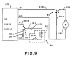
- the trip control circuitry is conventionally constructed and arranged such that in one mode of operation the switch 86 (Figs. 9, 10 and 11) is operated to electrically connect the switch leads 220 and 220B for energizing the solenoid 88.
- the solenoid 88 is energized through a series connected capacitor 272, from the power supply 270.
- the solenoid 88 is operated for a time period which corresponds, substantially, to the charging time constant of the R-C circuit defined by the capacitor 272 and internal resistance 274 of the solenoid 88.
- the switch 86 is operated to electrically disconnect the switch leads 220 and 220B for maintaining deenergization of the solenoid 88, and to electrically connect the switch leads 220 and 220A for discharging the capacitor 272 through a series connected resistor 276.
- the resistance value of the resistor 276 is preferably chosen to ensure that the capacitor 272 does not discharge sufficiently to permit the next operation of the switch 86 to energize the solenoid 88 before the completion of a single revolution of the drum drive gear 26 or cam 180.
- the time constant of the R-C circuit defined by the capacitor 272 and resistor 276 is chosen to maintain the discharge interval of the capacitor 272 for a predetermined time period, preferably corresponding substantially to the time interval during which the drum drive gear 26 and cam 180 complete rotation thereof through a single revolution. Accordingly, the trip switch 86 is disabled from energizing the solenoid 88 for a predetermined time period after any given energization thereof.
- the resistance value of the resistor 276 is preferably chosen to ensure completion of discharge of the capacitor 272 before the next operation of the switch 86 which follows completion of a single revolution of the drum drive gear 26 or cam 180, to permit commencement of the next revolution thereof substantially immediately after completion of any given single revolution thereof.
- the solenoid circuit is in its at-ready mode of operation upon completion of any given single revolution but not during any given revolution thereof.
- the embodiment shown in Fig. 10 differs from that of Figs. 9 and 11, in that the solenoid 88 is energized from the capacitor 272, which is connected across the solenoid 88 when the switch 88 is operated to electrically connect the switch leads 220 and 220B. Again, the solenoid 88 is operated for a time period which corresponds, substantially, to the charging time constant of the R-C circuit defined by the capacitor 272 and the internal resistance 274 of the solenoid 88.
- the embodiment shown in Fig. 10 also differs from that of Fig.
- the switch 86 in that in its other mode of operation the switch 86 is operated to electrically disconnect the switch leads 220 and 220B and connect the switch lead 220 and 220A for charging the capacitor 272, through a series connected resistor 278, from the power supply 270.
- the charging time constant of the capacitor 272 is determined by the time constant of R-C circuit defined by the capacitor 272 and resistor 278.
- the resistance value of the resistor 278 is preferably chosen to ensure that the capacitor 272 does not charge sufficiently to permit the next operation of the switch 86 to energize solenoid 88 bore the completion of a single revolution of the drum drive gear 26 or cam 180.
- the time constant of the R-C circuit defined by the capacitor 272 and resistor 278 is chosen to maintain the charging interval of the capacitor 272 for a predetermined time period corresponding substantially to the time interval during which the drum drive gear 26 and cam 180 complete rotation through a single revolution.
- the trip switch 86 is disabled from energizing the solenoid 88 for a predetermined time period after any given energization thereof.
- the resistance value of the resistor 278 is preferably chosen to ensure completion of charging of the capacitor 272 before the next operation of the switch 86 after the completion of a single revolution of the drum drive gear 26 or cam 180, to permit commencement of the next revolution thereof substantially immediately after completion of any given revolution thereof.
- the solenoid circuit is in its at-ready mode of operation upon completion of any given single revolution thereof but not during any given revolution thereof.
- control circuit 94 includes suitable motor control circuitry for interconnecting the motor switch 90, d.c. motor 240 and power supply 270 for energization and deenergization of the d.c. motor 240 in response to operation of the switch 90.
- the motor control circuitry is conventionally constructed and arranged such that in one mode of operation the switch 90 (Figs. 9 and 11) is operated to electrically disconnect the leads 236 and 236A, for opening a shunt circuit across the d.c. motor 240, and to electrically connect the switch leads 236 and 236B, for energizing the d.c. motor 240 from the power supply 270.
- the switch 90 operated to electrically disconnect the switch leads 236 and 236B, for deenergizing the d.c. motor 240, and to electrically connect the switch leads 236 and 236A, for closing the shunt circuit across the d.c. motor 240 for dynamically braking the d.c. motor 240.
- the shunt circuit is a simple short circuit
- the shunt circuit includes a capacitor 280 and a diode connected in parallel with one another across the motor 240.
- the switch leads 236 and 236B are disconnected for disconnecting the motor 240 from the supply 270, and the switch leads 236 and 236A connected for connecting the shunt circuit 280, 282, across the motor 240.
- the cathode of the diode 282, the side of the capacitor 280 connected thereto and the negative terminal of the motor 240 are connected directly to the ground of the power supply 270.
- the anode of the diode 282, positive terminal of the motor 240 and other side of the capacitor 280 are also electrically connected to the ground of the power supply 270 via the series connected resistor 284, capacitor 272 and solenoid 88.
- the trip switch 86 When the trip switch 86 is operated to connect the switch leads 220 and 220B for energizing the solenoid 88 via the capacitor 272, the side of the capacitor 280 connected to the anode of the diode 282 is connected via the switch 86 to the negative voltage source of the power supply 270, for appropriately charging the capacitor 280 to subsequently discharge through the motor 240 for dynamically braking the motor 240. Thereafter, when the motor switch 90 is operated to disconnect the switch leads 236 and 236A and connect the switch leads 236 and 236B, the motor 240 is energized and the capacitor 280 remains charged.
- the capacitor 280 discharges through the motor 240 causing current to flow in the motor 240 in the appropriate direction that is, opposite to that of the motor operating current, for dynamically braking the motor 240.
- the resistance value of the resistor 284 is selected to ensure that the capacitor 280 is discharged sufficiently rapidly to avoid causing the motor 240 to rotate in the wrong direction.
- the drive system 70 Prior in time to operation of the mailing machine 10 (Fig. 1), the drive system 70 (Fig. 2) is in its normal or at-ready mode of operation, as shown in Figs. 2, 3, 5, 5A and 5B.
- the trip lever 54 As thus shown, the trip lever 54 (Fig. 2) is held, by means of the spring 214, in engagement with trip switch 86, which acts as a travel limiting stop.
- the trip lever shoulder 212 holds the switch 86 in its operating mode wherein the leads 220 and 220A are electrically connected for maintaining the trip solenoid 88 deenergized.
- the spring 124 is connected for urging the control member 100 out of its home position, the control member 100 is held in its home position by the latching member 154, against rotation by the spring 124, since the latching member's latching surface 166 is held in engagement with the control member's latching surface 112 by the spring 124.
- the control member's cam surface 116 is located out of engagement with the cam 180.
- the actuating member 130 (Fig. 5 and 5A) is urged into locking relationship with the rotary cam 180, by the spring 122.
- the actuating member's lever arm 40 is held in engagement with the control member's latching surface 114 by the spring 122.
- the actuating member's lever arm 40 positions the shutter bar key portion 24 (Fig. 1) in the drum drive gear slot 30, thereby locking the drum drive gear 30 and thus the drum 24 against rotation, positions the lever arm's key leg 134 (Figs. 5 and 5A) in the rotary cam's slot 190, thereby locking the cam 180 against rotation, positions the lever arm's stop surface 142 out of contact with the housing stop 143 and positions the motor switch actuating shoulder 144 out of engagement with the motor switch 90.
- the actuating member 130 is thus held, the actuating member's cam surface 140 is located out of engagement with the cam 180. Since the latching member 154 (Fig. 3) holds the control member 100 in place against rotation by the spring 124 (Figs.
- the control member 100 cannot pivot the actuating member's lever arm 40.
- the catching member 154 indirectly prevents actuation of the motor switch 90, holds the shutter bar lever arm's key portion 24 (Fig. 1) in the drum drive gear slot 30 and holds the lever arm's key leg 134 (Figs. 5 and 5B) in the cam slot 90, whereby the drum 24 (Fig. 1) and cam 180 (Figs. 5 and 5B) are locked in their respective home positions.
- the motor switch 90 (Fig. 2) is maintained in its mode of operation wherein the leads 236 and 236B (Fig. 9) are disconnected for preventing the d.c.
- the latching member 150 rotates about the shaft 152, the latching member's latching surface 166 arcuately moves out of engagement with the control member's latching surface 112 (Fig. 6), thereby releasing the control member 100 and permitting rotation thereof by the spring 124.
- the free end of the flexure limiting leg 158 bridges the slot 162 for engaging leg 156, to limit the flexure of the leaf spring leg 156.
- the control member 100 pivots the actuating member's lever arm 40 away from the cam 180, thereby moving the shutter bar key portion 34 (Fig.
- the capacitance value of the capacitor 272 (Figs. 9, 10 and 11) is conventionally selected to ensure that the switch 90 is actuated before the solenoid 88 is deenergized.
- the capacitor 272 becomes sufficiently charged (Figs.9 and 11) or discharged (Fig. 10), as the case may be, to cause the solenoid 88 to be deenergized after the switch 90 is actuated, although the switch leads 220 and 220B may be maintained electrically connected by the trip lever shoulder 212 (Fig. 2).
- the latching member 150 (Fig. 3) is rotated about the pivot shaft 152 by the leaf spring leg 156, thereby causing the latching member's cam follower surface 164 (Fig.
- switch leads 236 and 236A are electrically disconnected for removing the shunt circuit from across the d.c. motor 240, followed by the switch leads 236 and 236B being electrically connected for energizing the d.c. motor 240 from the power supply 270.
- the peripheral velocity of the ejection roller 62 is greater than that of the impression roller 60, as a result of which the ejection roller 62 tends to pull respective sheets 20 which are fed thereto from beneath drum 24 while the drum 24 and impression roller 60 are still rotating in engagement with the sheets 20.
- the ejection roller shaft 63 continues rotation and stores energy in the coil spring 62B as the ejection roller rim 62A slips relative to the shaft 63, until the drum 24 is no longer in engagement with the sheet 20.
- the coil spring 62B releases the energy stored therein by driving the ejection roller rim 62A for feeding the sheet from the machine 10.
- the ejection roller 62 feeds the sheet 20 out of engagement with the trip lever 54.
- the trip lever 54 is rotated about the pivot shaft 202 (Fig.2) by the spring 214, causing the trip lever's shoulder 212 to operate the trip switch 86 for disconnecting the switch leads 220 and 220B and connecting the switch leads 220 and 220A for returning the trip switch 86 to its at-ready mode of operation.
- the trip switch 86 (Fig.2) is returned to its at-ready mode of operation, as hereinbefore discussed, the trip switch 86 is disabled from energizing the solenoid 88 for a predetermined time period after any given energization thereof.
- the time period preferably corresponds substantially to the time interval during which the cam 180 or drum drive gear 26 complete rotation thereof through a single revolution. Accordingly, if a next sheet 20 were fed to the machine 10 after return of the trip switch 86 to its at-ready mode of operation, but before completion of a single revolution of the cam 180 or drum drive gear 26, movement of the trip lever 40 by the sheet 20, sufficiently to operate the switch 86, would not result in energization of the solenoid 88.
- the solenoid circuit is constructed and arranged to prevent the drive mechanism 72 from being double tripped during any given single cycle of operation thereof, thereby ensuring single revolution operation of the drive mechanism 72 and preventing sheets 20 from being jammed between the drum 24 (Fig. 1) and impression roller 60, and ejection roller 62 and idler roller 66.
- the actuating member's cam follower surface 140 When the actuating member 130 is thus held by the control member 100, the actuating member's cam follower surface 140 is located in a plane which is slightly spaced apart from, and which extends substantially parallel to, the rotary cam's camming surface 188 (Fig. 6). Thus the cam follower surface 140 is not initially disposed in engagement with the cam surface 188, due to the spring 124 holding the actuating member's lever arm 40 against the stop 143. Moreover, when the cam 180 commences rotation, the control member's cam follower surface 116 is located out of engagement with the cam's peripherally-extending cam surface 184.
- the rotating cam 180 continues to maintain the shutter bar's key portion 34 (Fig. 1) out of the drum drive gear slot 30, and continues to maintain the actuating member's key leg 134 (Figs. 8A and 8B) out of cam slot 190, until the cam 180 rotates still further and disengages the cam follower surface 140.
- the spring 122 rotates the actuating member 130 (Figs. 5, 5A and 5B) into engagement with the latched control member 100, thereby urging the shutter bar's key portion 24 (Fig. 1) into the drum drive gear slot 30 to prevent further rotation of the drum drive gear 26 and thus the drum 24, moving the actuating member's key leg 134 (Figs.
- the switch leads 236 and 236B are electrically disconnected for deenergizing the d.c. motor 240, followed by the switch leads 236 and 236A being electrically connected to close the shunt circuit across the d.c. motor 240 for dynamically braking the d.c. motor 240.
- the d.c. motor 240 is both deenergized and dynamically braked as the shutter bar key portion 24 (Fig. 1) enters the drum drive gear slot 30 and the actuating member's key leg 134 (Figs.
Landscapes
- Physics & Mathematics (AREA)
- General Physics & Mathematics (AREA)
- Devices For Checking Fares Or Tickets At Control Points (AREA)
- Mechanisms For Operating Contacts (AREA)
Description
- The present invention relates to a machine (e.g. a mailing machine) with a control circuit for disabling a trip switch (e.g. so as to prevent a premature second activation of a printing drum of the mailing machine).
- As shown in U.S. Patent No. 2,934,009, issued April 26, 1962, Bach, et al. and assigned to the assignee of the present invention, there is described a mailing machine which includes a postage meter and a base on which the postage meter is removably mounted. The postage meter includes a rotary printing drum and a drive gear therefor which are mounted on a common shaft and normally located in a home position. The base includes a drive mechanism having an output gear which is disposed in meshing engagement with the drum drive gear when the postage meter is mounted on the base. The drive mechanism includes a single revolution clutch, having a helical spring, for rotating the drum from the home position and into engagement with a letter fed to the drum. Each revolution of the clutch, and thus of the drum, is initiated by a letter engaging a trip lever to release the helical spring. In the course of each drum revolution, the drum prints a postage value on the letter while feeding the same downstream beneath the drum as the drum returns to its home position. Thus the drive mechanism intermittently operates the rotary printing drum.
- Although the single revolution clutch structure has served as the workhorse of the mailing machine industry for many years, it has long been recognized that it is a complex mechanism which is relatively expensive to construct and maintain, tends to be unreliable in high volume applications, and is noisy and thus irritating to customers.
- US-A-4,763,575 discloses a mailing machine having the features recited in the preamble of
claim 1 of the present specification. - According to the invention there is provided a machine comprising driving means, means for feeding a sheet through and from the machine, means for sensing a sheet, and circuit means for controlling the driving means, the circuit means including a trip switch actuatable in response to the sensing means sensing a sheet fed to the machine; characterized in that: the machine further comprises a rotary timing cam, and an actuating member movable into and out of locking engagement with the cam; the circuit means includes a source of supply of d.c. power; the driving means is arranged to be responsive to actuation of the trip switch to cause the actuating member to move out of locking engagement with the cam and then to cause the cam to rotate; and the circuit means includes means for disabling the trip switch for a predetermined time period after the driving means commences rotating the cam.
- The invention will be better understood from the following illustrative description given with reference to the drawings, wherein like reference numerals designate like or corresponding parts throughout the several views:
- FIG. 1 is a partially phantom, perspective, view of a prior art mailing machine, including a postage meter removably mounted on a base, also showing apparatus according to an example of the invention for mounting and driving the impression roller and ejection roller;
- FIG. 2 is a partially schematic, perspective, view of a drive system according to an example of the invention, including the drive mechanism and control system therefor, and relevant apparatus functionally associated therewith;
- FIG. 3 is a partially schematic, top, view of the control system of Fig. 2, showing the latching member thereof and its functional interfacing relationship with the remainder of the drive mechanism;
- FIG. 4 is a plan view of the actuating member of the drive mechanism of Fig. 2, showing the relevant functional portions of the actuating member, including the lever arm portion thereof;
- FIG. 5 is a plan view of drive mechanism of Fig. 2 shown in its normal or at-ready mode of operation;
- FIG. 5A is a side view of the rotary cam of the drive mechanism of Fig. 5;
- FIG. 5B is a partial top view of the drive mechanism of fig. 5;
- FIG. 6 is a plan view, similar to Fig. 5, showing the drive mechanism when the latching member thereof has been moved to its unlatching position to release the control member for carrying the actuating member out of locking relationship with the cam and causing the actuating member to actuate the motor switch;
- FIG. 6A is a side view of the rotary cam of the drive mechanism of Fig. 6;
- FIG. 6B is a partial top view of the drive mechanism of Fig. 6;
- FIG. 7 is a plan view, similar to Fig. 6, showing the drive mechanism when the control member thereof has been partially pivoted by the rotary cam to permit the latching member to return to its latching position;
- FIG. 7A is a side view of the rotary cam of the drive mechanism of Fig. 7;
- FIG. 7B is a partial top view of the drive mechanism of Fig. 7;
- FIG. 8 is a plan view, similar to Fig. 7, showing the drive mechanism when the control member has been fully pivoted by the rotary cam, released thereby and re-latched by the latching member;
- FIG. 8A is a side view of the rotary cam of the drive mechanism of Fig. 8;
- FIG. 8B is a partial top view of the drive mechanism of Fig. 8;
- FIG. 9 is a schematic view of the control circuit of Fig. 2 showing the components thereof when the drive mechanism is in its normal or at-ready mode of operation as shown in Fig. 5, 5A and 5B;
- FIG. 10 is a schematic view, similar to Fig. 9, of another embodiment of the solenoid operating circuitry of Fig. 9; and
- FIG. 11 is a schematic view, similar to Fig. 9, of another embodiment of Fig. 9.
- As shown in FIG. 1, apparatus in which the invention may be incorporated includes a
mailing machine 10 which includes abase 12, having ahousing 14, and apostage meter 16 which is removably mounted on thebase 12. When mounted on thebase 12, thepostage meter 16 forms therewith a slot 15 through whichsheets 20, including mailpieces such as letters, envelopes, cards or other sheet-like materials, may be fed in a downstream path oftravel 22. - The postage meter 16 (Fig. 1) includes rotary printing structure including a
postage printing drum 24 and adrive gear 26 therefor. Thedrum 24 anddrive gear 26 are spaced apart from one another and mounted on a commondrum drive shaft 28. Thedrum 24 is conventionally constructed and arranged for feeding therespective sheets 20 in the path oftravel 22, which extends beneath thedrum 24, and for printing postage data, registration data or other selected indicia on the upwardly disposed surface of eachsheet 20. Thedrum drive gear 26 has akey slot 30 formed therein, which is located vertically beneath thedrum drive shaft 28 when thepostage meter drum 24 anddrive gear 26 are located in their respective home positions. Thepostage meter 16 additionally includes ashutter bar 32, having an elongate key portion 34 which is transversely dimensioned to fit into the drive gear'skey slot 30. Theshutter bar 32 is conventionally reciprocably mounted within themeter 16 for movement toward and away from thedrum drive gear 26, to permit moving the shutter bar's key portion 34 into and out of thekey slot 30, under the control of themailing machines base 10, when thedrum drive gear 26 is located in its home position. To that end, theshutter bar 32 has achannel 36 formed thereinto, from its lower surface 38, and, the mailing machine'sbase 12 includes amovable lever arm 40, having an arcuately-shapedupper end 42, which extends upwardly through anaperture 44 formed in thehousing 14. When themeter 14 is mounted on thebase 10, the lever arm'supper end 42 fits into thechannel 36 in bearing engagement with theshutter bar 32 for reciprocally moving thebar 32, to and between one position, wherein shutter bar's key portion 34 is located in the drum drive gear'skey slot 30, for preventing rotation of thedrum drive gear 26, and another position wherein the key portion 34 is located out of thekey slot 30, for permitting rotation of thedrum drive gear 26. And, for driving thedrum gear 26, thebase 12 includes a drivesystem output gear 46 which extends upwardly through anotherhousing aperture 48 and into meshing engagement with thedrum gear 26. - The base 12 (Fig. 1) additionally includes sheet aligning structure including a
registration fence 50 against which anedge 52 of a givensheet 20 may be urged when fed to themailing machine 10. Further, thebase 12 includes drive system trip structure forsensing sheets 20 fed to themachine 10, including atrip lever 54 which extends upwardly through anotherhousing aperture 58 and into the path oftravel 22 of eachsheet 20 fed to themailing machine 10. Moreover, thebase 12 includes a conventionalinput feed roller 60, known in the art as an impression roller. Theimpression roller 60 is suitably secured to or integrally formed with a driven shaft 61. And the shaft 61 is resiliently connected to thehousing 14, as hereinafter set forth in greater detail, for causing theroller 60 to extend upwardly through thehousing aperture 58 and into the path oftravel 22 for urging eachsheet 20 into printing engagement with thedrum 24 and cooperating therewith for feeding thesheets 20 through themachine 10. - For feeding sheets 20 (Fig. 1) from the
mailing machine 10, thebase 12 includes a conventionaloutput feed roller 62, known in the art as an ejection roller. Theroller 62 includes a cylindrically-shaped rim 62A and a coil spring 62B connecting the rim 62A to a hubbed, drivenshaft 63. Thus the rim 62A is driven by theshaft 63 via the coil spring 62B. And theshaft 63 is rotatably connected to thehousing 14, as hereinafter set forth in greater detail, for causing theroller 62 to extend upwardly through afurther housing aperture 64 and into the path oftravel 22. Moreover, thepostage meter 16 includes asuitable idler roller 66 which is conventionally yieldably mounted, to accommodate mixed thickness batches ofsheets 20, with its axis disposed parallel with the axis of theejection roller 62, when themeter 16 is mounted on thebase 14. As thus mounted, theidler roller 66 extends downwardly into the path oftravel 22. Preferably, theidler roller 66 is also conventionally movably mounted for adjusting vertical spacing thereof from theejection roller 62, to accommodate feeding a given batch of relativelythick sheets 20, such as a batch of envelopes which are each stuffed with a letter and inserts. Thus, the rollers, 62 and 66, are constructed and arranged to accommodatefeeding sheets 20 of mixed thickness therebetween and in the path oftravel 22 from themachine 10. - According to a preferred embodiment of the invention, the base 12 (Fig. 1), and thus the
mailing machine 10, includes an elongateimpression roller carriage 67 which includes a pair of parallel-spacedside walls 67A, one of which is shown, and a lower wall 67B which extends between and is suitably secured to or integrally formed with theside walls 67A. Thecarriage 67 generally horizontally extends from theejection roller shaft 63, and beneath and in supporting relationship with the impression roller shaft 61. More particularly, one end of each of thecarriage side walls 67A is preferably pivotably attached to thehousing 14 so as to define parallel-spaced arcuately-shaped bearing surfaces 67C within which theejection roller shaft 63 is rotatably mounted. Moreover, theside walls 67A are conventionally constructed and arranged for rotatably supporting the opposed ends of the impression roller shaft 61. And, the carriage 67B lower wall is preferably connected to thehousing 14 by means of a dependingspring 68. Further, thebase 12 includes a drivengear 61A which is suitably fixedly connected to or integrally formed with the impression roller shaft 61. Thus, the impression roller shaft 61 and drivegear 61A are both conventionally rotatably connected to thecarriage 67. In addition, thebase 12 includes a drivengear 63A which is suitably fixedly connected to or integrally formed with theejection roller shaft 63. And, thebase 12 includes anendless gear belt 69 which is looped about thegears gear 61A to thegear 63A, whereby theejection roller shaft 63 and theimpression roller 60 are driven in timed relationship with one another. Moreover, thegears impression roller 60 andejection roller 62, are relatively dimensioned for ensuring that the peripheral velocity of theejection roller 62 is greater than the peripheral velocity of theimpression roller 60, when neither of therespective rollers sheet 20 fed thereto. As thus constructed and arranged, when theimpression roller 60 is urged downwardly, the impression roller drive shaft 61 and drivegear 61A therefor are urged downwardly as the supportingcarriage 67 pivots downwardly about theejection roller shaft 63, against the force exerted on thecarriage 67 by thespring 68, to provide a variable gap between thedrum 24 andimpression roller 60, to accommodatemixed thickness sheets 20. And thespring 68 resiliently urges thecarriage 70, and thus theimpression roller 60, upwardly against any downwardly directed force exerted on theimpression roller 60, by a givensheet 20 fed beneath thepostage meter drum 24, for urgingmixed thickness sheets 20 into printing engagement with thedrum 24. - In addition, the base 12 (Fig. 1), and thus the
mailing machine 10, includes an intermittently operable, electromechanical, drive system 70 (Fig. 2) for driving the shutter bar lever arm 40 (Fig. 1),output gear 26 and thus thepostage meter drum 24, and theroller shaft 63 and thus theroller 60, preferably in timed relationship with one another, in response to movement of thetrip lever 54 by asheet 20 fed to themachine 10. - The drive system 70 (Fig. 2) is conventionally supported by the
housing 14 and generally includes adrive mechanism 72 and drivesystem operating apparatus 74. More particularly, the drive mechanism 72 (Fig. 2) comprises a plurality of interactive structures includingcontrol structure 76, actuatingstructure 78, drivemechanism latching structure 80 and rotarytiming cam structure 82. And, the operatingapparatus 74 includestrip lever structure 84, and, in addition, comprises a plurality of components, including atrip switch 86,trip solenoid 88,motor switch 90 and d.c.motor drive system 92, and acontrol circuit 94 to which thecomponents - The control structure 76 (Fig. 2) includes a
control member 100 which is conventionally pivotably mounted for rotation, in a generally vertically-extending plane, on apivot shaft 102 which is secured to or integrally formed with thehousing 14. As viewed in its home position (Fig. 5), thecontrol member 100 includes a vertically oriented, upwardly-extending,leg 104, a laterally-extendingleg 106 and a depending leg 105. The upwardly-extendingleg 104 acts as a cam, latch and stop, and includes acam surface 110, latchingsurface 112 and astop surface 114. The laterally-extendingleg 106 acts as a cam follower and includes acam follower surface 116. And, the dependingleg 108 acts as a lever arm and includes upper andlower slots control structure 76 also includes upper and lower springs, 122 and 124. Theupper spring 122 has one end located in theupper slot 118 for attachment thereof to the dependingleg 108 and has the other end attached to theactuating structure 78. And, thelower spring 124 has one end located in thelower slot 120 for attachment thereof to the dependingleg 108 and has the other end indirectly attached to thehousing 14. - The actuating structure 78 (Fig. 2) includes an actuating
member 130 which is also conventionally pivotably mounted for rotation, in a generally vertically-extending plane, on thepivot shaft 102. The actuating member 130 (Fig. 4) includes an upwardly-extending leg which acts as a lever arm and, in particular, is the shutter baractuating lever arm 40. In addition, the actuatingmember 130 includes opposed legs, 134 and 136, which laterally extend from the actuatinglever arm 40, and a dependingleg 138. One of the laterally-extendinglegs 134 acts as a cam key and cam follower and is thus transversely dimensioned to act as a key and includes acam follower surface 140. The other laterally-extendingleg 136 acts as a pivot limiter and motor switch actuator, and includes atravel limiting surface 142, which is conventionally formed for contacting ahousing stop 143, and a motorswitch actuating shoulder 144. And, the dependingleg 138 acts as a lever arm and includes a lower slot 146 in which the aforesaid other end of the control structure's upper spring 122 (Fig. 2) is located for attachment thereof to the dependingleg 138. - The drive mechanism latching structure 80 (Fig. 2) includes an latching
member 150 which is conventionally pivotably mounted for rotation, in a generally horizontally-extending plane, on anotherpivot shaft 152 which is secured to or integrally formed with thehousing 14. The latching member 150 (Fig. 3) has a plurality of laterally-extending legs including one laterally-extendingleg 154 which acts as a lever arm and includes a trip solenoidshaft striking surface 155. Another of the laterally-extendinglegs 156 acts as a leaf spring, and yet another of the laterally-extendinglegs 158 acts as a leaf spring flexure limiter. Theleaf spring leg 156 andflexure limiting leg 158 extend substantially parallel to each other and define a longitudinally-extending slot 162 therebetween. And, still another of the laterally-extendinglegs 160 acts as a cam follower and latch, and includes acam follower surface 164 and latchingsurface 166. - The rotary timing cam structure 82 (Fig. 2) includes a generally annularly-shaped
rotary cam 180, which is suitably secured to or integrally formed with adrive shaft 182. The drive shaft 182 (Fig. 5) is conventionally connected to thehousing 14, as by means of a supportingframe 183 which is conventionally removably connected to thehousing 14, to permit rotation of thecam 180 in a generally vertically-extending plane. As viewed from the end of theshaft 182 which extends inwardly of thehousing 14, thecam 180 has an outer, peripherally-extendingcam surface 184, which tapers inwardly toward the viewing end of thedrive shaft 182 to accommodate camming engagement with the control member'scam follower surface 116. Thecam surface 184, when thus viewed and also when viewed as extending counter-clockwise from a line "1" (Fig. 5A) passing through the average radius of thecam surface 184, commences at a radial distance "r₁" from the axis of theshaft 182, spirals outwardly, and ends at a radial distance "r₂" from the axis of theshaft 182. As thus constructed and arranged, thecam 180 also includes a radially-extendingsurface 186 having an average radial width of the sum of r₂ - r₁. Further, as thus viewed, thecam 180 has a generally annularly-shaped inwardly-facingcam surface 188, surrounding thedrive shaft 182, and includes aslot 190 formed thereinto from thesurface 188. Theslot 190 is located vertically above thedrive shaft 182, when thecam 180 is disposed in its home position, and is suitably dimensioned for receiving thereinto the actuating member's key-shaped, laterally-extending,leg 134. - The trip lever structure 84 (Fig. 2) includes a
trip member 200 which is conventionally pivotably mounted for rotation, in a generally vertically-extending plane, on apivot shaft 202 which is secured to or integrally formed with thehousing 14. Thetrip member 200 includes an upwardly extending leg, known in the art as thetrip lever 54, and a dependingleg 204, which acts as a lever arm and includes aslot 206 formed therein. Thetrip lever 54 preferably includes an upper, laterally-extending,shoulder 208, having an arcuately-extendingupper edge 210 which extends towardsrespective sheets 20 fed thereto for supporting and guidingsuch sheets 20 into the path oftravel 22 when thetrip lever 54 is engaged and moved bysuch sheets 20. In addition, thetrip lever 54 includes a lower, laterally-extending tripswitch actuating shoulder 212. Thetrip lever structure 84 further includes aspring 214, having one end located in the depending leg'sslot 206 and the other end conventionally connected to thehousing 14. - The trip switch 86 (Fig. 2) is preferably a single pole double throw switch having two modes of operation. The
switch 86 is conventionally physically connected to thehousing 14 for suitable location of theswitch 86 relative to the trip lever'sswitch actuating shoulder 212, to allow theshoulder 212 to operate theswitch 86 in response to movement of thetrip lever 54. Theswitch 86 includes anoperating lead 220 and two switch position, leads, 220A and 220B. When theswitch 86 is in one of its modes of operation, theleads switch 86 is in its other mode of operation, theleads - The trip solenoid 88 (Fig. 2) is preferably a conventional D.C. solenoid which includes a core or
shaft 230. Thesolenoid 88 is conventionally physically connected to thehousing 14 for suitably locating theshaft 230 relative to the latchingmember 150 to allow theshaft 230 to strike thesurface 155 of the latchingmember 150 and pivot the latchingmember 150 against the force exerted thereon by theleaf spring 156, when thesolenoid 88 is energized from thecontrol circuit 94. - The motor switch 90 (Fig. 2) is preferably a single pole double throw switch having two modes of operation. The
switch 90 is conventionally physically connected to thehousing 14 for suitable location of theswitch 90 relative to the actuating member lever arm'sswitch actuating shoulder 144, to allow theshoulder 144 to operate theswitch 90 in response to movement of the actuating member'slever arm 40. Theswitch 90 includes anoperating lead 236 and two switch position leads 236A and 236B. When theswitch 90 is in one of its modes of operation, theleads switch 90 in its other mode of operation, theleads - The d.c. motor drive system 92 (Fig. 2) preferably includes a conventional d.c. motor, 240 having an
output shaft 242. Themotor 24 is conventionally physically connected to thehousing 14 via agear box 244. Themotor output shaft 242 is preferably connected, via areduction gear train 246 within thegear box 244, to anoutput drive gear 248, which is suitably journalled to thegear box 244 for rotation. Thedrive system 92 additionally includes a timingcam drive gear 250 andgear belt 252. Thecam drive gear 250 is suitably fixedly connected to or integrally formed with thecam drive shaft 182. Thus, thecam 180 is mounted for rotation with thedrive gear 250. And, thegear belt 252 is endlessly looped about and disposed in meshing engagement with thedrive gear 248 andcam drive gear 250. Thedrive system 92 further includes an ejectionroller drive gear 254 and adrive shaft 256 on which thegear 254 is conventionally fixedly mounted. Thedrive shaft 256 is suitably rotatably connected to thehousing 14 for conventionally connecting one end thereof to theejection roller shaft 63A (Fig. 1) and disposing the ejection roller drive gear 254 (Fig. 2) in meshing engagement with thegear belt 252, between the motoroutput drive gear 248 and timingcam drive gear 250. Moreover, thedrive system 92 additionally includes the drivesystem output gear 46, (Fig. 2), which is suitably fixedly connected to or integrally formed with thecam drive shaft 182 for rotation therewith and extends upwardly through thehousing 14 for engagement with the drum drive gear 26 (Fig. 1). Thus, thecam 180 is mounted for rotation with the output gear 46 (Fig. 1) and drivegear 26. - The control circuit 94 (Fig. 2) preferably includes a conventional d.c.
power supply 270. In addition, thecontrol circuit 94 includes suitable trip control circuitry for interconnecting thetrip switch 86,trip solenoid 88 andpower supply 270 for energization of thesolenoid 88 in response to operation of theswitch 86. Preferably, the trip control circuitry is conventionally constructed and arranged such that in one mode of operation the switch 86 (Figs. 9, 10 and 11) is operated to electrically connect the switch leads 220 and 220B for energizing thesolenoid 88. - In the embodiments shown in Fig. 9 and 11, the
solenoid 88 is energized through a series connectedcapacitor 272, from thepower supply 270. Thus thesolenoid 88 is operated for a time period which corresponds, substantially, to the charging time constant of the R-C circuit defined by thecapacitor 272 andinternal resistance 274 of thesolenoid 88. In the other mode of operation theswitch 86 is operated to electrically disconnect the switch leads 220 and 220B for maintaining deenergization of thesolenoid 88, and to electrically connect the switch leads 220 and 220A for discharging thecapacitor 272 through a series connectedresistor 276. In either of the embodiments (Fig.9 or 11), the resistance value of theresistor 276 is preferably chosen to ensure that thecapacitor 272 does not discharge sufficiently to permit the next operation of theswitch 86 to energize thesolenoid 88 before the completion of a single revolution of thedrum drive gear 26 orcam 180. Thus the time constant of the R-C circuit defined by thecapacitor 272 andresistor 276 is chosen to maintain the discharge interval of thecapacitor 272 for a predetermined time period, preferably corresponding substantially to the time interval during which thedrum drive gear 26 andcam 180 complete rotation thereof through a single revolution. Accordingly, thetrip switch 86 is disabled from energizing thesolenoid 88 for a predetermined time period after any given energization thereof. Moreover, the resistance value of theresistor 276 is preferably chosen to ensure completion of discharge of thecapacitor 272 before the next operation of theswitch 86 which follows completion of a single revolution of thedrum drive gear 26 orcam 180, to permit commencement of the next revolution thereof substantially immediately after completion of any given single revolution thereof. Thus the solenoid circuit is in its at-ready mode of operation upon completion of any given single revolution but not during any given revolution thereof. - The embodiment shown in Fig. 10 differs from that of Figs. 9 and 11, in that the
solenoid 88 is energized from thecapacitor 272, which is connected across thesolenoid 88 when theswitch 88 is operated to electrically connect the switch leads 220 and 220B. Again, thesolenoid 88 is operated for a time period which corresponds, substantially, to the charging time constant of the R-C circuit defined by thecapacitor 272 and theinternal resistance 274 of thesolenoid 88. The embodiment shown in Fig. 10 also differs from that of Fig. 9 and 10 in that in its other mode of operation theswitch 86 is operated to electrically disconnect the switch leads 220 and 220B and connect theswitch lead capacitor 272, through a series connectedresistor 278, from thepower supply 270. Thus, the charging time constant of thecapacitor 272 is determined by the time constant of R-C circuit defined by thecapacitor 272 andresistor 278. In this embodiment (Fig.10) the resistance value of theresistor 278 is preferably chosen to ensure that thecapacitor 272 does not charge sufficiently to permit the next operation of theswitch 86 to energizesolenoid 88 bore the completion of a single revolution of thedrum drive gear 26 orcam 180. Thus the time constant of the R-C circuit defined by thecapacitor 272 andresistor 278 is chosen to maintain the charging interval of thecapacitor 272 for a predetermined time period corresponding substantially to the time interval during which thedrum drive gear 26 andcam 180 complete rotation through a single revolution. Again, thetrip switch 86 is disabled from energizing thesolenoid 88 for a predetermined time period after any given energization thereof. Moreover, the resistance value of theresistor 278 is preferably chosen to ensure completion of charging of thecapacitor 272 before the next operation of theswitch 86 after the completion of a single revolution of thedrum drive gear 26 orcam 180, to permit commencement of the next revolution thereof substantially immediately after completion of any given revolution thereof. The solenoid circuit is in its at-ready mode of operation upon completion of any given single revolution thereof but not during any given revolution thereof. - Further, the control circuit 94 (Fig. 2) includes suitable motor control circuitry for interconnecting the
motor switch 90, d.c.motor 240 andpower supply 270 for energization and deenergization of the d.c.motor 240 in response to operation of theswitch 90. Preferably, the motor control circuitry is conventionally constructed and arranged such that in one mode of operation the switch 90 (Figs. 9 and 11) is operated to electrically disconnect theleads motor 240, and to electrically connect the switch leads 236 and 236B, for energizing the d.c. motor 240 from thepower supply 270. And, in the other mode of operation theswitch 90 operated to electrically disconnect the switch leads 236 and 236B, for deenergizing the d.c.motor 240, and to electrically connect the switch leads 236 and 236A, for closing the shunt circuit across the d.c.motor 240 for dynamically braking the d.c.motor 240. In the embodiment shown in Fig. 9, the shunt circuit is a simple short circuit,whereas in the embodiment shown in Fig. 11, the shunt circuit includes acapacitor 280 and a diode connected in parallel with one another across themotor 240. When theswitch 90 is in its at-ready mode of operation as shown in Fig. 11, the switch leads 236 and 236B are disconnected for disconnecting themotor 240 from thesupply 270, and the switch leads 236 and 236A connected for connecting theshunt circuit motor 240. In addition, the cathode of thediode 282, the side of thecapacitor 280 connected thereto and the negative terminal of themotor 240 are connected directly to the ground of thepower supply 270. And, the anode of thediode 282, positive terminal of themotor 240 and other side of thecapacitor 280 are also electrically connected to the ground of thepower supply 270 via the series connectedresistor 284,capacitor 272 andsolenoid 88. When thetrip switch 86 is operated to connect the switch leads 220 and 220B for energizing thesolenoid 88 via thecapacitor 272, the side of thecapacitor 280 connected to the anode of thediode 282 is connected via theswitch 86 to the negative voltage source of thepower supply 270, for appropriately charging thecapacitor 280 to subsequently discharge through themotor 240 for dynamically braking themotor 240. Thereafter, when themotor switch 90 is operated to disconnect the switch leads 236 and 236A and connect the switch leads 236 and 236B, themotor 240 is energized and thecapacitor 280 remains charged. On the other hand, when themotor switch 90 is subsequently operated to disconnect the switch leads 236 and 236B, for deenergizing themotor 270, and to connect the switch leads 236 and 236A, for connecting theshunt circuit motor 240, thecapacitor 280 discharges through themotor 240 causing current to flow in themotor 240 in the appropriate direction that is, opposite to that of the motor operating current, for dynamically braking themotor 240. Preferably, the resistance value of theresistor 284 is selected to ensure that thecapacitor 280 is discharged sufficiently rapidly to avoid causing themotor 240 to rotate in the wrong direction. - Prior in time to operation of the mailing machine 10 (Fig. 1), the drive system 70 (Fig. 2) is in its normal or at-ready mode of operation, as shown in Figs. 2, 3, 5, 5A and 5B. As thus shown, the trip lever 54 (Fig. 2) is held, by means of the
spring 214, in engagement withtrip switch 86, which acts as a travel limiting stop. Moreover, thetrip lever shoulder 212 holds theswitch 86 in its operating mode wherein theleads trip solenoid 88 deenergized. In addition, although thespring 124 is connected for urging thecontrol member 100 out of its home position, thecontrol member 100 is held in its home position by the latchingmember 154, against rotation by thespring 124, since the latching member'slatching surface 166 is held in engagement with the control member'slatching surface 112 by thespring 124. When thecontrol member 100 is thus held, the control member'scam surface 116 is located out of engagement with thecam 180. Further, the actuating member 130 (Fig. 5 and 5A) is urged into locking relationship with therotary cam 180, by thespring 122. And, the actuating member'slever arm 40 is held in engagement with the control member'slatching surface 114 by thespring 122. As thus disposed, the actuating member'slever arm 40 positions the shutter bar key portion 24 (Fig. 1) in the drumdrive gear slot 30, thereby locking thedrum drive gear 30 and thus thedrum 24 against rotation, positions the lever arm's key leg 134 (Figs. 5 and 5A) in the rotary cam'sslot 190, thereby locking thecam 180 against rotation, positions the lever arm'sstop surface 142 out of contact with thehousing stop 143 and positions the motorswitch actuating shoulder 144 out of engagement with themotor switch 90. When the actuatingmember 130 is thus held, the actuating member'scam surface 140 is located out of engagement with thecam 180. Since the latching member 154 (Fig. 3) holds thecontrol member 100 in place against rotation by the spring 124 (Figs. 5 and 5B), thecontrol member 100 cannot pivot the actuating member'slever arm 40. Thus, the catchingmember 154 indirectly prevents actuation of themotor switch 90, holds the shutter bar lever arm's key portion 24 (Fig. 1) in the drumdrive gear slot 30 and holds the lever arm's key leg 134 (Figs. 5 and 5B) in thecam slot 90, whereby the drum 24 (Fig. 1) and cam 180 (Figs. 5 and 5B) are locked in their respective home positions. And, the motor switch 90 (Fig. 2) is maintained in its mode of operation wherein theleads power supply 270, and wherein theleads motor 240, with the result that the d.c.motor 240 is maintained deenergized. - In operation, when a sheet 20 (Fig. 1) is fed to the
base 12, the operator normally urges thesheet edge 52 into engagement with theregistration fence 50 and in the direction of path oftravel 22, whereby thesheet 20 is fed towards and into engagement with thetrip lever 54. The force exerted by the sheet 20 (Fig. 2) against thetrip lever 54 causes thetrip lever 54 to rotate about thepivot shaft 202 against the force exerted by thespring 214. As thetrip lever 54 rotates, the trip lever'sshoulder 212 operates thetrip switch 86, thereby interconnecting the switch leads 220 and 220B for energizing thesolenoid 88 from thepower supply 270. Whereupon the solenoid 88 (Figs. 9, 10 and 11) is maintained energized during the time interval thecapacitor 272 is being charged (Figs. 9 and 11) or discharged (Fig. 10), as the case may be. When thesolenoid 88 is energized, the solenoid's core or shaft 230 (Fig. 2) strikes the latching member'ssurface 155 and exerts sufficient force thereagainst, for a sufficient time period, to cause the latchingmember 150 to rotate about thepivot shaft 152, against the force exerted by the latching member'sleaf spring leg 156, as theleg 156 is flexed against thehousing 14. As the latchingmember 150 rotates about theshaft 152, the latching member'slatching surface 166 arcuately moves out of engagement with the control member's latching surface 112 (Fig. 6), thereby releasing thecontrol member 100 and permitting rotation thereof by thespring 124. Concurrently, the free end of theflexure limiting leg 158 bridges the slot 162 for engagingleg 156, to limit the flexure of theleaf spring leg 156. As thespring 124 rotates thecontrol member 100, thecontrol member 100 pivots the actuating member'slever arm 40 away from thecam 180, thereby moving the shutter bar key portion 34 (Fig. 1) out of the drumdrive gear slot 30 to permit rotation of thedrum drive gear 26, and thus thedrum 24, moving the lever arm's key leg 134 (Figs. 5 and 58) out of thecam slot 190 to permit rotation of thecam 180, moving the lever arm's stop surface 142 (Fig. 2) into contact with thehousing stop 143, and moving the lever arm'sshoulder 144 into engagement with themotor switch 90 to actuate theswitch 90. - Preferably, the capacitance value of the capacitor 272 (Figs. 9, 10 and 11) is conventionally selected to ensure that the
switch 90 is actuated before thesolenoid 88 is deenergized. Thus thecapacitor 272 becomes sufficiently charged (Figs.9 and 11) or discharged (Fig. 10), as the case may be, to cause thesolenoid 88 to be deenergized after theswitch 90 is actuated, although the switch leads 220 and 220B may be maintained electrically connected by the trip lever shoulder 212 (Fig. 2). Upon deenergization of thesolenoid 88 the latching member 150 (Fig. 3) is rotated about thepivot shaft 152 by theleaf spring leg 156, thereby causing the latching member's cam follower surface 164 (Fig. 6B) to be urged into contact with the control member'scam surface 110. And, when theswitch 90 is actuated, the switch leads 236 and 236A are electrically disconnected for removing the shunt circuit from across the d.c.motor 240, followed by the switch leads 236 and 236B being electrically connected for energizing the d.c. motor 240 from thepower supply 270. - When the d.c. motor 240 (Fig. 2) is energized, the
motor output shaft 242 drives thegear train 246 and thus theoutput drip gear 248. And, motor rotation of the drive gear 248 (Fig. 1) is transmitted by thegear belt 252 to thecam drive gear 250,ejection roller drive 254 and drivesystem output gear 46, for rotating, in timed relationship with one another, therotary timing cam 180,ejection roller 62 and thus theimpression roller 60, and thedrum drive gear 26 and thus thepostage meter drum 24. - Accordingly, rotation of the trip lever 54 (Fig. 1) by a
sheet 20 fed thereto eventuates in causing thedrum 24 andimpression roller 60 to commence rotating in timed relationship with one another for feeding thesheet 20 downstream in the path oftravel 22 beneath thedrum 24 and causing theejection roller 62 to commence rotating for feedingsheets 22 engaged thereby from beneath theidler roller 66 and thus from themachine 10. Since the angular velocity of the ejection roller rim 62A is normally greater than the angular velocity of theimpression roller 60, the peripheral velocity of theejection roller 62 is greater than that of theimpression roller 60, as a result of which theejection roller 62 tends to pullrespective sheets 20 which are fed thereto from beneathdrum 24 while thedrum 24 andimpression roller 60 are still rotating in engagement with thesheets 20. When the drag force exerted on the ejection roller rim 62A, by asheet 20 engaged by thedrum 24 andimpression roller 60, exceeds the spring force exerted on the ejection roller rim 62A by the coil spring 62B, theejection roller shaft 63 continues rotation and stores energy in the coil spring 62B as the ejection roller rim 62A slips relative to theshaft 63, until thedrum 24 is no longer in engagement with thesheet 20. Whereupon, the coil spring 62B releases the energy stored therein by driving the ejection roller rim 62A for feeding the sheet from themachine 10. Moreover, theejection roller 62 feeds thesheet 20 out of engagement with thetrip lever 54. Whereupon thetrip lever 54 is rotated about the pivot shaft 202 (Fig.2) by thespring 214, causing the trip lever'sshoulder 212 to operate thetrip switch 86 for disconnecting the switch leads 220 and 220B and connecting the switch leads 220 and 220A for returning thetrip switch 86 to its at-ready mode of operation. - However, although the trip switch 86 (Fig.2) is returned to its at-ready mode of operation, as hereinbefore discussed, the
trip switch 86 is disabled from energizing thesolenoid 88 for a predetermined time period after any given energization thereof. And, the time period preferably corresponds substantially to the time interval during which thecam 180 or drumdrive gear 26 complete rotation thereof through a single revolution. Accordingly, if anext sheet 20 were fed to themachine 10 after return of thetrip switch 86 to its at-ready mode of operation, but before completion of a single revolution of thecam 180 or drumdrive gear 26, movement of thetrip lever 40 by thesheet 20, sufficiently to operate theswitch 86, would not result in energization of thesolenoid 88. Thus the solenoid circuit is constructed and arranged to prevent thedrive mechanism 72 from being double tripped during any given single cycle of operation thereof, thereby ensuring single revolution operation of thedrive mechanism 72 and preventingsheets 20 from being jammed between the drum 24 (Fig. 1) andimpression roller 60, andejection roller 62 andidler roller 66. - As hereinbefore discussed, rotation of the trip lever (Fig. 1) by a
sheet 20 fed thereto which does result in operation of thetrip switch 86 for energizing thesolenoid 88, also eventuates in causing the rotary timing cam 180 (Fig. 2) to commence rotating in timed relationship with the impression roller 60 (Fig. 1),drum 24 andejection roller 66. When the cam 180 (Fig. 6) commences rotation, the actuatingmember 130 is held against thehousing stop 143 due to thespring 124 having rotated thecontrol member 100 when thecontrol member 100 was released by the latchingmember 154. When the actuatingmember 130 is thus held by thecontrol member 100, the actuating member'scam follower surface 140 is located in a plane which is slightly spaced apart from, and which extends substantially parallel to, the rotary cam's camming surface 188 (Fig. 6). Thus thecam follower surface 140 is not initially disposed in engagement with thecam surface 188, due to thespring 124 holding the actuating member'slever arm 40 against thestop 143. Moreover, when thecam 180 commences rotation, the control member'scam follower surface 116 is located out of engagement with the cam's peripherally-extendingcam surface 184. - As the cam (Fig. 7 and 7A) continues rotating, the cam's peripherally-extending
cam surface 184 slidably engages the control member'scam follower surface 116 and, due to thecam surface 184 spiraling outwardly relative to the axis of thecam drive shaft 182, thecontrol member 100 is gradually rotated clockwise about thepivot shaft 102 against the correspondingly gradually increasing force exerted by thespring 124. Since actuating member 130 (Fig. 2) is held against thecontrol member 100 by thespring 122, the actuatingmember 130 rotates in unison with thecontrol member 100 until the actuating member's cam follower surface (Figs. 7 & 7A) contacts the rotatingcam surface 188. Whereupon, further movement of the actuatingmember 130 is stopped, while thecontrol member 100 continues to be rotated by thecam 180. As a result, continued rotation of thecontrol member 100 is accomplished against the gradually increasing forces exerted by both thespring member 130 is held by thecam 180, since the latching member'scam follower surface 164 is disposed in sliding engagement with the control member'scam surface 110, the latchingmember 154 is gradually rotated about the pivot shaft 152 (Fig. 3) against the force exerted by theleaf spring leg 156, until the control member'slatching surface 112 is rotated beyond the latching member'slatching surface 166. Whereupon theleaf spring leg 156 rotates the latching member'slatching surface 166 into facing relationship with the control member'slatching surface 112. - Thereafter, as the cam 180 (Fig. 8) still further continues rotation, the cam's peripherally-extending
cam surface 184 disengages the control member'scam follower surface 116. As a result, the control member'sspring 124 urges the control member'slatching surface 112 into latching engagement with the latching member'slatching surface 166, thereby holding the latching member 154 (Fig. 3) against any further rotation until the solenoid 88 (Fig. 2) is re-energized. When the control member 100 (Figs. 8A and 8B) is thus initially latched in place, thecam 180 has not yet rotated sufficiently to disengage thecam surface 188 from the actuator member'scam follower surface 140. Accordingly, the rotatingcam 180 continues to maintain the shutter bar's key portion 34 (Fig. 1) out of the drumdrive gear slot 30, and continues to maintain the actuating member's key leg 134 (Figs. 8A and 8B) out ofcam slot 190, until thecam 180 rotates still further and disengages thecam follower surface 140. Whereupon, thespring 122 rotates the actuating member 130 (Figs. 5, 5A and 5B) into engagement with the latchedcontrol member 100, thereby urging the shutter bar's key portion 24 (Fig. 1) into the drumdrive gear slot 30 to prevent further rotation of thedrum drive gear 26 and thus thedrum 24, moving the actuating member's key leg 134 (Figs. 5, 5A and 5B) into thecam slot 190 and concurrently urging the actuating member'sshoulder 144 out of engagement with themotor switch 90 for actuating theswitch 90. When theswitch 90 is actuated, the switch leads 236 and 236B are electrically disconnected for deenergizing the d.c.motor 240, followed by the switch leads 236 and 236A being electrically connected to close the shunt circuit across the d.c.motor 240 for dynamically braking the d.c.motor 240. As a result, the d.c.motor 240 is both deenergized and dynamically braked as the shutter bar key portion 24 (Fig. 1) enters the drumdrive gear slot 30 and the actuating member's key leg 134 (Figs. 5, 5A and 5B) enters the cam'sslot 190. And, when thespring 122 has rotated the actuatingmember 130 into engagement with the latchedcontrol member 100, the shutter bar key portion 24 (Fig. 1) locks the drum drive gear and thus thedrum 24 in their respective home positions, and the actuating member's key leg 134 (Figs. 5, 5A and 5B) locks thecam 180 in its home position, thereby returning the drive system 70 (Fig. 2) to its normal or at-ready mode of operation. - There has been described a simplified rotary printing structure drive system, including a control circuit therefor, which ensures single cycle operation thereof. Although the invention disclosed herein has been described with reference to particular embodiments thereof, variations and modifications may be made therein by persons skilled in the art, without departing from the invention as defined in the independent claim and as interpreted in accordance with
EPC Article 69 and its Protocol.
Claims (7)
- A machine comprising driving means (72), means (24, 60, 62, 66) for feeding a sheet (20) through and from the machine, means (84) for sensing a sheet, and circuit means (74) for controlling the driving means (72), the circuit means including a trip switch (86) actuatable in response to the sensing means (84) sensing a sheet fed to the machine;
characterized in that:
the machine further comprises a rotary timing cam (82), and an actuating member (130) movable into and out of locking engagement with the cam;
the circuit means (74) includes a source (270) of supply of d.c. power;
the driving means (72) is arranged to be responsive to actuation of the trip switch (86) to cause the actuating member (130) to move out of locking engagement with the cam (82) and then to cause the cam to rotate; and
the circuit means includes means (272, 276) for disabling the trip switch (86) for a predetermined time period after the driving means (72) commences rotating the cam (82). - The machine according to claim 1, wherein the predetermined time period corresponds to a time interval during which the cam (82) is completing rotation thereof through a single revolution.
- The machine according to claim 1 or 2, wherein the circuit means (74) includes a capacitor (272) and a solenoid (88) energizable from the power supply (270) through the capacitor in response to actuation of the trip switch (86) when a sheet is fed to the machine.
- The machine according to claim 1 or 2, wherein the circuit means (74) includes a capacitor (272) arranged to be charged from the power supply (270) before the trip switch (86) is actuated, and a solenoid (88) energizable from the capacitor in response to actuation of the trip switch when a sheet is fed to the machine.
- The machine according to claim 3, wherein the circuit means (74) includes a resistor (276) arranged to be connected to the capacitor (272) after actuation of the trip switch (86) for delaying discharge of the capacitor for the predetermined time period.
- The machine according to claim 4, wherein the circuit means (74) includes a resistor (278) arranged to be connected to the capacitor (272) after actuation of the trip switch (86) for delaying charging of the capacitor for the predetermined time period.
- The improvement according to claim 1, wherein the predetermined time period ends when the cam (82) has completed a single revolution thereof.
Applications Claiming Priority (2)
| Application Number | Priority Date | Filing Date | Title |
|---|---|---|---|
| US07/307,558 US4936568A (en) | 1989-02-08 | 1989-02-08 | Control circuit for single revolution means |
| US307558 | 1999-05-10 |
Publications (3)
| Publication Number | Publication Date |
|---|---|
| EP0382499A2 EP0382499A2 (en) | 1990-08-16 |
| EP0382499A3 EP0382499A3 (en) | 1991-04-24 |
| EP0382499B1 true EP0382499B1 (en) | 1995-03-01 |
Family
ID=23190274
Family Applications (1)
| Application Number | Title | Priority Date | Filing Date |
|---|---|---|---|
| EP90301281A Expired - Lifetime EP0382499B1 (en) | 1989-02-08 | 1990-02-07 | Machine with control circuit for disabling a trip switch |
Country Status (5)
| Country | Link |
|---|---|
| US (1) | US4936568A (en) |
| EP (1) | EP0382499B1 (en) |
| AU (1) | AU4924590A (en) |
| CA (1) | CA2008966A1 (en) |
| DE (1) | DE69017238T2 (en) |
Families Citing this family (4)
| Publication number | Priority date | Publication date | Assignee | Title |
|---|---|---|---|---|
| US4881461A (en) * | 1989-02-08 | 1989-11-21 | Pitney Bowes Inc. | Mailing machine including improved driving means circuit |
| US4905980A (en) * | 1989-02-08 | 1990-03-06 | Pitney Bowes Inc. | Control circuit for single revolution means |
| GB8929364D0 (en) * | 1989-12-30 | 1990-02-28 | Alcatel Business Systems | Clutch and brake mechanism for franking machine |
| US5495103A (en) * | 1994-03-16 | 1996-02-27 | Ascom Hasler Mailing Systems Ag | Optical mail piece sensor for postage meter |
Family Cites Families (19)
| Publication number | Priority date | Publication date | Assignee | Title |
|---|---|---|---|---|
| GB191204683A (en) * | 1911-04-26 | 1912-07-11 | Soennecken F | Improvements in or relating to Machines for Copying Documents and the like. |
| US1077818A (en) * | 1912-07-05 | 1913-11-04 | Gen Electric | Detector for printing-presses or the like. |
| DE488217C (en) * | 1927-11-13 | 1929-12-21 | Alfons Grutza | Surface carburetor for internal combustion engines |
| GB576267A (en) * | 1943-03-12 | 1946-03-26 | Pitney Bowes Postage Meter Co | Improvements in letter controlled mechanism |
| DE918640C (en) * | 1951-06-10 | 1954-09-30 | Roto Werke A G | Rotary multiplier with motor drive |
| US2766569A (en) * | 1952-10-01 | 1956-10-16 | Pitney Bowes Inc | Mail treating and inserting device |
| US2908220A (en) * | 1954-12-08 | 1959-10-13 | Eichenbaum William | Duplicating apparatus |
| BE584698A (en) * | 1958-11-18 | |||
| DE1204243B (en) * | 1964-04-23 | 1965-11-04 | Roland Offsetmaschf | Sheet filling device for sheet feeders |
| SU520271A1 (en) * | 1973-07-16 | 1976-07-05 | Всесоюзный Научно-Исследовательский Институт Оборудования Для Печатных Изданий,Картонной И Бумажной Тары | The mechanism of the front stops of sheet presses |
| US3888478A (en) * | 1974-05-23 | 1975-06-10 | Sperry Rand Corp | Sheet limiter |
| DE2437817A1 (en) * | 1974-08-02 | 1976-02-12 | Gerhard Ritzerfeld | ROTATION MULTIPLE |
| US4037535A (en) * | 1974-08-22 | 1977-07-26 | Burroughs Corporation | High speed printing apparatus |
| US4016467A (en) * | 1975-03-10 | 1977-04-05 | Pitney-Bowes, Inc. | Servodrive apparatus for driving the postage printing drum in a postage meter |
| US4259902A (en) * | 1979-10-30 | 1981-04-07 | Pitney Bowes Inc. | Electronic postage meter with power failure accounting protection system |
| US4489256A (en) * | 1983-12-27 | 1984-12-18 | Everest & Jennings, Inc. | Primary and secondary dynamic braking system |
| US4621719A (en) * | 1985-01-31 | 1986-11-11 | Pitney Bowes Inc. | Drive base for a postal mailing system |
| US4729311A (en) * | 1986-12-08 | 1988-03-08 | Ncr Corporation | Printing apparatus including a single revolution clutch |
| US4763575A (en) * | 1987-04-06 | 1988-08-16 | Pitney Bowes Inc. | Envelope pressure plate for mailing machine |
-
1989
- 1989-02-08 US US07/307,558 patent/US4936568A/en not_active Expired - Fee Related
-
1990
- 1990-01-31 CA CA002008966A patent/CA2008966A1/en not_active Abandoned
- 1990-02-07 EP EP90301281A patent/EP0382499B1/en not_active Expired - Lifetime
- 1990-02-07 DE DE69017238T patent/DE69017238T2/en not_active Expired - Fee Related
- 1990-02-08 AU AU49245/90A patent/AU4924590A/en not_active Abandoned
Also Published As
| Publication number | Publication date |
|---|---|
| EP0382499A2 (en) | 1990-08-16 |
| DE69017238D1 (en) | 1995-04-06 |
| CA2008966A1 (en) | 1990-08-08 |
| DE69017238T2 (en) | 1995-07-20 |
| EP0382499A3 (en) | 1991-04-24 |
| AU4924590A (en) | 1990-08-16 |
| US4936568A (en) | 1990-06-26 |
Similar Documents
| Publication | Publication Date | Title |
|---|---|---|
| EP0382496B1 (en) | Mailing machine with sheet-activatable unlocking of drive gear | |
| EP0382501B1 (en) | Mailing machine including improved driving means circuit | |
| EP0382499B1 (en) | Machine with control circuit for disabling a trip switch | |
| EP0382500B1 (en) | Machine with sheet-activatable rotary timing cam | |
| US4905600A (en) | Single revolution drive system including a rotary timing cam | |
| EP0382498B1 (en) | Mailing machine including improved sheet aligning means | |
| US4876959A (en) | Drive system for rotary printing apparatus including improved means for locking and unlocking the apparatus | |
| US4903591A (en) | Mailing machine including improved trip means | |
| EP0382497B1 (en) | Machine mailing including improved sheet feeding means | |
| EP0547872B1 (en) | Mailing machine including shutter bar control system | |
| GB2262480A (en) | A drive system for rotary printing apparatus. | |
| EP0547922B1 (en) | Mailing machine including printing drum control system | |
| EP0558329B1 (en) | Mailing machine including short sheet length and skewed sheet detecting means | |
| CA2032071A1 (en) | Mailing machine base | |
| CA2032026A1 (en) | Motor control circuit for a machine |
Legal Events
| Date | Code | Title | Description |
|---|---|---|---|
| PUAI | Public reference made under article 153(3) epc to a published international application that has entered the european phase |
Free format text: ORIGINAL CODE: 0009012 |
|
| AK | Designated contracting states |
Kind code of ref document: A2 Designated state(s): CH DE FR GB LI |
|
| PUAL | Search report despatched |
Free format text: ORIGINAL CODE: 0009013 |
|
| AK | Designated contracting states |
Kind code of ref document: A3 Designated state(s): CH DE FR GB LI |
|
| 17P | Request for examination filed |
Effective date: 19910926 |
|
| 17Q | First examination report despatched |
Effective date: 19930429 |
|
| GRAA | (expected) grant |
Free format text: ORIGINAL CODE: 0009210 |
|
| AK | Designated contracting states |
Kind code of ref document: B1 Designated state(s): CH DE FR GB LI |
|
| REF | Corresponds to: |
Ref document number: 69017238 Country of ref document: DE Date of ref document: 19950406 |
|
| ET | Fr: translation filed | ||
| PLBE | No opposition filed within time limit |
Free format text: ORIGINAL CODE: 0009261 |
|
| STAA | Information on the status of an ep patent application or granted ep patent |
Free format text: STATUS: NO OPPOSITION FILED WITHIN TIME LIMIT |
|
| 26N | No opposition filed | ||
| REG | Reference to a national code |
Ref country code: GB Ref legal event code: IF02 |
|
| PGFP | Annual fee paid to national office [announced via postgrant information from national office to epo] |
Ref country code: FR Payment date: 20030117 Year of fee payment: 14 |
|
| PGFP | Annual fee paid to national office [announced via postgrant information from national office to epo] |
Ref country code: CH Payment date: 20030120 Year of fee payment: 14 |
|
| PGFP | Annual fee paid to national office [announced via postgrant information from national office to epo] |
Ref country code: GB Payment date: 20030129 Year of fee payment: 14 |
|
| PGFP | Annual fee paid to national office [announced via postgrant information from national office to epo] |
Ref country code: DE Payment date: 20030228 Year of fee payment: 14 |
|
| PG25 | Lapsed in a contracting state [announced via postgrant information from national office to epo] |
Ref country code: GB Free format text: LAPSE BECAUSE OF NON-PAYMENT OF DUE FEES Effective date: 20040207 |
|
| PG25 | Lapsed in a contracting state [announced via postgrant information from national office to epo] |
Ref country code: LI Free format text: LAPSE BECAUSE OF NON-PAYMENT OF DUE FEES Effective date: 20040229 Ref country code: CH Free format text: LAPSE BECAUSE OF NON-PAYMENT OF DUE FEES Effective date: 20040229 |
|
| PG25 | Lapsed in a contracting state [announced via postgrant information from national office to epo] |
Ref country code: DE Free format text: LAPSE BECAUSE OF NON-PAYMENT OF DUE FEES Effective date: 20040901 |
|
| GBPC | Gb: european patent ceased through non-payment of renewal fee |
Effective date: 20040207 |
|
| REG | Reference to a national code |
Ref country code: CH Ref legal event code: PL |
|
| PG25 | Lapsed in a contracting state [announced via postgrant information from national office to epo] |
Ref country code: FR Free format text: LAPSE BECAUSE OF NON-PAYMENT OF DUE FEES Effective date: 20041029 |
|
| REG | Reference to a national code |
Ref country code: FR Ref legal event code: ST |