EP0381413A2 - Helical gear pump - Google Patents
Helical gear pump Download PDFInfo
- Publication number
- EP0381413A2 EP0381413A2 EP90300894A EP90300894A EP0381413A2 EP 0381413 A2 EP0381413 A2 EP 0381413A2 EP 90300894 A EP90300894 A EP 90300894A EP 90300894 A EP90300894 A EP 90300894A EP 0381413 A2 EP0381413 A2 EP 0381413A2
- Authority
- EP
- European Patent Office
- Prior art keywords
- rotor
- locations
- stator
- interference
- minor diameter
- Prior art date
- Legal status (The legal status is an assumption and is not a legal conclusion. Google has not performed a legal analysis and makes no representation as to the accuracy of the status listed.)
- Withdrawn
Links
Images
Classifications
-
- F—MECHANICAL ENGINEERING; LIGHTING; HEATING; WEAPONS; BLASTING
- F04—POSITIVE - DISPLACEMENT MACHINES FOR LIQUIDS; PUMPS FOR LIQUIDS OR ELASTIC FLUIDS
- F04C—ROTARY-PISTON, OR OSCILLATING-PISTON, POSITIVE-DISPLACEMENT MACHINES FOR LIQUIDS; ROTARY-PISTON, OR OSCILLATING-PISTON, POSITIVE-DISPLACEMENT PUMPS
- F04C2/00—Rotary-piston machines or pumps
- F04C2/08—Rotary-piston machines or pumps of intermeshing-engagement type, i.e. with engagement of co-operating members similar to that of toothed gearing
- F04C2/10—Rotary-piston machines or pumps of intermeshing-engagement type, i.e. with engagement of co-operating members similar to that of toothed gearing of internal-axis type with the outer member having more teeth or tooth-equivalents, e.g. rollers, than the inner member
- F04C2/107—Rotary-piston machines or pumps of intermeshing-engagement type, i.e. with engagement of co-operating members similar to that of toothed gearing of internal-axis type with the outer member having more teeth or tooth-equivalents, e.g. rollers, than the inner member with helical teeth
- F04C2/1071—Rotary-piston machines or pumps of intermeshing-engagement type, i.e. with engagement of co-operating members similar to that of toothed gearing of internal-axis type with the outer member having more teeth or tooth-equivalents, e.g. rollers, than the inner member with helical teeth the inner and outer member having a different number of threads and one of the two being made of elastic materials, e.g. Moineau type
- F04C2/1073—Rotary-piston machines or pumps of intermeshing-engagement type, i.e. with engagement of co-operating members similar to that of toothed gearing of internal-axis type with the outer member having more teeth or tooth-equivalents, e.g. rollers, than the inner member with helical teeth the inner and outer member having a different number of threads and one of the two being made of elastic materials, e.g. Moineau type where one member is stationary while the other member rotates and orbits
Definitions
- the present invention relates to helical gear pumps. These comprise an outer stator member with a helical female gear formation of n starts, an inner rotor rotatable within said stator having a helical male gear formation of the same pitch of n ⁇ 1 starts, means being provided to cause the rotor to rotate and orbit relative to the stator.
- the rotor has n-1 starts.
- the outer stator member is formed of a resilient, rubber like material and the rotor is formed of metal, usually steel.
- a typical example is shown in U S Patent 4773834.
- the seal is improved if the interference between the rotor and stator is increased, but this causes problems of requiring a greater drive power, heat generation and of wear on the two parts, particularly the stator.
- the helical gear formation of the rotor is such as to provide peaks and troughs in the rotor and experience has shown that wear on the rotor is normally initiated close to the rotor major diameter or peak.
- a coating on the rotor of modified chromium oxide this being applied by plasma coating.
- modified chromium oxide as a coating medium results in a thicker deposition of the chromium oxide at the minor diameter or trough i.e. where it is least required.
- a helical gear pump comprising an outer stator member with a helical female gear formation of two starts, an inner rotor rotatable within said stator and having a helical male gear formation of the same pitch of one start, and means to cause said rotor to rotate and orbit relative to said stator, the rotor having a major diameter D, a minor diameter d, a pitch P and an eccentricity e, the shape of the helical female gear formation of the stator consisting of two semi-circular cross section-portions joined by two straight line portions, wherein the interference between the rotor and the stator is arranged to be such that the interference is significantly more at the locations of the minor diameter d than at the locations of the major diameter D, and wherein interference with the rotor diminishes progressively between the straight line and the semi-circular cross-section portions of the helical female gear formation of the stator.
- the interference at the location of the minor diameter d is considerably greater than the interference at the locations of the major diameter and the ratio d/e of the minor diameter d to eccentricity e is at least 8.
- the ratio P/e of the rotor pitch P to the eccentricity e is at least 17.5.
- the metal of the rotor is plasma coated with a coating of modified chromium oxide.
- the base metal of the rotor, prior to plasma coating is machined so that in the region of the location of major diameter D, the thickness of the plasma coating is less and in the region of the locations of minor diameter d, the thickness of the plasma coating is greater than in the remainder of the rotor, while allowing the interference to be significantly more at the locations of the minor diameter d than at the locations of the major diameter D.
- the pump illustrated in Figure 4 includes a casing 1 having an inlet 2 and an outlet 3.
- a drive shaft 4 which may be of the conventional rigid or flexible type, passes through a bulkhead 5 via a bearing and/or seal assembly 6.
- a stator 8 is secured in the casing 1 and includes a two start female helical gear formation 9.
- a rotor 22 having a one start male helical gear formation 11 is driven by a motor (not shown) and drive shaft 4 to rotate and orbit in the stator 8.
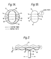
- stator 8 is shown schematically, with the female helical gear form shown in full lines and the path of the rotor shown in dotted lines.
- the rotor path is substantially coterminous with the stator form shown in full line.
- the stator form consists of two substantial semi-circular zones 10,12 and, on each side, two sets of straight line portions 14,14,16,16, the sets 14,16 meeting at the horizontal centre line 18 of the stator form.
- the semi circular portions 10,12 with the straight line portions 14,16 there is a sharp change in interference and experience has shown that there tends to be a leak path as is shown in the enlarged encircled portion in Figure 1B.
- the stator form is modified slightly so that the portions 14,16 essentially form a straight line.
- the dimensions of the rotor are chosen so that there is a significant interference as can be seen by the fact that the chain dotted indication of the rotor path 20 is shown, at least along the straight line portions 14,16, and a significant part of the semi-circular portions 10,12 of the stator forms, to be outside the stator form. The interference therefore diminishes progressively and smoothly from the straight line to the semi-circular portion.
- the interference at the locations of the major diameter are not significantly changed so that the interference at the locations at the minor diameter is significantly greater than the interference at the locations of the major diameter.
- the rotor 22 is shown as being sprayed with a coating, such as modified chromium oxide, by a plasma gun 24.
- a coating such as modified chromium oxide
- the gap of the rotor from the plasma gun is shown as a distance g. It will be appreciated that the gap at the troughs 28 of the rotor will be g + 2e. This tends to produce a greater thickness of coating at the troughs 28 than at the peaks 26.
- the base metal of the rotor is machined, with a construction according to the invention, so that in the region of the locations of major diameter, that is at the peaks 26, the thickness of the plasma coating is less and in the region of the locations of minor diameter, that is in the troughs, the thickness of the plasma coating is greater than in the remainder of the rotor, while allowing the interference to be significantly more at the locations of the minor diameter than at the locations of the major diameter.
- the ratio d/e of the minor diameter d to the eccentricity e is at least 8 and the ratio P/e of the pitch P to the eccentricity e is at least 17.5.
Abstract
Description
- The present invention relates to helical gear pumps. These comprise an outer stator member with a helical female gear formation of n starts, an inner rotor rotatable within said stator having a helical male gear formation of the same pitch of n±1 starts, means being provided to cause the rotor to rotate and orbit relative to the stator.
- Usually the rotor has n-1 starts.
- Traditionally the outer stator member is formed of a resilient, rubber like material and the rotor is formed of metal, usually steel. A typical example is shown in U S Patent 4773834. For the pump to operate satisfactorily, there must be a good seal at all times formed between the rotor and the stator so that the cavities formed therein, which progress through the pump, are effectively sealed between suction and discharge pressure. The seal is improved if the interference between the rotor and stator is increased, but this causes problems of requiring a greater drive power, heat generation and of wear on the two parts, particularly the stator.
- The helical gear formation of the rotor is such as to provide peaks and troughs in the rotor and experience has shown that wear on the rotor is normally initiated close to the rotor major diameter or peak. In order to reduce the amount of wear, it has been proposed to use a coating on the rotor of modified chromium oxide, this being applied by plasma coating. The use of modified chromium oxide as a coating medium results in a thicker deposition of the chromium oxide at the minor diameter or trough i.e. where it is least required. This is due to the complexity of the rotor geometry associated with the coating process which involves rotating the rotor about its normal axis, while applying the chromium oxide coating by means of a gun which traverses the length of the rotor parallel to the axis of rotation. As the rotor is rotated, the peripheral speed at the peaks will be higher than at the troughs. Furthermore, as the plasma torch or gun traverses along the length of the rotor, the distance or "gun gap" g between the gun and the rotor varies between g and g+2e, where e is the eccentricity of the rotor.
- The combination of varying peripheral speed and varying "gun gap" g lead to an uneven distribution of the coating. Consequently, it has been found that with a conventional rotor, in which the ratio d/e = 5 and P/e = 12.5, (where d is the minor diameter, e is the eccentricity and P is the rotor pitch), the coating thickness ratio between the minor diameter and the major diameter (the trough and the peak) has been found to be in excess of 1.5:1. This has two disadvantages. Firstly there is an unnecessary coating of the rotor at the minor diameter and secondly there is a risk of overcoating at the minor diameter, bearing in mind chromium oxide has a maximum thickness after which it peels off, that is its integrity of coating is reduced.
- It is now proposed, according to the present invention, to provide a helical gear pump comprising an outer stator member with a helical female gear formation of two starts, an inner rotor rotatable within said stator and having a helical male gear formation of the same pitch of one start, and means to cause said rotor to rotate and orbit relative to said stator, the rotor having a major diameter D, a minor diameter d, a pitch P and an eccentricity e, the shape of the helical female gear formation of the stator consisting of two semi-circular cross section-portions joined by two straight line portions, wherein the interference between the rotor and the stator is arranged to be such that the interference is significantly more at the locations of the minor diameter d than at the locations of the major diameter D, and wherein interference with the rotor diminishes progressively between the straight line and the semi-circular cross-section portions of the helical female gear formation of the stator.
- It has been found that if there is too much interference at the major diameter the capacity of the pump is reduced, largely because the size of the cavities formed between the rotor and stator is reduced by the larger diameter rotor. Equally important, however, if there is too much interference at the major diameter the power requirement is increased. The provision of a greater interference at the minor diameter has less effect in both of these connections and ensures that a good seal is produced thereby improving the efficiency of the pump.
- In the prior known constructions the shape of the cross-section of the helical female formation of the stator are formed by parts which are slightly greater than semi-circles and by two pairs of straight lines which taper slightly inwardly. The constructions are such that a sharp change in interference occurs where the straight lines meet the part circular portions, which adds to the problems indicated above. These problems are overcome by the structure of the invention.
- In a preferred construction, the interference at the location of the minor diameter d is considerably greater than the interference at the locations of the major diameter and the ratio d/e of the minor diameter d to eccentricity e is at least 8.
- Advantageously the ratio P/e of the rotor pitch P to the eccentricity e is at least 17.5.
- As indicated earlier, improved results can be achieved in pumps of this type if the metal of the rotor is plasma coated with a coating of modified chromium oxide. Advantageously with the structure of the present invention, the base metal of the rotor, prior to plasma coating, is machined so that in the region of the location of major diameter D, the thickness of the plasma coating is less and in the region of the locations of minor diameter d, the thickness of the plasma coating is greater than in the remainder of the rotor, while allowing the interference to be significantly more at the locations of the minor diameter d than at the locations of the major diameter D.
- In order that the present invention may be more readily understood, the following description is given, merely by way of example, reference being made to the accompanying drawing in which:-
- Figure 1A is a cross sectional schematic view showing the stator form and rotor path of one embodiment of helical gear pump according to the invention;
- Figure 1B is a similar view of a conventional pump;
- Figure 2 is a schematic side elevation showing the coating of a rotor according to the invention;
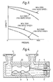
- Figure 3 is a graph showing the relationship between capacity and pressure of the convention pump and a pump according to the present invention; and
- Figure 4 is a cross-section through the pump.
- The pump illustrated in Figure 4 includes a casing 1 having an inlet 2 and an
outlet 3. Adrive shaft 4, which may be of the conventional rigid or flexible type, passes through abulkhead 5 via a bearing and/orseal assembly 6. Astator 8 is secured in the casing 1 and includes a two start femalehelical gear formation 9. Arotor 22 having a one start male helical gear formation 11 is driven by a motor (not shown) and driveshaft 4 to rotate and orbit in thestator 8. - Referring now to Figure 1A and 1B, the
stator 8 is shown schematically, with the female helical gear form shown in full lines and the path of the rotor shown in dotted lines. In the conventional structure of Figure 1B, the rotor path is substantially coterminous with the stator form shown in full line. The stator form consists of two substantialsemi-circular zones straight line portions sets horizontal centre line 18 of the stator form. At the junction of the semicircular portions straight line portions - With the structure according to the present invention, the stator form is modified slightly so that the
portions rotor path 20 is shown, at least along thestraight line portions semi-circular portions - On the other hand, however, the interference at the locations of the major diameter are not significantly changed so that the interference at the locations at the minor diameter is significantly greater than the interference at the locations of the major diameter.
- If reference is now made to Figure 2 of the drawings it will be seen that the
rotor 22 is shown as being sprayed with a coating, such as modified chromium oxide, by aplasma gun 24. At the vicinities of the peaks of 26 of the rotor the gap of the rotor from the plasma gun is shown as a distance g. It will be appreciated that the gap at thetroughs 28 of the rotor will be g + 2e. This tends to produce a greater thickness of coating at thetroughs 28 than at thepeaks 26. Therefore the base metal of the rotor is machined, with a construction according to the invention, so that in the region of the locations of major diameter, that is at thepeaks 26, the thickness of the plasma coating is less and in the region of the locations of minor diameter, that is in the troughs, the thickness of the plasma coating is greater than in the remainder of the rotor, while allowing the interference to be significantly more at the locations of the minor diameter than at the locations of the major diameter. - In this way optimum coating can be achieved without there being any fear of the integrity of the coating with the base metal being broken down and yet the desired interference which is greater at the locations of minor diameter than at the locations of the major diameter can also be arrived at.
- In a preferred arrangement, the ratio d/e of the minor diameter d to the eccentricity e is at least 8 and the ratio P/e of the pitch P to the eccentricity e is at least 17.5.
- If one now looks at Figure 3, one will see that the pressure/capacity curve of the pump according to the invention is shown in full line and the corresponding curve for a conventional pump of the same rating is shown in chained dotted lines. It will be seen that firstly there is a greater capacity at all times for the same pressure throughout the whole range of pressure both at the minimum rated speed of the pump and at the maximum rated speed and that there is a lesser drop off in the capacity as the pressure increases from minimum to maximum throughout the speed range of the pump. As can be seen from the comparison of the stator forms, the new form has eliminated the leak paths and this improves the performance of the rotor/stator combination and also prevents abrasive particles becoming trapped in the seal line where they potentially can cause more damage to the rotor.
- Wear tests with chromium oxide coated rotors having d/e ratio of 8 and P/e ratio of 17.5 have been extensively tested alongside hard chrome plated rotors having a more orthodox geometry. These wear tests have shown a significant increase in life in favour of chromium oxide coated rotors.
- With a conventional rotor geometry, i.e. d/e = 5 and P/e = 12.5, the coating thickness ratio of the minor:major (trough:peak) has been found to be in excess of 1.5:1. The geometry has according to the invention, in which d/e = 8 and P/e = 17.5 substantially reduces this ratio to 1.3:1 this results in the two advantages that it reduces the unnecessary coating at the minor diameter and reduces the risk of over coating at the major diameter which would result in the coating peeling off.
Claims (5)
Applications Claiming Priority (2)
| Application Number | Priority Date | Filing Date | Title |
|---|---|---|---|
| GB8902230 | 1989-02-01 | ||
| GB8902230A GB2228976B (en) | 1989-02-01 | 1989-02-01 | Helical gear pump |
Publications (2)
| Publication Number | Publication Date |
|---|---|
| EP0381413A2 true EP0381413A2 (en) | 1990-08-08 |
| EP0381413A3 EP0381413A3 (en) | 1990-12-05 |
Family
ID=10650971
Family Applications (1)
| Application Number | Title | Priority Date | Filing Date |
|---|---|---|---|
| EP19900300894 Withdrawn EP0381413A3 (en) | 1989-02-01 | 1990-01-29 | Helical gear pump |
Country Status (4)
| Country | Link |
|---|---|
| EP (1) | EP0381413A3 (en) |
| FI (1) | FI900500A0 (en) |
| GB (1) | GB2228976B (en) |
| NO (1) | NO172200C (en) |
Cited By (4)
| Publication number | Priority date | Publication date | Assignee | Title |
|---|---|---|---|---|
| EP0627556A1 (en) * | 1993-03-18 | 1994-12-07 | Praxair S.T. Technology, Inc. | Carbide or boride coated rotor for a positive displacement motor or pump |
| EP0985826A1 (en) * | 1998-09-09 | 2000-03-15 | Mono Pumps Limited | Progressing cavity pump |
| WO2004081347A1 (en) * | 2003-03-11 | 2004-09-23 | Obschestvo S Ogranichennoi Otvetstvennostyu Firma Radius-Servis | Rotor for a helical hydraulic unit |
| DE102017104768A1 (en) | 2017-03-07 | 2018-09-13 | Seepex Gmbh | Cavity Pump |
Families Citing this family (2)
| Publication number | Priority date | Publication date | Assignee | Title |
|---|---|---|---|---|
| US5498142A (en) * | 1995-05-30 | 1996-03-12 | Kudu Industries, Inc. | Hardfacing for progressing cavity pump rotors |
| CN105240269A (en) * | 2014-06-26 | 2016-01-13 | 水利部科技推广中心 | Double-end U-type thread divided spiral micro-nano bubble device |
Citations (5)
| Publication number | Priority date | Publication date | Assignee | Title |
|---|---|---|---|---|
| DE1553148A1 (en) * | 1966-03-12 | 1969-07-03 | Netzsch Maschinenfabrik | Runner for screw pumps |
| DE1553146A1 (en) * | 1965-09-16 | 1970-02-05 | Netzsch Maschinenfabrik | Runner for screw pumps |
| DE2017620B2 (en) * | 1970-04-13 | 1976-04-22 | Gummi-Jäger KG GmbH & Cie, 3000 Hannover | Eccentric worm pump having resilient stator - with rectangular laterally rounded-section rotor chamber of lesser width than rotor section |
| GB1542786A (en) * | 1976-03-09 | 1979-03-28 | Mec Et De Metallurg Sa Soc Gen | Moineau-type screw pump stators |
| US4773834A (en) * | 1983-08-16 | 1988-09-27 | Patrick J. Quinn | Progressive cavity pump |
Family Cites Families (2)
| Publication number | Priority date | Publication date | Assignee | Title |
|---|---|---|---|---|
| GB629454A (en) * | 1947-11-04 | 1949-09-20 | Fmc Corp | Improvements in gear type pumps |
| BE651030A (en) * | 1963-07-25 |
-
1989
- 1989-02-01 GB GB8902230A patent/GB2228976B/en not_active Expired - Fee Related
-
1990
- 1990-01-29 EP EP19900300894 patent/EP0381413A3/en not_active Withdrawn
- 1990-01-31 FI FI900500A patent/FI900500A0/en not_active IP Right Cessation
- 1990-01-31 NO NO900446A patent/NO172200C/en unknown
Patent Citations (5)
| Publication number | Priority date | Publication date | Assignee | Title |
|---|---|---|---|---|
| DE1553146A1 (en) * | 1965-09-16 | 1970-02-05 | Netzsch Maschinenfabrik | Runner for screw pumps |
| DE1553148A1 (en) * | 1966-03-12 | 1969-07-03 | Netzsch Maschinenfabrik | Runner for screw pumps |
| DE2017620B2 (en) * | 1970-04-13 | 1976-04-22 | Gummi-Jäger KG GmbH & Cie, 3000 Hannover | Eccentric worm pump having resilient stator - with rectangular laterally rounded-section rotor chamber of lesser width than rotor section |
| GB1542786A (en) * | 1976-03-09 | 1979-03-28 | Mec Et De Metallurg Sa Soc Gen | Moineau-type screw pump stators |
| US4773834A (en) * | 1983-08-16 | 1988-09-27 | Patrick J. Quinn | Progressive cavity pump |
Cited By (7)
| Publication number | Priority date | Publication date | Assignee | Title |
|---|---|---|---|---|
| EP0627556A1 (en) * | 1993-03-18 | 1994-12-07 | Praxair S.T. Technology, Inc. | Carbide or boride coated rotor for a positive displacement motor or pump |
| EP0985826A1 (en) * | 1998-09-09 | 2000-03-15 | Mono Pumps Limited | Progressing cavity pump |
| US6220837B1 (en) | 1998-09-09 | 2001-04-24 | Mono Pumps Limited | Progressing cavity pump having a ratio of eccentricity, rotor diameter and stator lead |
| AU754641B2 (en) * | 1998-09-09 | 2002-11-21 | Mono Pumps Limited | Progressing cavity pump |
| WO2004081347A1 (en) * | 2003-03-11 | 2004-09-23 | Obschestvo S Ogranichennoi Otvetstvennostyu Firma Radius-Servis | Rotor for a helical hydraulic unit |
| DE102017104768A1 (en) | 2017-03-07 | 2018-09-13 | Seepex Gmbh | Cavity Pump |
| WO2018162360A1 (en) | 2017-03-07 | 2018-09-13 | Seepex Gmbh | Eccentric spiral pump |
Also Published As
| Publication number | Publication date |
|---|---|
| NO900446D0 (en) | 1990-01-31 |
| GB2228976A (en) | 1990-09-12 |
| GB8902230D0 (en) | 1989-03-22 |
| NO172200C (en) | 1993-06-16 |
| GB2228976B (en) | 1993-08-11 |
| FI900500A0 (en) | 1990-01-31 |
| NO900446L (en) | 1990-08-02 |
| EP0381413A3 (en) | 1990-12-05 |
| NO172200B (en) | 1993-03-08 |
Similar Documents
| Publication | Publication Date | Title |
|---|---|---|
| US5120204A (en) | Helical gear pump with progressive interference between rotor and stator | |
| US6220840B1 (en) | Wall shape for scroll-type compressor vanes | |
| US4913619A (en) | Centrifugal pump having resistant components | |
| KR101029624B1 (en) | Internal gear pump and inner rotor of the pump | |
| JPH0141839B2 (en) | ||
| EP0381413A2 (en) | Helical gear pump | |
| US20010031202A1 (en) | Rotatory pump having a knobbed impeller wheel, and a knobbed impeller wheel therefor | |
| EP0565232B1 (en) | Liquid ring pumps with improved housing shapes | |
| JPS6161901A (en) | Female and male rotor for screw rotary machine and pair of spiral rotor | |
| WO2009101699A1 (en) | Turbomolecular pump | |
| JPH01163401A (en) | Scroll type machine | |
| KR100311239B1 (en) | Oil Pump Proter | |
| EP0937896B1 (en) | Electric fuel pump | |
| GB2351324A (en) | Regenerative pump impeller | |
| SU1441077A1 (en) | Screw-type rotors | |
| JP3701378B2 (en) | Screw rotor | |
| CN113236455A (en) | High-power-density electric fuel pump for multi-electric aviation auxiliary power device | |
| JPS60128983A (en) | Driven gear for rotary gear pump | |
| GB2049834A (en) | Rotor for a Rotary Pump | |
| RU2244169C2 (en) | Welded impeller of centrifugal pump | |
| US6422847B1 (en) | Screw rotor tip with a reverse curve | |
| JP2000291565A (en) | Internal gear pump equipped with sealing member inserted in addendum part, having no sickle-shaped member | |
| JP3377907B2 (en) | Fluid machinery | |
| WO2005047705A1 (en) | Vacuum screw pump | |
| JPH0299794A (en) | Eddy current type turbomachinery |
Legal Events
| Date | Code | Title | Description |
|---|---|---|---|
| PUAI | Public reference made under article 153(3) epc to a published international application that has entered the european phase |
Free format text: ORIGINAL CODE: 0009012 |
|
| AK | Designated contracting states |
Kind code of ref document: A2 Designated state(s): AT BE CH DE DK ES FR GB GR IT LI LU NL SE |
|
| PUAL | Search report despatched |
Free format text: ORIGINAL CODE: 0009013 |
|
| AK | Designated contracting states |
Kind code of ref document: A3 Designated state(s): AT BE CH DE DK ES FR GB GR IT LI LU NL |
|
| 17P | Request for examination filed |
Effective date: 19910604 |
|
| 17Q | First examination report despatched |
Effective date: 19920903 |
|
| STAA | Information on the status of an ep patent application or granted ep patent |
Free format text: STATUS: THE APPLICATION IS DEEMED TO BE WITHDRAWN |
|
| 18D | Application deemed to be withdrawn |
Effective date: 19940116 |