EP0381336A1 - Ceramic bearing - Google Patents
Ceramic bearing Download PDFInfo
- Publication number
- EP0381336A1 EP0381336A1 EP90300514A EP90300514A EP0381336A1 EP 0381336 A1 EP0381336 A1 EP 0381336A1 EP 90300514 A EP90300514 A EP 90300514A EP 90300514 A EP90300514 A EP 90300514A EP 0381336 A1 EP0381336 A1 EP 0381336A1
- Authority
- EP
- European Patent Office
- Prior art keywords
- sliding
- ring
- ceramic
- bearing
- inner ring
- Prior art date
- Legal status (The legal status is an assumption and is not a legal conclusion. Google has not performed a legal analysis and makes no representation as to the accuracy of the status listed.)
- Granted
Links
- 239000000919 ceramic Substances 0.000 title claims abstract description 45
- 238000005096 rolling process Methods 0.000 abstract description 12
- 239000000463 material Substances 0.000 description 9
- 239000002184 metal Substances 0.000 description 5
- 229910052751 metal Inorganic materials 0.000 description 5
- 229910002077 partially stabilized zirconia Inorganic materials 0.000 description 5
- RYGMFSIKBFXOCR-UHFFFAOYSA-N Copper Chemical compound [Cu] RYGMFSIKBFXOCR-UHFFFAOYSA-N 0.000 description 4
- XEEYBQQBJWHFJM-UHFFFAOYSA-N Iron Chemical compound [Fe] XEEYBQQBJWHFJM-UHFFFAOYSA-N 0.000 description 4
- PNEYBMLMFCGWSK-UHFFFAOYSA-N aluminium oxide Inorganic materials [O-2].[O-2].[O-2].[Al+3].[Al+3] PNEYBMLMFCGWSK-UHFFFAOYSA-N 0.000 description 4
- 229910052802 copper Inorganic materials 0.000 description 4
- 239000010949 copper Substances 0.000 description 4
- 229910052574 oxide ceramic Inorganic materials 0.000 description 4
- 239000011224 oxide ceramic Substances 0.000 description 4
- 238000000034 method Methods 0.000 description 3
- 229910052742 iron Inorganic materials 0.000 description 2
- 229910001018 Cast iron Inorganic materials 0.000 description 1
- 206010052804 Drug tolerance Diseases 0.000 description 1
- 229910000831 Steel Inorganic materials 0.000 description 1
- 229910001361 White metal Inorganic materials 0.000 description 1
- 230000002411 adverse Effects 0.000 description 1
- 229910045601 alloy Inorganic materials 0.000 description 1
- 239000000956 alloy Substances 0.000 description 1
- 238000010276 construction Methods 0.000 description 1
- 230000003247 decreasing effect Effects 0.000 description 1
- 230000006866 deterioration Effects 0.000 description 1
- 229910003460 diamond Inorganic materials 0.000 description 1
- 239000010432 diamond Substances 0.000 description 1
- 230000000694 effects Effects 0.000 description 1
- 238000003754 machining Methods 0.000 description 1
- 239000000843 powder Substances 0.000 description 1
- 230000000630 rising effect Effects 0.000 description 1
- 239000010959 steel Substances 0.000 description 1
- 230000003746 surface roughness Effects 0.000 description 1
- 239000010969 white metal Substances 0.000 description 1
Images

Classifications
-
- F—MECHANICAL ENGINEERING; LIGHTING; HEATING; WEAPONS; BLASTING
- F16—ENGINEERING ELEMENTS AND UNITS; GENERAL MEASURES FOR PRODUCING AND MAINTAINING EFFECTIVE FUNCTIONING OF MACHINES OR INSTALLATIONS; THERMAL INSULATION IN GENERAL
- F16C—SHAFTS; FLEXIBLE SHAFTS; ELEMENTS OR CRANKSHAFT MECHANISMS; ROTARY BODIES OTHER THAN GEARING ELEMENTS; BEARINGS
- F16C33/00—Parts of bearings; Special methods for making bearings or parts thereof
- F16C33/02—Parts of sliding-contact bearings
- F16C33/04—Brasses; Bushes; Linings
- F16C33/043—Sliding surface consisting mainly of ceramics, cermets or hard carbon, e.g. diamond like carbon [DLC]
-
- F—MECHANICAL ENGINEERING; LIGHTING; HEATING; WEAPONS; BLASTING
- F16—ENGINEERING ELEMENTS AND UNITS; GENERAL MEASURES FOR PRODUCING AND MAINTAINING EFFECTIVE FUNCTIONING OF MACHINES OR INSTALLATIONS; THERMAL INSULATION IN GENERAL
- F16C—SHAFTS; FLEXIBLE SHAFTS; ELEMENTS OR CRANKSHAFT MECHANISMS; ROTARY BODIES OTHER THAN GEARING ELEMENTS; BEARINGS
- F16C17/00—Sliding-contact bearings for exclusively rotary movement
- F16C17/10—Sliding-contact bearings for exclusively rotary movement for both radial and axial load
-
- F—MECHANICAL ENGINEERING; LIGHTING; HEATING; WEAPONS; BLASTING
- F16—ENGINEERING ELEMENTS AND UNITS; GENERAL MEASURES FOR PRODUCING AND MAINTAINING EFFECTIVE FUNCTIONING OF MACHINES OR INSTALLATIONS; THERMAL INSULATION IN GENERAL
- F16C—SHAFTS; FLEXIBLE SHAFTS; ELEMENTS OR CRANKSHAFT MECHANISMS; ROTARY BODIES OTHER THAN GEARING ELEMENTS; BEARINGS
- F16C17/00—Sliding-contact bearings for exclusively rotary movement
- F16C17/12—Sliding-contact bearings for exclusively rotary movement characterised by features not related to the direction of the load
- F16C17/18—Sliding-contact bearings for exclusively rotary movement characterised by features not related to the direction of the load with floating brasses or brushing, rotatable at a reduced speed
-
- F—MECHANICAL ENGINEERING; LIGHTING; HEATING; WEAPONS; BLASTING
- F16—ENGINEERING ELEMENTS AND UNITS; GENERAL MEASURES FOR PRODUCING AND MAINTAINING EFFECTIVE FUNCTIONING OF MACHINES OR INSTALLATIONS; THERMAL INSULATION IN GENERAL
- F16C—SHAFTS; FLEXIBLE SHAFTS; ELEMENTS OR CRANKSHAFT MECHANISMS; ROTARY BODIES OTHER THAN GEARING ELEMENTS; BEARINGS
- F16C2300/00—Application independent of particular apparatuses
- F16C2300/20—Application independent of particular apparatuses related to type of movement
- F16C2300/22—High-speed rotation
-
- Y—GENERAL TAGGING OF NEW TECHNOLOGICAL DEVELOPMENTS; GENERAL TAGGING OF CROSS-SECTIONAL TECHNOLOGIES SPANNING OVER SEVERAL SECTIONS OF THE IPC; TECHNICAL SUBJECTS COVERED BY FORMER USPC CROSS-REFERENCE ART COLLECTIONS [XRACs] AND DIGESTS
- Y10—TECHNICAL SUBJECTS COVERED BY FORMER USPC
- Y10S—TECHNICAL SUBJECTS COVERED BY FORMER USPC CROSS-REFERENCE ART COLLECTIONS [XRACs] AND DIGESTS
- Y10S384/00—Bearings
- Y10S384/90—Cooling or heating
- Y10S384/901—Floating bushing
Definitions
- This invention relates to a ceramic bearing comprising a ceramic outer ring, a ceramic inner ring, and a ceramic sliding ring which is fitted between a ceramic outer ring and a ceramic inner ring.
- a bearing such as a sliding bearing or a rolling bearing is commonly used.
- the rolling bearing comprise rolling members such as balls, rollers, or needles which are positioned between an outer ring fitted into a housing provided in a mechanical frame and an inner ring into which a rotation shaft is installed.
- the rolling bearing are classfied into ball, rolling, and needle bearings according to the type of a rolling member used ( Japanese Patent Publication No.49-41231 ).
- deep-groove type, angular ball type, and taper-roller type bearings are used as a bearing capable of supporting a shaft to which a radial and thrust loads are applied at the same time.
- sliding bearings include a steel, cast iron, or copper support on which a white metal layer is laminated and held in a predetermined dimmension by machining, or copper or gun-metal support which an oil-impregnated alloy is laminated on or embedded into.
- a sliding bearing having a sleeve-shaped support is used as a bearing for supporting radial load ( Japanese Patent Pablication No. 49-18885 ).
- a sliding bearing whose metal support is formed in disk-shape also is used to support a thrust load ( Japanese Patent Pablication No.49-678 ).
- a load per unit area which the sliding bearing can support depends on a sort of material of the bearing.
- iron or copper-based metal is employed as a material, however, the allowable pressure per unit area is smaller than that of ceramics, therefore a larger pressured area is needed to support a large load, and the sliding bearing gives rise to another problem that its size tends to become larger.
- Another object of the present invention is to provide a bearing having a small number of components by utilizing a ceramic inner ring, a ceramic outer ring, and a ceramic sliding ring.
- the ceramic bearing of the present invention has a feature that a ceramic sliding ring is fitted between a ceramic outer ring and a ceramic inner ring.
- the ceramic sliding ring (to be called “ sliding ring” ) is positioned between the ceramic outer ring ( to be called “outer ring”) and the ceramic inner ring ( to be called “inner ring”), thereby, a load which is applied to a shaft installed in the inner ring is transmitted from the inner ring, through the sliding ring, to the outer ring, and is supported.
- each ring is formed of ceramics, a compressive strength of each ring is higher than that of iron or copper-based metal, the allowable load of the bearing therefore can be provided larger than that of a conventional sliding ring.
- a sliding surface between the inner ring and outer ring, there are formed a sliding surface between an outside circumferece of the inner ring and an inside circumference, and another sliding surface between an outside circumference of the sliding ring and an inside circumference of the outer ring.
- the bearing comprises a plurality of sliding rings fitted between the outer and inner rings
- sliding surfaces corresponding to the number of fitted sliding rings can be formed, and thus it will be possible to make a sliding speed on each sliding surface lower and to reduce heat and wear on each sliding surface.
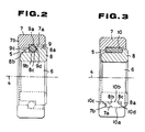
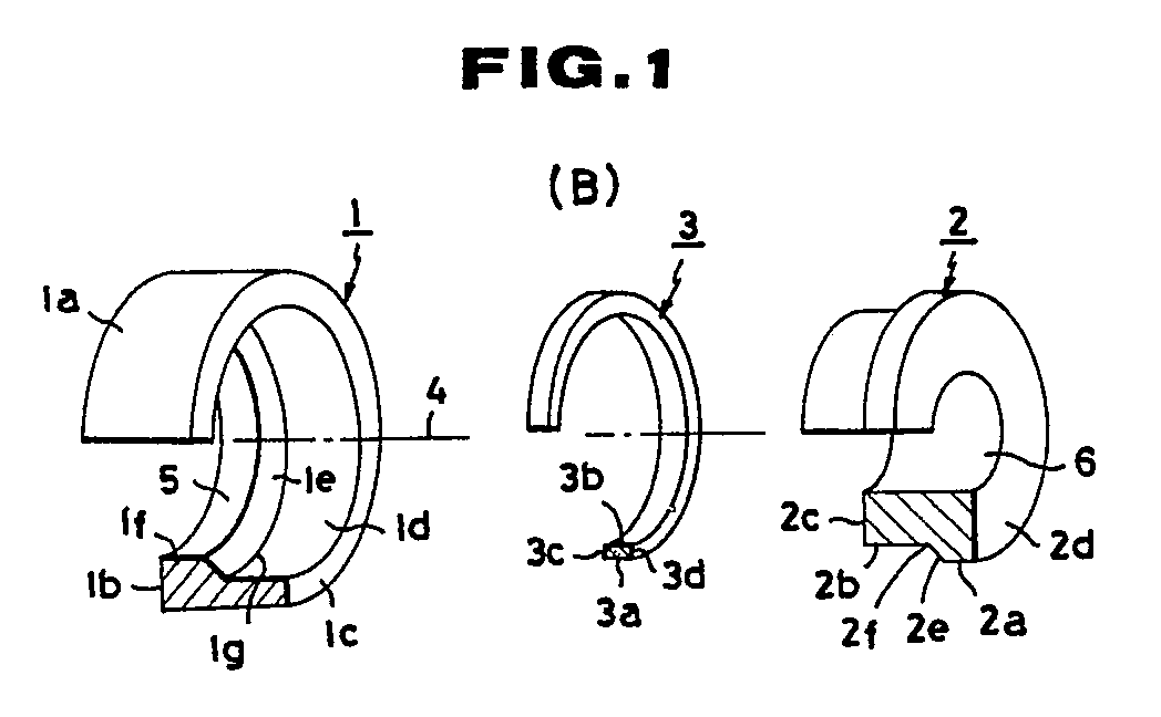
- a bearing comprises an outer ring 1, an inner ring 2, and a sliding ring 3 which is fitted between the outer ring 1 and the inner ring 2.
- the outer ring 1 is produced through the process steps that an oxide ceramics material based on Partially-Stabilized-Zirconia ( to be called "PSZ” hereinafter ) or alumina is charged into a mold and is press-formed, and a molded compact ring is sintered at 1500°C to 1600°C.
- PSZ Partially-Stabilized-Zirconia
- a form of the outer ring 1 is formed with a cylindrical outside circumference portion 1a and end faces 1b and 1c.
- the outside circumference portion 1a is a fit-into surface for being installed in a housing which is provided in a machine. To make a precise fitting, the outside circumference portion 1a is parallel to an axial center 4 of the outer ring 1 and holds a predetermined diameter and its tolerance.
- the end face 1b has a through bore 5.
- the inside circumference of the outer ring 1 includes a sliding surface 1d which has a predetermined length in the axial direction from the end face 1c.
- the sliding surface 1d is in cylindrical-shape and parallel to the axial center4.
- a tapered surface 1e is formed between the sliding surface 1d and the through bore 5, and the outer ring 1 incorporates a circumferential protrusion 1f on the inside cicumference on the end face 1b side.
- the inner ring 2 is produced through the process steps that an oxide ceramics material of PSZ or alumina is charged into a mold and press-formed, and the moled compact ring is sintered at 1500°C to 1600°C.
- a form of an inner ring 2 is formed with a flange-shaped, circumferential protrusion 2a, a cylindrical sliding surface 2b, and an end face 2c and 2d, and a tapered surface 2e is formed between the sliding surface 2b and the flange-shaped, circumferential protrusion 2a.
- the inner ring 2 has a bore 6 which is in line with the axial center 4 and a shaft (not shown ) is fitted into the bore 6.
- the shaft-fitting bore 6 is provided for fitting the shaft to which a radial load, a thrust load, or the resultant load of said loads is applied, and is formed with a predetermined diameter held by its tolerance.
- the end face 2d also is provided as a face to which the thrust load is transmitted, in contact with an end face of the shaft.
- the sliding ring 3 is produced through the process steps that an oxide ceramics material of PSZ or alumina is charged into a mold and press-formed, and the molded compact ring is sintered at 1500°C to 1600°C.
- the sliding ring is formed in sleeve-shape, and the outside circumference of the sliding ring 3 is provided as a sliding surface 3a sliding in contact with the sliding surface 1d formed on the inside circumference of the outer ring 1.
- the sliding surface 3a holds a predetermined tolerance relative to the sliding surface 1d of the outer ring 1.
- the inside circumference of the sliding ring 3 also is provided as a silding surface 3b sliding in contact with the sliding surface 2b on the outside circumference of the inner ring 2, and the sliding surface 3b holds a predetermined tolerance relative to the sliding surface 2b on the inner ring 2.
- An end face 3c of the sliding ring 3 is formed so that the end face 3c abuts a tapered surface 1e or a neck portion 1g of said tapered surface 1e on the inside circumference of the outer ring 1.
- An end face 3d of the sliding ring 3 is also formed so that the end face 3d may abut a tapered surface 2e or a neck portion 2f of said tapered surface 2e on the outside circumference of the inner ring 2.
- a journal portion (not shown ) of the shaft is fitted into the shaft-fitting bore 6 in the inner ring 2, and a radial load applied to the shaft is transmitted from the inner ring 2, through the sliding ring 3, to the outer ring 1.
- a thrust load is applied to the shaft, a stepped diameter portion of the shaft abuts the end face 2d of the inner ring 2, and thereby the thrust load is transmitted from the inner ring 2, through the sliding ring 3, to the outer ring 1.
- the inner ring 2 rotates at the same speed as that of the shaft, and said load is transmitted from the neck portion 2f of the tapered surface 2e on the outside circumference of said inner ring 2, to the end face 3d of sliding ring 3, and slide will take place between the neck portion 2f and the end face 3d.
- a high-speed rotation shaft can be supported depending on an increment of an area of sliding surface, that is, the high-speed rotating shaft can be supported with the ceramic bearing of the embodiment.
- Fig.2 is a sectional view of the second embodiment of the present invention, which relates to a bearing in which a sliding ring having a circular section is fitted between an outer ring 7 and an inner ring 8.
- the same portion as that of the first embodiment and the portion having the same function as that of the first are marked with the same numreals, and a description on the portions is omitted (the same to be omitted hereinafter).
- the inside circumference of the outer ring 7 includes a through bore 5 and a sliding surface 7a being parallel to an axial center 4. Said sliding 7a has a diameter of larger than that of the through bore 5. Thus, a circumferential protrusion 7b is formed between the through bore 5 and the sliding surface 7b. A height of said protrusion 7b is slightly larger than half of a thickness of the sliding ring 9 to be described later, that is, than a circularly sectional radius of that.
- a riser portion 8c is formed between said flange-shaped protrusion 8a and a silding surface 8b, and a height of said riser 8c is slightly higher than half of thickness of the siliding ring 9, that is, than a circularly sectional radius of said sliding ring 9.
- the sliding ring 9 has a circular section of the predetermined radius, and each sliding portion 9a to 9d refers to an outside circumferential portion, an inside circumferential portion,or each of end faces respectively.
- said bearing comprising the outer ring 7, the inner ring 8, and the sliding ring 9,the silding portion 9a on the outside circumference of the sliding ring 9 is in contact with the sliding surface 7a on the inside cicumference of the outer ring 7, likewise, the sliding portion 9a is in contact with the sliding surface 8b on the outside circumference of the inner ring 8, and sliding portion 9c is in contact with a riser portion of the protrusion 7b on the inside circumferenceof the outer ring 7, and the sliding portion 9d is in contact with the riser portion 8c on the outside circumference of the inner ring 8, and thus each silding surface is formed.
- said bearing is constructed so that is capable of supporting radial and thrust loads applied tothe shaft fitted into the inner ring 8.
- Fig.3 is a sectional view of a bearing of the third embodiment of the invention, which relates to a bearing which a sliding ring 10 having a elliptic section is fitted between an outer ring 7 and an inner ring 8.
- a sliding surface 10a being in contact with a sliding surface 7a on an inside circumferential surface of the outer ring 7, and formed on an inside circumferential surface of the sliding ring 10 a sliding surface 10b being in contact with a sliding surface 8b on an outside circumferential surface of the inner ring 8.
- Bothof the ends an axial cross-section of the silding ring 10 is in round-shaped, and one of the ends is a sliding surface 10c being in contact with a riser portion of the protrusion 7b of the outer ring 7, and another end is a sliding surface 10d being in contact with a riser portion 8c of the inner ring 8.
- the bearing of this embodiment can support radial and thrust loads which are applied to the shaft fitted into the inner ring 8.
- the radial pressured- area may be taken larger.
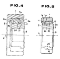
- Fig.4 is a sectinal view of a bearing related to the fourth embodiment of the present invention, which relates to a bearing which a sliding ring 11 having a L-shaped section is fitted into the outer ring 7 shown in Fig.2 and the inner ring 2 shown in Fig.1.
- the bearing of this embodiment is capable of employing the whole of the silding surface 2b formed the outside circumference of the inner ring 2 and the outside circumferential of the flange- shaped protrusion 2a as a pressured area, and thus can support a large radial load.
- Fig.5 is a sectional view of a bearing related to the fifth embodiment of the present invention, which relates to a bearing which a sliding 12 having a Z-shaped section is fitted between the outer ring 1 and inner ring 2 shown in Fig.1.
- the bearing of this embodiment can employ the whole of a sliding surface 2b formed on the outside circumference of the inner ring 2 and the outside circumferential surface of the flange-shaped protrusion 2a as a load-pressured area. Thereby, a large load can be supported by this type of bearing.
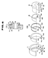
- Fig.6(A) and (B) are drawings illustrating a bearing related to the sixth embodiment of the present invention, which relates to a bearing which a plurality of sliding rings are fitted between the outer ring 1 and inner ring 2.
- the outer ring 1 and inner ring 2 are formed in the same manner as the embodiment shown in Fig.1 is.
- Sliding rings 14 and 15 being held by a retainer 13 are fitted between said outer ring 1 and inner ring 2.
- These sliding rings and the retainer 13 are produced from the same material as that of the sliding ring 3 shown in Fig.1, in the same manner as said sliding ring 3 is.
- the sliding ring 14 is formed into sleeve-shape, its outside circumferential surface is formed as a sliding surface 14 being in contact with a sliding surface 1d formed on the inside circumference of the outer ring 1, and its inside circumferential surface is formed as a sliding surface 14b being in contact with a sliding surface 13a of the retainer 13.
- One end face of the sliding ring 14 is formed as a sliding face 14c being in contact with a neck portion 1g of a tapered surface 1e onthe inside circumference of the outer ring 1, and another end face is formed as a sliding surface 14d being in contact with a flange 13d of the retainer 13, and the sliding ring 14 is rotatably fitted outside the retainer 13.
- the sliding ring 15 is formed into sleeve-shape, its inside circumferential surface is formed as a sliding surface 15a being in contact with a sliding surface 2b on the outside circumference of the inner ring 2, and its outside circumferential surface is formed as a sliding surface 15b being in contact with an inside circumferential surface 13b of the retainer 13.
- One end face of the sliding ring 15 is formed as a sliding face 15c being in contact with a flange 13c of the retainer 13, and another end face is formed as a sliding face 15d being in contact with a neck portion 2f of a tapered surface 2e formed in the inner ring 2, and the sliding ring 15 is rotatably fitted outside the retainer 13.
- the retainer 13 can be formed by melt-bonding flange portions 13c and 13d on both ends of a sleeve-shaped ring, or by melt-bonding a flange on one end of T-shaped formed ring.
- each sliding surface of the outer ring, inner ring, and sliding ring can be additionally finished by lapping, if neccessary.
- the lapping may be seperately made on each of outer, inner, and sliding rings, or may be selectively made by rubbing those rings together with abrasive such as diamond powder poured on the rings.
- abrasive such as diamond powder poured on the rings.
- each rings of the embodiments is formed from ceramics material , heat affects the bearing less than it is of metal. That is, A coefficient of thermal expansion of ceramics is 3 to 11 10 /°C, and an excessive stress will not be produced by thermal expansion, and a thermal deterioration also never occures.
Abstract
Description
- This invention relates to a ceramic bearing comprising a ceramic outer ring, a ceramic inner ring, and a ceramic sliding ring which is fitted between a ceramic outer ring and a ceramic inner ring.
- Up to the present, when installing a rotating shaft, a bearing such as a sliding bearing or a rolling bearing is commonly used.
- The rolling bearing comprise rolling members such as balls, rollers, or needles which are positioned between an outer ring fitted into a housing provided in a mechanical frame and an inner ring into which a rotation shaft is installed. The rolling bearing are classfied into ball, rolling, and needle bearings according to the type of a rolling member used ( Japanese Patent Publication No.49-41231 ).
- Among these bearings, deep-groove type, angular ball type, and taper-roller type bearings are used as a bearing capable of supporting a shaft to which a radial and thrust loads are applied at the same time.
- Some of the sliding bearings include a steel, cast iron, or copper support on which a white metal layer is laminated and held in a predetermined dimmension by machining, or copper or gun-metal support which an oil-impregnated alloy is laminated on or embedded into.
- A sliding bearing having a sleeve-shaped support is used as a bearing for supporting radial load ( Japanese Patent Pablication No. 49-18885 ). In addition, a sliding bearing whose metal support is formed in disk-shape also is used to support a thrust load ( Japanese Patent Pablication No.49-678 ).
- Said rolling and sliding bearings are standarized, many of them are commonly available and have its feature respectively. In practical use, these bearings are designed to be suited to its use in consideration of its feature.
- However, even said sliding and rolling bearings still have some difficult problems.
- For example, the following problems arise from a rolling bearing: A flaking caused from rolling fatigue will limit its service life and its heat resistance is low, additionaly, the cost may rise due to a relatively larger number of components, and rolling members being worn will cause a noise.
- In sliding bearings, since an outside circumference of a journal portion of a shaft as well as an inside circumference support a load applied to the shaft in close contact with each other, a sliding friction on contacting surfaces will generates heat. The amount of generated heal depends on a load applied to a shaft and a sliding speed. The amount of heat increases with rising speed, and causes the thermal expansion of the shaft and bearing, and thus, it is likely to have an adverse effect on a smooth rotation of the shaft. In addition, as the journal portion of the shaft and the inside circumfernce of the bearing also slide in close contact with each other, wear results on the shaft and bearing, and the wear also is possible to obstruct the smooth rotation of the shaft.
- Otherwise, in a silding bearing, a load per unit area which the sliding bearing can support depends on a sort of material of the bearing. In conventional silding bearing, iron or copper-based metal is employed as a material, however, the allowable pressure per unit area is smaller than that of ceramics, therefore a larger pressured area is needed to support a large load, and the sliding bearing gives rise to another problem that its size tends to become larger.
- Besides, in a sliding bearing, when supporting a shaft to which a thrust and radial loads are applied at the same time, there exist other problems that a sleeve-shaped radial bearing and a disk-shaped thrust bearing must be utilized in combination, or a bearing suitable to its use must be designed each time.
- It is an object of the present invention to provide a sliding bearing capable of supporting a shaft which a large load is applied to and rotates at a high speed.
- Another object of the present invention is to provide a bearing having a small number of components by utilizing a ceramic inner ring, a ceramic outer ring, and a ceramic sliding ring.
- Thus, to achieve these objects, the ceramic bearing of the present invention has a feature that a ceramic sliding ring is fitted between a ceramic outer ring and a ceramic inner ring.
- As above described on the present invention, the ceramic sliding ring ( to be called " sliding ring" ) is positioned between the ceramic outer ring ( to be called "outer ring") and the ceramic inner ring ( to be called "inner ring"), thereby, a load which is applied to a shaft installed in the inner ring is transmitted from the inner ring, through the sliding ring, to the outer ring, and is supported. As above described, since each ring is formed of ceramics, a compressive strength of each ring is higher than that of iron or copper-based metal, the allowable load of the bearing therefore can be provided larger than that of a conventional sliding ring.
- In addition, between the inner ring and outer ring, there are formed a sliding surface between an outside circumferece of the inner ring and an inside circumference, and another sliding surface between an outside circumference of the sliding ring and an inside circumference of the outer ring. Thereby, when the inner ring rotates at the same rotating speed as that of the fitted into the inner ring, the sliding ring rotates at a rotating speed of lower than that of the inner ring, follwing the inner ring in rotating. Thus, the relative rotating speed of the inner ring to the outer ring can be shared between these sliding surfaces. A sliding speed on each sliding surface is lower than the speed when the outer ring and inner ring rotate in direct contact with each other, and heat and wear produced on each sliding surface will be reduced. When the bearing is designed, providing the sliding speed on each sliding surface as a design standard, the bearing can support a shaft rotating at a higher speed.
- Moreover, as no sliding takes place between the inner ring with the shaft journal being fitted and the shaft, the shaft will never wear down.
- Additionally, when the bearing comprises a plurality of sliding rings fitted between the outer and inner rings, sliding surfaces corresponding to the number of fitted sliding rings can be formed, and thus it will be possible to make a sliding speed on each sliding surface lower and to reduce heat and wear on each sliding surface.
-
- Fig.1(A) is a sectional view illustrating the bearing of the first embodiment of the present invention.
- Fig.1(B) is an exploded perspective view illustrating components of the bearing of the first embodiment of the present invention.
- Fig.2 is a sectional view illustrating the bearig of the second embodiment of the present invention.
- Fig.3 is a sectional view illustrating the bearing of the third embodiment of the present invention.
- Fig. 4 is a sectional view illustrating the bearing of the fourth embodiment of the present invention.
- Fig.5 is a sectional view illustrating the bearing of the fifth embodiment of the present invention.
- Fig.6(A)is a sectional view illustrating the bearing of the sixth embodiment of the present invention.
- Fig.6(B) is an exploded perspective view illustrating components of the bearing of the sixth embodiment of present invention.
- In Fig.1(A)and (B), a bearing comprises an
outer ring 1, aninner ring 2, and asliding ring 3 which is fitted between theouter ring 1 and theinner ring 2. - The
outer ring 1 is produced through the process steps that an oxide ceramics material based on Partially-Stabilized-Zirconia ( to be called "PSZ" hereinafter ) or alumina is charged into a mold and is press-formed, and a molded compact ring is sintered at 1500°C to 1600°C. - A form of the
outer ring 1 is formed with a cylindrical outside circumference portion 1a and end faces 1b and 1c. The outside circumference portion 1a is a fit-into surface for being installed in a housing which is provided in a machine. To make a precise fitting, the outside circumference portion 1a is parallel to anaxial center 4 of theouter ring 1 and holds a predetermined diameter and its tolerance. The end face 1b has a throughbore 5. - The inside circumference of the
outer ring 1 includes a sliding surface 1d which has a predetermined length in the axial direction from the end face 1c. The sliding surface 1d is in cylindrical-shape and parallel to the axial center4. A tapered surface 1e is formed between the sliding surface 1d and the throughbore 5, and theouter ring 1 incorporates a circumferential protrusion 1f on the inside cicumference on the end face 1b side. - The
inner ring 2 is produced through the process steps that an oxide ceramics material of PSZ or alumina is charged into a mold and press-formed, and the moled compact ring is sintered at 1500°C to 1600°C. - A form of an
inner ring 2 is formed with a flange-shaped,circumferential protrusion 2a, a cylindrical slidingsurface 2b, and anend face tapered surface 2e is formed between the slidingsurface 2b and the flange-shaped,circumferential protrusion 2a. - The
inner ring 2 has abore 6 which is in line with theaxial center 4 and a shaft ( not shown ) is fitted into thebore 6. The shaft-fitting bore 6 is provided for fitting the shaft to which a radial load, a thrust load, or the resultant load of said loads is applied, and is formed with a predetermined diameter held by its tolerance. When the thrust load is applied to the shaft fitted into the shaft-fitting bore 6, theend face 2d also is provided as a face to which the thrust load is transmitted, in contact with an end face of the shaft. - The sliding
ring 3 is produced through the process steps that an oxide ceramics material of PSZ or alumina is charged into a mold and press-formed, and the molded compact ring is sintered at 1500°C to 1600°C. - The sliding ring is formed in sleeve-shape, and the outside circumference of the
sliding ring 3 is provided as a slidingsurface 3a sliding in contact with the sliding surface 1d formed on the inside circumference of theouter ring 1. The slidingsurface 3a holds a predetermined tolerance relative to the sliding surface 1d of theouter ring 1. The inside circumference of thesliding ring 3 also is provided as asilding surface 3b sliding in contact with the slidingsurface 2b on the outside circumference of theinner ring 2, and the slidingsurface 3b holds a predetermined tolerance relative to the slidingsurface 2b on theinner ring 2. - An
end face 3c of thesliding ring 3 is formed so that theend face 3c abuts a tapered surface 1e or a neck portion 1g of said tapered surface 1e on the inside circumference of theouter ring 1. Anend face 3d of thesliding ring 3 is also formed so that theend face 3d may abut atapered surface 2e or aneck portion 2f of saidtapered surface 2e on the outside circumference of theinner ring 2. - In a bearing constructed as above described, a journal portion ( not shown ) of the shaft is fitted into the shaft-
fitting bore 6 in theinner ring 2, and a radial load applied to the shaft is transmitted from theinner ring 2, through thesliding ring 3, to theouter ring 1. When a thrust load is applied to the shaft, a stepped diameter portion of the shaft abuts theend face 2d of theinner ring 2, and thereby the thrust load is transmitted from theinner ring 2, through the slidingring 3, to theouter ring 1. - For example, when a shaft to which only a radial load is applied is fitted into the shaft-
fitting bore 6, starting to rotate the shaft, first the inner ring rotate at the same speed as that of the shaft. Thus, said load is transmitted from the slidingsurface 2b on the outside circumference of theinner ring 2 to the slidingsurface 3b on the inside circumference of the slidingring 3, and at the same time, a slide will take place between said slidingsurfaces surfaces inner ring 2, is transmitted to the slidingring 3, and a slide then will take place between the slidingsurface 3a on the outside circumference of the slidingring 3 and the silding surface 1d on the inside circumference of theouter ring 1. - Now, assuming that all the
outer ring 1, theinner ring 2, and the slidingring 3 employ the same material, and that each factor which will affect frictions of the slidingsurfaces - For another example, when only a thrust load is applied to the shaft fitted into the shaft-
fitting bore 6, theinner ring 2 rotates at the same speed as that of the shaft, and said load is transmitted from theneck portion 2f of the taperedsurface 2e on the outside circumference of saidinner ring 2, to theend face 3d of slidingring 3, and slide will take place between theneck portion 2f and theend face 3d. - As above described, radial and thrust loads are transmitted from the
inner ring 2, through the slidingring 3, to theouter ring 1, and is supported by the bearing. - Thus, it becomes possible to increase an area of sliding surface by fitting the sliding
ring 3 between the theinner ring 2 and theother ring 1, and the rotation of theinner ring 2 relative to theouter ring 1 will be shared between a plurality of sliding rings. Accordingly, a high-speed rotation shaft can be supported depending on an increment of an area of sliding surface, that is, the high-speed rotating shaft can be supported with the ceramic bearing of the embodiment. - Fig.2 is a sectional view of the second embodiment of the present invention, which relates to a bearing in which a sliding ring having a circular section is fitted between an
outer ring 7 and aninner ring 8. In the drawing, the same portion as that of the first embodiment and the portion having the same function as that of the first are marked with the same numreals, and a description on the portions is omitted ( the same to be omitted hereinafter). - The
outer ring 7,inner ring 8, and slidingring 9, likewise as the above described embodiment is, are press-formed of an oxide ceramics material based on PSZ or alumina, and are sintered at 1500°C to 1600°C. - The inside circumference of the
outer ring 7 includes a throughbore 5 and a slidingsurface 7a being parallel to anaxial center 4. Said sliding 7a has a diameter of larger than that of the throughbore 5. Thus, acircumferential protrusion 7b is formed between the throughbore 5 and the slidingsurface 7b. A height of saidprotrusion 7b is slightly larger than half of a thickness of the slidingring 9 to be described later, that is, than a circularly sectional radius of that. - There is formed on an outside circumferece of the
inner ring 8 a flange-shapedprotrusion 8a and a slidingsurface 8b. Ariser portion 8c is formed between said flange-shapedprotrusion 8a and asilding surface 8b, and a height of saidriser 8c is slightly higher than half of thickness of thesiliding ring 9, that is, than a circularly sectional radius of said slidingring 9. - The sliding
ring 9 has a circular section of the predetermined radius, and each slidingportion 9a to 9d refers to an outside circumferential portion, an inside circumferential portion,or each of end faces respectively. - In said bearing comprising the
outer ring 7, theinner ring 8, and the slidingring 9,thesilding portion 9a on the outside circumference of the slidingring 9 is in contact with the slidingsurface 7a on the inside cicumference of theouter ring 7, likewise, the slidingportion 9a is in contact with the slidingsurface 8b on the outside circumference of theinner ring 8, and slidingportion 9c is in contact with a riser portion of theprotrusion 7b on the inside circumferenceof theouter ring 7, and the slidingportion 9d is in contact with theriser portion 8c on the outside circumference of theinner ring 8, and thus each silding surface is formed. Thereby, said bearing is constructed so that is capable of supporting radial and thrust loads applied tothe shaft fitted into theinner ring 8. - In the bearing of the embodiment, since the sectional shape is circular and relatively small, a compact construction can be employed.
- Fig.3 is a sectional view of a bearing of the third embodiment of the invention, which relates to a bearing which a sliding
ring 10 having a elliptic section is fitted between anouter ring 7 and aninner ring 8. - There is formed on an outside circumferential surface of the
silding ring 10 a slidingsurface 10a being in contact with a slidingsurface 7a on an inside circumferential surface of theouter ring 7, and formed on an inside circumferential surface of the slidingring 10 a slidingsurface 10b being in contact with a slidingsurface 8b on an outside circumferential surface of theinner ring 8. Bothof the ends an axial cross-section of thesilding ring 10 is in round-shaped, and one of the ends is a slidingsurface 10c being in contact with a riser portion of theprotrusion 7b of theouter ring 7, and another end is a slidingsurface 10d being in contact with ariser portion 8c of theinner ring 8. - Like the first and second embodiments above described, the bearing of this embodiment can support radial and thrust loads which are applied to the shaft fitted into the
inner ring 8. As the cross section of the slidingring 10 is in elliptic shape, the radial pressured- area may be taken larger. - Fig.4 is a sectinal view of a bearing related to the fourth embodiment of the present invention, which relates to a bearing which a sliding
ring 11 having a L-shaped section is fitted into theouter ring 7 shown in Fig.2 and theinner ring 2 shown in Fig.1. - The bearing of this embodiment is capable of employing the whole of the
silding surface 2b formed the outside circumference of theinner ring 2 and the outside circumferential of the flange- shapedprotrusion 2a as a pressured area, and thus can support a large radial load. - Fig.5 is a sectional view of a bearing related to the fifth embodiment of the present invention, which relates to a bearing which a sliding 12 having a Z-shaped section is fitted between the
outer ring 1 andinner ring 2 shown in Fig.1. - The bearing of this embodiment, like the bearing shown in Fig.4, can employ the whole of a sliding
surface 2b formed on the outside circumference of theinner ring 2 and the outside circumferential surface of the flange-shapedprotrusion 2a as a load-pressured area. Thereby, a large load can be supported by this type of bearing. - Fig.6(A) and (B) are drawings illustrating a bearing related to the sixth embodiment of the present invention, which relates to a bearing which a plurality of sliding rings are fitted between the
outer ring 1 andinner ring 2. Referring to the drawings, theouter ring 1 andinner ring 2 are formed in the same manner as the embodiment shown in Fig.1 is. Slidingrings retainer 13 are fitted between saidouter ring 1 andinner ring 2. These sliding rings and theretainer 13 are produced from the same material as that of the slidingring 3 shown in Fig.1, in the same manner as said slidingring 3 is. - The sliding
ring 14 is formed into sleeve-shape, its outside circumferential surface is formed as a slidingsurface 14 being in contact with a sliding surface 1d formed on the inside circumference of theouter ring 1, and its inside circumferential surface is formed as a slidingsurface 14b being in contact with a sliding surface 13a of theretainer 13. One end face of the slidingring 14 is formed as a sliding face 14c being in contact with a neck portion 1g of a tapered surface 1e onthe inside circumference of theouter ring 1, and another end face is formed as a sliding surface 14d being in contact with a flange 13d of theretainer 13, and the slidingring 14 is rotatably fitted outside theretainer 13. - The sliding
ring 15 is formed into sleeve-shape, its inside circumferential surface is formed as a slidingsurface 15a being in contact with a slidingsurface 2b on the outside circumference of theinner ring 2, and its outside circumferential surface is formed as a slidingsurface 15b being in contact with an inside circumferential surface 13b of theretainer 13. One end face of the slidingring 15 is formed as a slidingface 15c being in contact with a flange 13c of theretainer 13, and another end face is formed as a slidingface 15d being in contact with aneck portion 2f of atapered surface 2e formed in theinner ring 2, and the slidingring 15 is rotatably fitted outside theretainer 13. - The
retainer 13 can be formed by melt-bonding flange portions 13c and 13d on both ends of a sleeve-shaped ring, or by melt-bonding a flange on one end of T-shaped formed ring. - In the bearing of this embodiment constructed as above described, four sliding surfaces are formed by positioning the
slidingrings retainer 13 between the outer andinner rings inner ring 2 is supportingly shared between said four sliding faces, and thus a sliding speed on each sliding surface can be decreased , thereby, heat and wear caused from each sliding surface will be reduced. Otherwise, when a sliding speed on each sliding surface is set so as to keep within the determined extent, the bearing can support a shaft rotating at a higher speed. - In each emboidment above described, each sliding surface of the outer ring, inner ring, and sliding ring can be additionally finished by lapping, if neccessary. The lapping may be seperately made on each of outer, inner, and sliding rings, or may be selectively made by rubbing those rings together with abrasive such as diamond powder poured on the rings. Thus, lapping each sliding surface permits the bearing to smoothly rotate.
- In additon, in each embodiment above described, the outer, inner, and sliding rings slid on the sliding surface in contact with each other , and heat is naturally generated by sliding friction. However, since each rings of the embodiments is formed from ceramics material , heat affects the bearing less than it is of metal. That is, A coefficient of thermal expansion of ceramics is 3 to 11 10 /°C, and an excessive stress will not be produced by thermal expansion, and a thermal deterioration also never occures.
Claims (3)
- (1) A ceramicbearing comprising a ceramic outer ring, a ceramic inner ring, and a ceramic sliding ring fitted between said ceramic outer ring and said ceramic inner ring.
- (2) A ceramic bearing claimed in claim 1, wherein an outside circumference of the ceramic inner ring and an inside circumference of the ceramic sliding ring slide in contact with each other,and an outside circumference of the ceramic sliding ring and an inner circumference of the ceramic outer ring slide in contact with each other.
- (3) A ceramic bearing claimed in claim 1 or claim 2, wherein a circumferential protrusion portion is formed on an inside circumference of the ceramic outer ring, a circumferential protrusion portion is formed on an outside circumference of the ceramic inner ring, and each of said cir cumferential protrusion portion slides in contact with each of end faces of the ceramic sliding ring.
Applications Claiming Priority (2)
| Application Number | Priority Date | Filing Date | Title |
|---|---|---|---|
| JP1022576A JPH0814284B2 (en) | 1989-02-02 | 1989-02-02 | Ceramic bearing |
| JP22576/89 | 1989-02-02 |
Publications (2)
| Publication Number | Publication Date |
|---|---|
| EP0381336A1 true EP0381336A1 (en) | 1990-08-08 |
| EP0381336B1 EP0381336B1 (en) | 1995-05-24 |
Family
ID=12086696
Family Applications (1)
| Application Number | Title | Priority Date | Filing Date |
|---|---|---|---|
| EP90300514A Expired - Lifetime EP0381336B1 (en) | 1989-02-02 | 1990-01-18 | Ceramic bearing |
Country Status (7)
| Country | Link |
|---|---|
| US (1) | US5102239A (en) |
| EP (1) | EP0381336B1 (en) |
| JP (1) | JPH0814284B2 (en) |
| AT (1) | ATE123116T1 (en) |
| AU (1) | AU628125B2 (en) |
| CA (1) | CA2009028A1 (en) |
| DE (1) | DE69019542T2 (en) |
Cited By (6)
| Publication number | Priority date | Publication date | Assignee | Title |
|---|---|---|---|---|
| EP0421619A1 (en) * | 1989-10-02 | 1991-04-10 | Wing Highcera Co., Ltd. | Ceramic bearing |
| AU634735B2 (en) * | 1988-12-26 | 1993-03-04 | Wing Highcera Co. Ltd. | Ceramic bearing and manufacturing method |
| WO2007124982A2 (en) * | 2006-04-28 | 2007-11-08 | Siemens Aktiengesellschaft | Retainer bearing for an electric machine |
| US8205711B2 (en) | 2000-03-23 | 2012-06-26 | Westerngeco L.L.C. | Seismic source arrays |
| CN104728269A (en) * | 2008-04-09 | 2015-06-24 | 美国圣戈班性能塑料公司 | Bearing |
| EP3376061A4 (en) * | 2015-11-10 | 2019-06-12 | Harmonic Drive Systems Inc. | Sliding bearing |
Families Citing this family (15)
| Publication number | Priority date | Publication date | Assignee | Title |
|---|---|---|---|---|
| JP3549239B2 (en) * | 1993-11-02 | 2004-08-04 | 光洋精工株式会社 | Rolling bearing |
| US5667311A (en) * | 1995-03-27 | 1997-09-16 | Maers; Walter | Pivot shaft for a damper assembly |
| US5577401A (en) * | 1995-11-15 | 1996-11-26 | Monarch Knitting Machinery Corp. | Knitting machine cylinder having a hardened top insert ring and method of making same |
| US5618107A (en) * | 1996-06-07 | 1997-04-08 | A&B Process Systems Corporation | Bearing assembly for agitator shaft |
| US6505974B2 (en) | 2001-05-02 | 2003-01-14 | Honeywell International, Inc. | Ceramic ball bearings and assembly |
| DE10211083A1 (en) * | 2002-03-13 | 2003-11-27 | Zf Lenksysteme Gmbh | Drive, in particular, automatic drive for motor vehicles, with a plunger pump for operational fluids comprises an eccentric made of engineering or high-performance plastic materials |
| JP4008390B2 (en) * | 2003-07-30 | 2007-11-14 | 三菱重工業株式会社 | pump |
| FR2880394B1 (en) * | 2005-01-06 | 2008-07-04 | Snecma Moteurs Sa | MOBILE PIECE GUIDING DEVICE |
| US20070223852A1 (en) * | 2006-03-21 | 2007-09-27 | Lee Yu H | Ceramic bearing |
| DE102010001792B4 (en) * | 2010-02-11 | 2022-12-01 | Robert Bosch Gmbh | Drive device, in particular an electric motor, for driving a unit |
| DE102010042118A1 (en) * | 2010-10-07 | 2012-04-12 | Robert Bosch Gmbh | Slide bearing, method for producing a plain bearing and use of a sliding bearing |
| US20130068057A1 (en) * | 2011-09-16 | 2013-03-21 | Hamilon Sundstrand Corporation | Idler gear assembly for a generator |
| CN104948569B (en) * | 2014-03-24 | 2020-01-31 | 联想(北京)有限公司 | electronic equipment and connecting device |
| DE102017200959A1 (en) * | 2016-12-09 | 2018-06-14 | Aktiebolaget Skf | Component and method for manufacturing a component |
| US10913610B2 (en) | 2019-04-12 | 2021-02-09 | Sst Systems, Inc. | Conveyor roller turn |
Citations (4)
| Publication number | Priority date | Publication date | Assignee | Title |
|---|---|---|---|---|
| GB107152A (en) * | 1916-11-07 | 1917-06-21 | Thomas Reid Mccallum | An Improved Bearing. |
| GB1437532A (en) * | 1973-06-29 | 1976-05-26 | Sealed Motor Const Co Ltd | Pump units |
| EP0178169A2 (en) * | 1984-10-10 | 1986-04-16 | Kabushiki Kaisha Toshiba | Method for the production of a sliding member |
| GB2182105A (en) * | 1983-10-21 | 1987-05-07 | Daido Metal Co | Composite sliding and/or bearing structure |
Family Cites Families (10)
| Publication number | Priority date | Publication date | Assignee | Title |
|---|---|---|---|---|
| US3056637A (en) * | 1959-03-02 | 1962-10-02 | Garlock Inc | Bearing |
| US3279721A (en) * | 1964-10-30 | 1966-10-18 | Boeing Co | Bearing arrangement for variable sweep wing aircraft |
| JPS5521519B2 (en) * | 1973-05-10 | 1980-06-10 | ||
| GB1462274A (en) * | 1974-04-23 | 1977-01-19 | Takeuchi Hirokazu | Bearings method of making a multiplicity of multiple-device semiconductor modules and articles so produced |
| JPS51133649A (en) * | 1975-05-16 | 1976-11-19 | Toyohiko Naono | Sliding mechanism |
| JPS6029012B2 (en) * | 1979-01-22 | 1985-07-08 | 京セラ株式会社 | ceramic sliding device |
| US4427309A (en) * | 1980-03-24 | 1984-01-24 | The Garrett Corporation | Turbocharger shaft bearing |
| AU579834B2 (en) * | 1983-09-30 | 1988-12-15 | Ebara Corporation | Combination of slide members |
| JPS63149408A (en) * | 1986-12-15 | 1988-06-22 | Isuzu Motors Ltd | Bearing device for turbocharger etc. |
| JPS63167124A (en) * | 1986-12-26 | 1988-07-11 | Brother Ind Ltd | Sliding device |
-
1989
- 1989-02-02 JP JP1022576A patent/JPH0814284B2/en not_active Expired - Fee Related
-
1990
- 1990-01-18 DE DE69019542T patent/DE69019542T2/en not_active Expired - Fee Related
- 1990-01-18 AT AT90300514T patent/ATE123116T1/en not_active IP Right Cessation
- 1990-01-18 EP EP90300514A patent/EP0381336B1/en not_active Expired - Lifetime
- 1990-01-31 CA CA002009028A patent/CA2009028A1/en not_active Abandoned
- 1990-01-31 AU AU48945/90A patent/AU628125B2/en not_active Ceased
-
1991
- 1991-09-13 US US07/759,825 patent/US5102239A/en not_active Expired - Fee Related
Patent Citations (4)
| Publication number | Priority date | Publication date | Assignee | Title |
|---|---|---|---|---|
| GB107152A (en) * | 1916-11-07 | 1917-06-21 | Thomas Reid Mccallum | An Improved Bearing. |
| GB1437532A (en) * | 1973-06-29 | 1976-05-26 | Sealed Motor Const Co Ltd | Pump units |
| GB2182105A (en) * | 1983-10-21 | 1987-05-07 | Daido Metal Co | Composite sliding and/or bearing structure |
| EP0178169A2 (en) * | 1984-10-10 | 1986-04-16 | Kabushiki Kaisha Toshiba | Method for the production of a sliding member |
Cited By (10)
| Publication number | Priority date | Publication date | Assignee | Title |
|---|---|---|---|---|
| AU634735B2 (en) * | 1988-12-26 | 1993-03-04 | Wing Highcera Co. Ltd. | Ceramic bearing and manufacturing method |
| EP0421619A1 (en) * | 1989-10-02 | 1991-04-10 | Wing Highcera Co., Ltd. | Ceramic bearing |
| US8205711B2 (en) | 2000-03-23 | 2012-06-26 | Westerngeco L.L.C. | Seismic source arrays |
| WO2007124982A2 (en) * | 2006-04-28 | 2007-11-08 | Siemens Aktiengesellschaft | Retainer bearing for an electric machine |
| WO2007124982A3 (en) * | 2006-04-28 | 2008-01-03 | Siemens Ag | Retainer bearing for an electric machine |
| US8063525B2 (en) | 2006-04-28 | 2011-11-22 | Siemens Aktiengesellschaft | Retainer bearing for an electric machine, and electric machine comprising at least one such retainer bearing |
| CN104728269A (en) * | 2008-04-09 | 2015-06-24 | 美国圣戈班性能塑料公司 | Bearing |
| US9657776B2 (en) | 2008-04-09 | 2017-05-23 | Saint-Gobain Performance Plastics Corporation | Bearings |
| CN104728269B (en) * | 2008-04-09 | 2018-08-28 | 美国圣戈班性能塑料公司 | Bearing |
| EP3376061A4 (en) * | 2015-11-10 | 2019-06-12 | Harmonic Drive Systems Inc. | Sliding bearing |
Also Published As
| Publication number | Publication date |
|---|---|
| CA2009028A1 (en) | 1990-08-02 |
| DE69019542D1 (en) | 1995-06-29 |
| JPH0814284B2 (en) | 1996-02-14 |
| AU628125B2 (en) | 1992-09-10 |
| AU4894590A (en) | 1990-08-09 |
| JPH02203011A (en) | 1990-08-13 |
| DE69019542T2 (en) | 1996-02-08 |
| US5102239A (en) | 1992-04-07 |
| EP0381336B1 (en) | 1995-05-24 |
| ATE123116T1 (en) | 1995-06-15 |
Similar Documents
| Publication | Publication Date | Title |
|---|---|---|
| EP0381336A1 (en) | Ceramic bearing | |
| US5083873A (en) | Ceramic bearing | |
| US5769544A (en) | Dynamic pressure pneumatic bearing device and manufacturing method thereof | |
| EP0940592B1 (en) | Composite Bearing | |
| KR950011538B1 (en) | Seramic bearing and product method | |
| US5739609A (en) | Magnetic bearing apparatus | |
| US5456538A (en) | Roller bearing | |
| US5129738A (en) | Bearing device | |
| US5114245A (en) | Dynamic pressure bearing device | |
| US5094550A (en) | Ceramic bearing | |
| KR100955664B1 (en) | Hydrodynamic bearing device | |
| KR950008332B1 (en) | Ceramic bearing | |
| JP2503969B2 (en) | Ceramic bearing and method of manufacturing the same | |
| US6064130A (en) | Motor having dynamic pressure bearing, and rotator device having the motor as driving source | |
| JPS58160620A (en) | Underwater bearing | |
| JPH02176214A (en) | Ceramic bearing unit | |
| AU639479B2 (en) | Ceramic bearing | |
| JPH0562730U (en) | Compound bearing | |
| JP3285269B2 (en) | High-speed rotating body | |
| JPH0810013B2 (en) | Ceramic bearing | |
| JPS6332418Y2 (en) | ||
| JPH0447443Y2 (en) | ||
| JPH03157517A (en) | Ceramics-made bearing | |
| JPS63270915A (en) | Bearing device and manufacture thereof | |
| JPS59187112A (en) | Ball bearing for linear movement shaft |
Legal Events
| Date | Code | Title | Description |
|---|---|---|---|
| PUAI | Public reference made under article 153(3) epc to a published international application that has entered the european phase |
Free format text: ORIGINAL CODE: 0009012 |
|
| AK | Designated contracting states |
Kind code of ref document: A1 Designated state(s): AT CH DE FR GB IT LI NL SE |
|
| 17P | Request for examination filed |
Effective date: 19901001 |
|
| 17Q | First examination report despatched |
Effective date: 19920918 |
|
| GRAA | (expected) grant |
Free format text: ORIGINAL CODE: 0009210 |
|
| AK | Designated contracting states |
Kind code of ref document: B1 Designated state(s): AT CH DE FR GB IT LI NL SE |
|
| PG25 | Lapsed in a contracting state [announced via postgrant information from national office to epo] |
Ref country code: IT Free format text: LAPSE BECAUSE OF FAILURE TO SUBMIT A TRANSLATION OF THE DESCRIPTION OR TO PAY THE FEE WITHIN THE PRE;WARNING: LAPSES OF ITALIAN PATENTS WITH EFFECTIVE DATE BEFORE 2007 MAY HAVE OCCURRED AT ANY TIME BEFORE 2007. THE CORRECT EFFECTIVE DATE MAY BE DIFFERENT FROM THE ONE RECORDED.SCRIBED TIME-LIMIT Effective date: 19950524 Ref country code: AT Effective date: 19950524 Ref country code: CH Effective date: 19950524 Ref country code: LI Effective date: 19950524 Ref country code: NL Free format text: LAPSE BECAUSE OF FAILURE TO SUBMIT A TRANSLATION OF THE DESCRIPTION OR TO PAY THE FEE WITHIN THE PRESCRIBED TIME-LIMIT Effective date: 19950524 |
|
| REF | Corresponds to: |
Ref document number: 123116 Country of ref document: AT Date of ref document: 19950615 Kind code of ref document: T |
|
| REF | Corresponds to: |
Ref document number: 69019542 Country of ref document: DE Date of ref document: 19950629 |
|
| PG25 | Lapsed in a contracting state [announced via postgrant information from national office to epo] |
Ref country code: SE Effective date: 19950824 |
|
| REG | Reference to a national code |
Ref country code: CH Ref legal event code: PL |
|
| ET | Fr: translation filed | ||
| NLV1 | Nl: lapsed or annulled due to failure to fulfill the requirements of art. 29p and 29m of the patents act | ||
| PGFP | Annual fee paid to national office [announced via postgrant information from national office to epo] |
Ref country code: FR Payment date: 19960104 Year of fee payment: 7 Ref country code: GB Payment date: 19960104 Year of fee payment: 7 |
|
| PGFP | Annual fee paid to national office [announced via postgrant information from national office to epo] |
Ref country code: DE Payment date: 19960329 Year of fee payment: 7 |
|
| PLBE | No opposition filed within time limit |
Free format text: ORIGINAL CODE: 0009261 |
|
| STAA | Information on the status of an ep patent application or granted ep patent |
Free format text: STATUS: NO OPPOSITION FILED WITHIN TIME LIMIT |
|
| 26N | No opposition filed | ||
| PG25 | Lapsed in a contracting state [announced via postgrant information from national office to epo] |
Ref country code: GB Effective date: 19970118 |
|
| GBPC | Gb: european patent ceased through non-payment of renewal fee |
Effective date: 19970118 |
|
| PG25 | Lapsed in a contracting state [announced via postgrant information from national office to epo] |
Ref country code: FR Effective date: 19970930 |
|
| PG25 | Lapsed in a contracting state [announced via postgrant information from national office to epo] |
Ref country code: DE Effective date: 19971001 |
|
| REG | Reference to a national code |
Ref country code: FR Ref legal event code: ST |